EP1785337B1 - Aufbau für Transportfahrzeuge - Google Patents
Aufbau für Transportfahrzeuge Download PDFInfo
- Publication number
- EP1785337B1 EP1785337B1 EP06021460A EP06021460A EP1785337B1 EP 1785337 B1 EP1785337 B1 EP 1785337B1 EP 06021460 A EP06021460 A EP 06021460A EP 06021460 A EP06021460 A EP 06021460A EP 1785337 B1 EP1785337 B1 EP 1785337B1
- Authority
- EP
- European Patent Office
- Prior art keywords
- foam
- vacuum insulated
- body according
- insulated panels
- adhesive
- Prior art date
- Legal status (The legal status is an assumption and is not a legal conclusion. Google has not performed a legal analysis and makes no representation as to the accuracy of the status listed.)
- Active
Links
Images

Classifications
-
- B—PERFORMING OPERATIONS; TRANSPORTING
- B62—LAND VEHICLES FOR TRAVELLING OTHERWISE THAN ON RAILS
- B62D—MOTOR VEHICLES; TRAILERS
- B62D33/00—Superstructures for load-carrying vehicles
- B62D33/04—Enclosed load compartments ; Frameworks for movable panels, tarpaulins or side curtains
- B62D33/048—Enclosed load compartments ; Frameworks for movable panels, tarpaulins or side curtains for refrigerated goods vehicles
-
- B—PERFORMING OPERATIONS; TRANSPORTING
- B60—VEHICLES IN GENERAL
- B60P—VEHICLES ADAPTED FOR LOAD TRANSPORTATION OR TO TRANSPORT, TO CARRY, OR TO COMPRISE SPECIAL LOADS OR OBJECTS
- B60P3/00—Vehicles adapted to transport, to carry or to comprise special loads or objects
- B60P3/20—Refrigerated goods vehicles
-
- E—FIXED CONSTRUCTIONS
- E04—BUILDING
- E04B—GENERAL BUILDING CONSTRUCTIONS; WALLS, e.g. PARTITIONS; ROOFS; FLOORS; CEILINGS; INSULATION OR OTHER PROTECTION OF BUILDINGS
- E04B1/00—Constructions in general; Structures which are not restricted either to walls, e.g. partitions, or floors or ceilings or roofs
- E04B1/62—Insulation or other protection; Elements or use of specified material therefor
- E04B1/74—Heat, sound or noise insulation, absorption, or reflection; Other building methods affording favourable thermal or acoustical conditions, e.g. accumulating of heat within walls
- E04B1/76—Heat, sound or noise insulation, absorption, or reflection; Other building methods affording favourable thermal or acoustical conditions, e.g. accumulating of heat within walls specifically with respect to heat only
- E04B1/78—Heat insulating elements
- E04B1/80—Heat insulating elements slab-shaped
- E04B1/803—Heat insulating elements slab-shaped with vacuum spaces included in the slab
-
- Y—GENERAL TAGGING OF NEW TECHNOLOGICAL DEVELOPMENTS; GENERAL TAGGING OF CROSS-SECTIONAL TECHNOLOGIES SPANNING OVER SEVERAL SECTIONS OF THE IPC; TECHNICAL SUBJECTS COVERED BY FORMER USPC CROSS-REFERENCE ART COLLECTIONS [XRACs] AND DIGESTS
- Y02—TECHNOLOGIES OR APPLICATIONS FOR MITIGATION OR ADAPTATION AGAINST CLIMATE CHANGE
- Y02A—TECHNOLOGIES FOR ADAPTATION TO CLIMATE CHANGE
- Y02A30/00—Adapting or protecting infrastructure or their operation
- Y02A30/24—Structural elements or technologies for improving thermal insulation
- Y02A30/242—Slab shaped vacuum insulation
-
- Y—GENERAL TAGGING OF NEW TECHNOLOGICAL DEVELOPMENTS; GENERAL TAGGING OF CROSS-SECTIONAL TECHNOLOGIES SPANNING OVER SEVERAL SECTIONS OF THE IPC; TECHNICAL SUBJECTS COVERED BY FORMER USPC CROSS-REFERENCE ART COLLECTIONS [XRACs] AND DIGESTS
- Y02—TECHNOLOGIES OR APPLICATIONS FOR MITIGATION OR ADAPTATION AGAINST CLIMATE CHANGE
- Y02B—CLIMATE CHANGE MITIGATION TECHNOLOGIES RELATED TO BUILDINGS, e.g. HOUSING, HOUSE APPLIANCES OR RELATED END-USER APPLICATIONS
- Y02B80/00—Architectural or constructional elements improving the thermal performance of buildings
- Y02B80/10—Insulation, e.g. vacuum or aerogel insulation
Definitions
- Superstructures for transport vehicles in particular superstructures for refrigerated vehicles, have to transport the transported goods, for example frozen or cooled, safely and sometimes according to the required transport temperature over long transport routes under a wide variety of climatic external conditions. If for such purposes thick-walled thermal barrier coatings are used, which extend beyond the otherwise required level of wall thickness or thicknesses of floor and ceiling elements, the transport interior is significantly reduced, which is at the expense of the demand for maximizing the transport volume.
- a structure for transport vehicles in which a structure of juxtaposed vacuum insulation panels, adhesive layers and foam layers is provided between the inner and the outer cover layer.
- the foam layers may be formed as a block foam layers or as layers of foamed on-site foam material such as polyurethane foam.
- a structure is provided as a support corset of foam support members, so that in the structure according to the invention results in a total structure, in which an inner cover layer, for example of a GRP or steel sheet material, initially provided with an adhesive layer on the individual vacuum insulation panels are to be attached for an intimate support composite with the inner cover layer.
- These vacuum insulation panels are preferably plate-shaped and preferably have flat end edges.
- the corresponding foam carrier elements are to be set, which in turn are to be connected with an adhesive layer to the front edges of the vacuum insulation panels.
- the remaining space to the outer cover layers of the mounting wall is in turn with the interposition of an adhesive layer with block foam elements orregistrSumbaren a foam material to be lined, in the case of the use of block foam elements turn between these block foam elements and the outer cover layer, an adhesive layer is applied over the entire surface.
- foamed foam material this can simultaneously act as an adhesive material for the outer cover layer, and cured, for example, under pressure.
- the foam carrier elements for the support corset are formed by foam plate elements which are glued to each other facing end edges of the vacuum insulation panels, it is ensured that the vacuum insulation panels are also embedded at their front edges securely in the adhesive layer. This also ensures that the vacuum insulation panels are safe and protected by the support carrier elements as a support corset part of the inner lining between the outer layers.
- the insulation behavior of the vacuum insulation panels is excellent, so that the heat transfer values k are to be significantly reduced for the entire structure. This is accompanied by decisive advantages in that the energy consumption of refrigeration units can be substantially reduced. Cooling units can be smaller than previously dimensioned, with thinner wall areas can be provided with the same insulating effect with the result of an optimized cargo space volume, in an individual case, an overlapping installation of vacuum insulation panels is possible on thermally stressed areas.
- vacuum insulation panels have a very high resistance to aging due to their embedding and their vacuum-insulated arrangement of a core material within a film. If individual vacuum insulation elements are damaged, they do not lose their very good insulating properties.
- the emergency running property of such a structure is improved in case of failure of a refrigeration unit due to the improved insulating effect of the structure. Due to reduced operating times of the cooling unit, the noise that emanates from the cooling unit is also reduced.
- General with 1 is a trailer in Fig. 1 illustrated that on a chassis 2, which is supported via axles and wheels 3, a generally numbered with 4 structure.
- This structure generally has 5 numbered side walls and a generally sketched with 6 interior construction inner facing layers 7 and an outer cover layer 8.
- bottom elements 9 and ceiling elements 10 are provided.
- the side wall comprises the already mentioned inner cover layer 7 and the outer cover layer 8, which may for example consist of a GRP material but also of sheet steel.
- this has a special structure structure.
- This structure initially comprises an adhesive layer 11 with which the vacuum insulation panels 12 are to be adhesively bonded over their entire surface to the inner cover layer 7. With this adhesive layer 11 also unevenness can be compensated.
- This adhesive layer has a thickness of approximately 2 mm and secures the respective vacuum insulation panel 12 over the entire surface and thus immovably on the inner cover layer 7, the adhesive layer 11 in each case representing a protective layer.
- the juxtaposed vacuum insulation panels 12 each have rectilinear end edges, wherein the facing each other end edges of two adjacent panels are in turn held on a support beam structure to each other.
Landscapes
- Engineering & Computer Science (AREA)
- Physics & Mathematics (AREA)
- Mechanical Engineering (AREA)
- Thermal Sciences (AREA)
- Architecture (AREA)
- Transportation (AREA)
- Civil Engineering (AREA)
- Acoustics & Sound (AREA)
- Combustion & Propulsion (AREA)
- Electromagnetism (AREA)
- Chemical & Material Sciences (AREA)
- Structural Engineering (AREA)
- Health & Medical Sciences (AREA)
- Public Health (AREA)
- Refrigerator Housings (AREA)
- Refuse Collection And Transfer (AREA)
- Vehicle Waterproofing, Decoration, And Sanitation Devices (AREA)
- Seal Device For Vehicle (AREA)
- Laminated Bodies (AREA)
- Threshing Machine Elements (AREA)
- Pharmaceuticals Containing Other Organic And Inorganic Compounds (AREA)
- Amplifiers (AREA)
- Fats And Perfumes (AREA)
Description
- Die Erfindung bezieht sich auf einen Aufbau für Transportfahrzeuge, beispielsweise auf einen Kofferaufbau für Kühlfahrzeuge, in einer Ausbildung nach dem Oberbegriff des Patentanspruches 1.
- Aufbauten für Transportfahrzeuge, insbesondere Aufbauten für Kühlfahrzeuge haben das beispielsweise tiefgekühlt oder gekühlt zu transportierende Transportgut sicher und entsprechend der geforderten Transporttemperatur mitunter über lange Transportwege unter unterschiedlichsten klimatischen Außenbedingungen zu transportieren. Sollen zu solchen Zwecken dickwandige Wärmedämmschichten eingesetzt werden, die sich über das ansonsten erforderliche Maß von Wandstärken bzw. von Dicken von Boden- und Deckenelementen hinauserstrecken, ist der Transportinnenraum deutlich verkleinert, was zu Lasten der Forderung nach einer Maximierung des Transportvolumens geht.
- Aus der
WO2004/071885 A2 ist bekann, Wärmedämmelemente zwischen den inneren und äußeren Deckschichten anzuordnen, deren Wärmedämmwirkungsgrad jedoch vielfach zu wünschen übrig läßt. Das führt dazu, daß Kühlaggregate mit einer entsprechenden hohen Kühlleistung vorzusehen sind, die insbesondere bei hohen Außentemperaturen immense Kühlaggregatlaufzeiten nach sich ziehen mit einem entsprechenden Kühlaggregateenergiebedarf. Das wirkt sich ungünstig auf die Energiekosten für das gesamte Transportfahrzeug aus und damit letztendlich nachteilig auf die Transportkosten. - Aus der
EP 1 045 079 ist ein Kofferaufbau für Kühlfahrzeuge der eingangs genannten Art bekannt, bei der Vakuumisolationsteile eingebettet sind innerhalb eines Urethanschaums, wobei sich der Urethanschaum bis zur inneren und der äußeren Deckschicht erstreckt. Zusätzlich können noch zwischen die Isolationspaneele mehrere Schutzelemente aus beispielsweise einem nicht expandierenden Kunststoffschaum eingebracht werden. Nachteilig hierbei ist, dass durch die Einbettung der Vakuumisolationspaneele in einen Kunststoffschaum insgesamt eine lagefixierte Anordnung vor Einbringen des Schaumes wesentlich erschwert ist. - Es ist Aufgabe der vorliegenden Erfindung, einen Aufbau für Transportfahrzeuge mit einer verbesserten Wärmedämmung zur Verfügung zu stellen, bei der auf Lage fixierte Vakuumisolationspaneele vorzusehen sind.
- Zur Lösung dieser Aufgabe zeichnet sich der Aufbau für Transportfahrzeuge durch die im Patentanspruch 1 angegebenen Merkmale aus. Hinsichtlich wesentlicher weiterer vorteilhafter Ausgestaltungen wird auf die Patentansprüche 2 bis 10 verwiesen.
- Damit ist ein Aufbau für Transportfahrzeuge zur Verfügung gestellt, bei dem zwischen der inneren und der äußeren Deckschicht eine Struktur aus aneinander gereihten Vakuumisolationspaneelen, Kleberschichten und Schaumschichten vorgesehen ist. Die Schaumschichten können dabei als Blockschaumschichten oder aber auch als Schichten aus einem vor Ort geschäumten Schaummaterial wie beispielsweise PUR-Schaum gebildet sein. Zwischen den Vakuumisolationspaneelen ist eine Struktur als Stützkorsett aus Schaumträgerelementen vorgesehen, so daß bei dem Aufbau nach der Erfindung sich eine Gesamtaufbaustruktur ergibt, bei der eine innere Deckschicht, beispielsweise aus einem GFK- oder Stahlblechmaterial, zunächst mit einer Kleberschicht versehen ist, auf die einzelne Vakuumisolationspaneele für einen innigen Stützverbund mit der inneren Deckschicht anzubringen sind. Diese Vakuumisolationspaneele sind bevorzugtermaßen plattenförmig ausgebildet und haben vorzugsweise ebene Stirnkanten. An diese einander zugewandten Stirnkanten von aneinander zu reihenden Vakuumisolationspaneelen sind die entsprechenden Schaumträgerelemente zu setzen, die ihrerseits mit einer Kleberschicht mit den Stirnkanten der Vakuumisolationspaneele zu verbinden sind. Der verbleibende Raum zu den äußeren Deckschichten der Aufbauwandung ist wiederum unter Zwischenlage einer Kleberschicht mit Blockschaumelementen oder einem vor Ort ausschäumbaren Schaummaterial auszukleiden, wobei im Falle des Einsatzes von Blockschaumelementen wiederum zwischen diesen Blockschaumelementen und der äußeren Deckschicht eine Kleberschicht vollflächig aufgebracht wird. Im Falle von aufgeschäumtem Schaummaterial kann dieses gleichzeitig als Klebermaterial für die äußere Deckschicht wirken, und z.B. unter Druck ausgehärtet werden.
- Dadurch, dass die Schaumträgerelemente für das Stützkorsett durch Schaumplattenelemente gebildet sind, die mit einander zugewandten Stirnkanten der Vakuumisolationspaneele verklebt sind, ist sichergestellt, dass die Vakuumisolationspaneele auch an ihren Stirnkanten sicher in die Kleberschicht eingebettet sind. Dadurch ist auch sichergestellt, dass die Vakuumisolationspaneele durch die Stützträgerelemente als Stützkorsett sicher und geschützt Bestandteil der inneren Auskleidung zwischen den Deckschichten sind.
- Insgesamt ist damit ein Aufbau geschaffen, bei der die Vakuumisolationspaneele sowohl in das innere Stützkorsett wie auch lagefixiert und daher vor Beschädigungen sicher geschützt dem Aufbauinnenraum zugewandt zwischen den Deckschichten vorzusehen sind, wobei die jeweiligen Kleberschichten, bevorzugt jeweils in einer Dicke von ca. 2 mm, für eine lagefixierte Anordnung einerseits und einen Schutz vor mechanischen äußeren Einflüssen darbieten. Das Isolationsverhalten der Vakuumisolationspaneele ist hervorragend, so daß die Wärmedurchgangswerte k für den gesamten Aufbau wesentlich zu verringern sind. Damit gehen entscheidende Vorteile einher, indem der Energieverbrauch von Kühlaggregaten wesentlich zu verringern ist. Kühlaggregate können kleiner als bislang dimensioniert werden, wobei dünnere Wandbereiche bei gleichartiger Isolierwirkung vorgesehen werden können mit dem Ergebnis eines optimierten Laderaumvolumens, wobei im Einzelfall auch ein überlappender Einbau von Vakuumisolationspaneelen möglich ist an thermisch stark beanspruchten Bereichen.
- Darüber hinaus weisen Vakuumisolationspaneele aufgrund ihrer Einbettung und ihrer vakuumisolierten Anordnung eines Kernmaterials innerhalb einer Folie eine ausgesprochen hohe Alterungsbeständigkeit auf. Sollten einzelne Vakuumisolationselemente einmal beschädigt sein, verlieren sie gleichwohl nicht ihre sehr gute Isolierfähigkeit.
- Des weiteren ist aufgrund der weit verbesserten Wärmedämmung die Notlaufeigenschaft eines derartigen Aufbaus verbessert bei Ausfall eines Kühlaggregates durch die verbesserte Isolierwirkung des Aufbaus. Wegen auch verringerter Betriebszeiten des Kühlaggregates ist die Lärmbelästigung, die durch das Kühlaggregat ausgeht, ebenfalls vermindert.
- Weitere Ausgestaltungen und Vorteile der Erfindung ergeben sich aus der weiteren Beschreibung und der Zeichnung. In der Zeichnung zeigen:
- Fig. 1
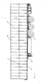
- in einer schematischen Seitenansicht ein Anhängerfahrzeug mit einem Ausführungsbeispiel eines Aufbaus nach der Erfindung; und
- Fig. 2
- einen Querschnitt gemäß der Schnittlinie F-F in
Fig. 1 durch eine Seitenwandung des Aufbaus. - In der Zeichnung sind nur die zum unmittelbaren Verständnis der Erfindung notwendigen Elemente eines Ausführungsbeispiels eines Aufbaus für ein Transportfahrzeug gezeigt.
- Allgemein mit 1 ist ein Anhängefahrzeug in
Fig. 1 veranschaulicht, das auf einem Chassis 2, das über Achsen und Räder 3 abgestützt ist, einen allgemein mit 4 bezifferten Aufbau trägt. Dieser Aufbau hat allgemein mit 5 bezifferte Seitenwände und einem allgemein mit 6 skizzierten Aufbauinnenraum zugewandte innere Deckschichten 7 und eine äußere Deckschicht 8. Zudem sind noch Bodenelemente 9 sowie Deckenelemente 10 vorgesehen. - Die Seitenwandung umfaßt die bereits erwähnte innere Deckschicht 7 und die äußere Deckschicht 8, die beispielsweise aus einem GFK-Material aber auch aus Stahlblech bestehen können. Als innere Auskleidung hat diese einen speziellen Strukturaufbau. Diese Struktur umfaßt zunächst eine Kleberschicht 11, mit der Vakuumisolationspaneele 12 mit der inneren Deckschicht 7 vollflächig zu verkleben sind. Mit dieser Kleberschicht 11 lassen sich auch Unebenheiten ausgleichen. Diese Kleberschicht hat ca. eine Dicke von jeweils 2 mm und sichert das jeweilige Vakuumisolationspaneel 12 vollflächig und damit unverrückbar an der inneren Deckschicht 7, wobei die Kleberschicht 11 jeweils eine Schutzschicht darstellt. Die aneinander gereihten Vakuumisolationspaneele 12 haben jeweils geradlinige Stirnkanten, wobei die aufeinanderzu gerichteten Stirnkanten von zwei benachbarten Paneelen wiederum über eine Stützträgerstruktur aneinander gehalten sind. Diese Stützträgerstruktur 13 umfaßt ihrerseits Stützträgerelemente 14 in Gestalt von Schaumblockträgerschichten, die wiederum mit den Stirnkanten über jeweils eine Kleberschicht 15 mit den Stirnkanten der Vakuumisolationspaneele verbunden sind. Somit sind die Vakuumisolationspaneele auch an ihren Stirnkanten sicher in die Kleberschicht eingebettet und durch die Stützträgerelemente als Stützkorsett sicher und geschützt Bestandteil der inneren Auskleidung zwischen den Deckschichten 7 und 8.
- Zur äußeren Deckschicht hin ausgerichtet sind die Vakuumisolationspaneele 12 wiederum mit einer Kleberschicht 16 versehen, bevorzugterweise wieder mit einer Schichtdicke von 2 mm. An diese Kleberschicht schließt sich eine Schicht 17 aus Blockschaum oder aus vor Ort zu schäumenden Kunststoffmaterial an, welches dann ebenfalls zu einer Schicht 17 führt. In dem Ausführungsbeispiel mit verwendetem Blockschaummaterial 17 ist zwischen der äußeren Deckschicht 8 und dem Blockschaum 17 wiederum eine Kleberschicht 18 vorgesehen, die den Blockschaum 17 unverrückbar und sicher an der äußeren Deckschicht 8 festhält. Insgesamt ist damit ein Aufbau zur Verfügung gestellt mit weit verbesserten Wärmedämmeigenschaften und den zuvor beschriebenen Vorteilen.
Claims (11)
- Aufbau (4) für Transportfahrzeuge, beispielsweise Kofferaufbau für Kühlfahrzeuge, mit einem von Seitenwandungen (5) sowie Decken (10)- und Bodenelementen (9) umgrenzten Aufbauinnenraum (6), wobei die Wandungen (5) und/oder Decken- (10) und Bodenelemente (9) mit einer inneren (7) und äußeren Deckschicht (8) sowie einer zwischen den Deckschichten (7, 8) gelegenen Auskleidung versehen sind, wobei zwischen der inneren (7) und der äußeren Deckschicht (8) eine Struktur aus aneinander gereihten Vakuumisolationspaneelen (12), Kleberschichten (11, 15, 16,18) und Schaumschichten (17) vorgesehen ist, dadurch gekennzeichnet, daß die Vakuumisolationspaneele (12) über eine Kleberschicht (11) mit der inneren Deckschicht (7) verbunden sind und zwischen den Vakuumisolationspaneelen (12) und der äußeren Deckschicht (8) ein Kunststoffschaum (17) sowie zwischen Vakuumisolationspaneelen (12) ein Stützkorsett aus Schaumträgerelementen (14) vorgesehen ist, wobei die Schaumträgerelemente (14) für das Stützkorsett durch Schaumplattenelemente gebildet sind, die mit einander zugewandten Stirnkanten der Vakuumisolationspaneele (12) verklebt sind.
- Aufbau nach Anspruch 1, dadurch gekennzeichnet, daß zwischen den Vakuumisolationspaneelen (12) und der äußeren Deckschicht (8) ein Blockschaum (17) vorgesehen ist.
- Aufbau nach Anspruch 1, dadurch gekennzeichnet, daß zwischen der äußeren Deckschicht (8) und den Vakuumisolationspaneelen (12) ein geschäumter Schaum vorgesehen ist.
- Aufbau nach einem der Ansprüche 1 bis 3, dadurch gekennzeichnet, daß zwischen der inneren Deckschicht (7) und den Vakuumisolationspaneelen (12) eine Kleberschicht von ca. 2 mm Dicke vorgesehen ist.
- Aufbau nach einem der Ansprüche 2 bis 4, dadurch gekennzeichnet, daß zwischen den Vakuumisolationspaneelen (12) und dem Blockschaum (17) eine weitere Kleberschicht (16) vorgesehen ist.
- Fahrzeugaufbau nach Anspruch 5, dadurch gekennzeichnet, daß die weitere Kleberschicht (16) eine Dicke von ca. 2 mm aufweist.
- Aufbau nach Anspruch 6, dadurch gekennzeichnet, daß die Schichtdicke der Kleberschicht (15) zwischen dem Schaumträgerlement und den Stirnkanten der Vakuumisolationspaneelen (12) ca. 2 mm ist.
- Fahrzeugaufbau nach einem der Ansprüche 1 bis 6, dadurch gekennzeichnet, daß die innere Deckschicht (7) aus einem GFK-Material oder Stahl besteht.
- Aufbau nach einem der Ansprüche 3 bis 8, dadurch gekennzeichnet, daß der geschäumte Schaum ein PUR-Schaummaterial ist.
- Aufbau nach einem der Ansprüche 1 bis 9, dadurch gekennzeichnet, daß der geschäumte Schaum ein unter Druck aushärtbares Reaktionsgemisch ist.
- Aufbau nach einem der Ansprüche 1 bis 10, dadurch gekennzeichnet, daß die Vakuumisolationspaneele (12) ein plattenförmiges, druckstabiles Kernmaterial aus einem verpreßten Pulver, einer Glasfaser oder einem offenporigen Kunststoffschaummaterial umfassen, das durch eine Folie gasdicht vakuumisoliert eingeschlossen ist.
Priority Applications (1)
| Application Number | Priority Date | Filing Date | Title |
|---|---|---|---|
| PL06021460T PL1785337T3 (pl) | 2005-11-14 | 2006-10-13 | Nadwozie do pojazdów transportowych |
Applications Claiming Priority (1)
| Application Number | Priority Date | Filing Date | Title |
|---|---|---|---|
| DE102005054538A DE102005054538A1 (de) | 2005-11-14 | 2005-11-14 | Aufbau für Transportfahrzeuge |
Publications (3)
| Publication Number | Publication Date |
|---|---|
| EP1785337A2 EP1785337A2 (de) | 2007-05-16 |
| EP1785337A3 EP1785337A3 (de) | 2008-07-23 |
| EP1785337B1 true EP1785337B1 (de) | 2010-01-06 |
Family
ID=37709630
Family Applications (1)
| Application Number | Title | Priority Date | Filing Date |
|---|---|---|---|
| EP06021460A Active EP1785337B1 (de) | 2005-11-14 | 2006-10-13 | Aufbau für Transportfahrzeuge |
Country Status (6)
| Country | Link |
|---|---|
| EP (1) | EP1785337B1 (de) |
| AT (1) | ATE454306T1 (de) |
| DE (2) | DE102005054538A1 (de) |
| DK (1) | DK1785337T3 (de) |
| ES (1) | ES2338912T3 (de) |
| PL (1) | PL1785337T3 (de) |
Families Citing this family (11)
| Publication number | Priority date | Publication date | Assignee | Title |
|---|---|---|---|---|
| AT505397B1 (de) * | 2007-07-19 | 2009-01-15 | Josef Mikl | Behälter zur aufnahme eines fluids |
| AT505660B1 (de) | 2007-07-19 | 2009-03-15 | Josef Mikl | Behälter zur aufnahme eines fluids |
| EP2363337B1 (de) | 2010-03-02 | 2015-05-06 | Ria Kaiser | Aufbau für ein Transportfahrzeug und Kühltransportfahrzeug mit einem solchen Aufbau |
| FR2963291B1 (fr) | 2010-07-27 | 2012-08-31 | Jean Chereau Sas | Module de carrosserie pour vehicule frigorifique comprenant un panneau d'isolation sous vide, et procede de fabrication associe. |
| DE102011016792A1 (de) * | 2011-04-12 | 2012-10-18 | GM Global Technology Operations LLC (n. d. Gesetzen des Staates Delaware) | Kraftfahrzeug mit einem Gasisolationspaneel |
| DE102012100490A1 (de) | 2012-01-23 | 2013-07-25 | Götz von Waldeyer-Hartz | Thermowand und Verfahren zu ihrer Herstellung |
| FR2991250B1 (fr) | 2012-06-05 | 2014-06-13 | Jean Chereau Sas | Module de carrosserie pour vehicule frigorifique comprenant un panneau d'isolation sous vide, et procede de fabrication associe. |
| CN105064549A (zh) * | 2015-08-14 | 2015-11-18 | 广西南宁环球汇狮新型建材有限公司 | 一种复合抗裂隔墙结构 |
| PL234517B1 (pl) * | 2018-01-09 | 2020-03-31 | Tomasz I Danuta Mrukowie P P U H Plandex Spolka Jawna | Zabudowa izotermiczna lub chłodnicza do specjalistycznych samochodów dostawczych i/lub ciężarowych |
| DE102018129606B4 (de) * | 2018-11-23 | 2020-08-06 | Kögel Trailer GmbH | Isolierpaneel, Komponente eines Fahrzeugaufbaus, Fahrzeugaufbau, Fahrzeug und Herstellungsverfahren |
| FR3100218B1 (fr) * | 2019-09-02 | 2026-04-24 | Jean Chereau Sas | Module de carrosserie pour véhicule frigorifique comprenant un panneau d’isolation sous vide, et procédé de fabrication associé |
Family Cites Families (5)
| Publication number | Priority date | Publication date | Assignee | Title |
|---|---|---|---|---|
| GB2241516A (en) * | 1990-02-17 | 1991-09-04 | Truck Panels Limited | Insulated panels and assemblies |
| ATE374686T1 (de) | 1999-04-12 | 2007-10-15 | Isuzu Motors Ltd | Wärmedämmendes mauerelement und verfahren zu dessen herstellung |
| WO2004001149A2 (de) * | 2002-06-24 | 2003-12-31 | Sager Ag | Vakuum-isolations-paneel, verfahren zur wärmedämmung von objekten sowie hilfsmittel dafür |
| WO2004071885A2 (en) | 2003-02-13 | 2004-08-26 | Martin Marietta Materials, Inc. | Insulated cargo containers |
| US7025408B2 (en) * | 2003-08-20 | 2006-04-11 | Great Dane Limited Partnership | Liner panel having barrier layer |
-
2005
- 2005-11-14 DE DE102005054538A patent/DE102005054538A1/de not_active Withdrawn
-
2006
- 2006-10-13 AT AT06021460T patent/ATE454306T1/de active
- 2006-10-13 ES ES06021460T patent/ES2338912T3/es active Active
- 2006-10-13 DK DK06021460.8T patent/DK1785337T3/da active
- 2006-10-13 PL PL06021460T patent/PL1785337T3/pl unknown
- 2006-10-13 EP EP06021460A patent/EP1785337B1/de active Active
- 2006-10-13 DE DE502006005828T patent/DE502006005828D1/de active Active
Also Published As
| Publication number | Publication date |
|---|---|
| DE102005054538A1 (de) | 2007-05-16 |
| PL1785337T3 (pl) | 2010-06-30 |
| DK1785337T3 (da) | 2010-05-10 |
| DE502006005828D1 (de) | 2010-02-25 |
| ATE454306T1 (de) | 2010-01-15 |
| EP1785337A2 (de) | 2007-05-16 |
| ES2338912T3 (es) | 2010-05-13 |
| EP1785337A3 (de) | 2008-07-23 |
Similar Documents
| Publication | Publication Date | Title |
|---|---|---|
| EP2771236B1 (de) | Bauelement | |
| EP0057909B1 (de) | Wohnwagenaufbau | |
| DE102007035228B4 (de) | Transportbehälter | |
| EP1785337A2 (de) | Aufbau für Transportfahrzeuge | |
| DE102011014302A1 (de) | Türelement für ein Kühl- und/oder Gefriergerät | |
| DE102012100490A1 (de) | Thermowand und Verfahren zu ihrer Herstellung | |
| EP2070806B9 (de) | Kofferaufbau mit einem Fahrzeugdach | |
| EP2363337B1 (de) | Aufbau für ein Transportfahrzeug und Kühltransportfahrzeug mit einem solchen Aufbau | |
| WO2008064662A1 (de) | Thermisches isolationssystem, insbesondere für lng-tankschiffe und verfahren zu dessen herstellung | |
| DE10215129A1 (de) | Bodenplatte für einen Kühlcontainer | |
| DE4210885A1 (de) | Heizungsvorrichtung | |
| DE102009002404B4 (de) | Biegeträger zur Bildung einer Bodenplatte eines Frachtraumbodens eines Flugzeuges, Bodenplatte mit einem solchen Biegeträger und Flugzeug mit einem solchen Biegeträger | |
| DE102013101584B4 (de) | Bodenelement für einen Nutzfahrzeugaufbau und Nutzfahrzeugaufbau oder Nutzfahrzeug mit einem derartigen Bodenelement | |
| KR20190033333A (ko) | 고성능 단열 구조재가 적용된 중대형 lpg 운반선 화물창 및 그 고성능 단열 구조재 | |
| DE102008022600A1 (de) | Verfahren zur Herstellung einer Geschossdeckendämmung und entsprechende Geschossdeckendämmung | |
| EP4396059B1 (de) | Brandgeschützte bodenstruktur eines wagenkastens in leichtbauweise | |
| EP2678490A1 (de) | Tragfähiges oder tragendes leichtbauelement | |
| EP4410704A1 (de) | Transportbehälter für den transport von temperaturempfindlichen produkten | |
| DE102023117869A1 (de) | Verbundwandelement zur herstellung einer thermisch isolierenden gebäudehülle oder eines thermisch isolierenden aufbaus für ein land- oder wasserfahrzeug | |
| KR20230023251A (ko) | 건축물의 단열구조재 | |
| DE19616369C1 (de) | Plattenbauelement und Dachkonstruktion,bestehend aus derartigen Plattenbauelementen | |
| DE1605041C (de) | Plattenbauteil für Wände od.dgl. von Kühlfahrzeugen, insbesondere Eisenbahn-Kühlwagen | |
| DE102011014206A1 (de) | Tragfähiges oder tragendes Leichtbauelement | |
| DE102009014855A1 (de) | Vakuum-Trocknungsvorrichtung | |
| DE1630117C3 (de) | Doppelwandiger Isolierbehälter, insbesondere Fahrzeugaufbau oder Container |
Legal Events
| Date | Code | Title | Description |
|---|---|---|---|
| PUAI | Public reference made under article 153(3) epc to a published international application that has entered the european phase |
Free format text: ORIGINAL CODE: 0009012 |
|
| AK | Designated contracting states |
Kind code of ref document: A2 Designated state(s): AT BE BG CH CY CZ DE DK EE ES FI FR GB GR HU IE IS IT LI LT LU LV MC NL PL PT RO SE SI SK TR |
|
| AX | Request for extension of the european patent |
Extension state: AL BA HR MK YU |
|
| RAP1 | Party data changed (applicant data changed or rights of an application transferred) |
Owner name: FAHRZEUGWERK BERNARD KRONE GMBH |
|
| PUAL | Search report despatched |
Free format text: ORIGINAL CODE: 0009013 |
|
| AK | Designated contracting states |
Kind code of ref document: A3 Designated state(s): AT BE BG CH CY CZ DE DK EE ES FI FR GB GR HU IE IS IT LI LT LU LV MC NL PL PT RO SE SI SK TR |
|
| AX | Request for extension of the european patent |
Extension state: AL BA HR MK RS |
|
| RIC1 | Information provided on ipc code assigned before grant |
Ipc: E04B 1/80 20060101ALI20080613BHEP Ipc: B62D 33/04 20060101AFI20070214BHEP Ipc: B60P 3/20 20060101ALI20080613BHEP |
|
| 17P | Request for examination filed |
Effective date: 20081002 |
|
| 17Q | First examination report despatched |
Effective date: 20081212 |
|
| AKX | Designation fees paid |
Designated state(s): AT BE BG CH CY CZ DE DK EE ES FI FR GB GR HU IE IS IT LI LT LU LV MC NL PL PT RO SE SI SK TR |
|
| GRAP | Despatch of communication of intention to grant a patent |
Free format text: ORIGINAL CODE: EPIDOSNIGR1 |
|
| GRAS | Grant fee paid |
Free format text: ORIGINAL CODE: EPIDOSNIGR3 |
|
| GRAA | (expected) grant |
Free format text: ORIGINAL CODE: 0009210 |
|
| AK | Designated contracting states |
Kind code of ref document: B1 Designated state(s): AT BE BG CH CY CZ DE DK EE ES FI FR GB GR HU IE IS IT LI LT LU LV MC NL PL PT RO SE SI SK TR |
|
| REG | Reference to a national code |
Ref country code: GB Ref legal event code: FG4D Free format text: NOT ENGLISH |
|
| REG | Reference to a national code |
Ref country code: CH Ref legal event code: EP |
|
| REG | Reference to a national code |
Ref country code: IE Ref legal event code: FG4D |
|
| REF | Corresponds to: |
Ref document number: 502006005828 Country of ref document: DE Date of ref document: 20100225 Kind code of ref document: P |
|
| REG | Reference to a national code |
Ref country code: SE Ref legal event code: TRGR |
|
| REG | Reference to a national code |
Ref country code: NL Ref legal event code: T3 |
|
| REG | Reference to a national code |
Ref country code: DK Ref legal event code: T3 |
|
| REG | Reference to a national code |
Ref country code: ES Ref legal event code: FG2A Ref document number: 2338912 Country of ref document: ES Kind code of ref document: T3 |
|
| PG25 | Lapsed in a contracting state [announced via postgrant information from national office to epo] |
Ref country code: SI Free format text: LAPSE BECAUSE OF FAILURE TO SUBMIT A TRANSLATION OF THE DESCRIPTION OR TO PAY THE FEE WITHIN THE PRESCRIBED TIME-LIMIT Effective date: 20100106 |
|
| LTIE | Lt: invalidation of european patent or patent extension |
Effective date: 20100106 |
|
| PG25 | Lapsed in a contracting state [announced via postgrant information from national office to epo] |
Ref country code: PT Free format text: LAPSE BECAUSE OF FAILURE TO SUBMIT A TRANSLATION OF THE DESCRIPTION OR TO PAY THE FEE WITHIN THE PRESCRIBED TIME-LIMIT Effective date: 20100506 Ref country code: LT Free format text: LAPSE BECAUSE OF FAILURE TO SUBMIT A TRANSLATION OF THE DESCRIPTION OR TO PAY THE FEE WITHIN THE PRESCRIBED TIME-LIMIT Effective date: 20100106 Ref country code: IS Free format text: LAPSE BECAUSE OF FAILURE TO SUBMIT A TRANSLATION OF THE DESCRIPTION OR TO PAY THE FEE WITHIN THE PRESCRIBED TIME-LIMIT Effective date: 20100506 |
|
| REG | Reference to a national code |
Ref country code: IE Ref legal event code: FD4D |
|
| PG25 | Lapsed in a contracting state [announced via postgrant information from national office to epo] |
Ref country code: LV Free format text: LAPSE BECAUSE OF FAILURE TO SUBMIT A TRANSLATION OF THE DESCRIPTION OR TO PAY THE FEE WITHIN THE PRESCRIBED TIME-LIMIT Effective date: 20100106 Ref country code: FI Free format text: LAPSE BECAUSE OF FAILURE TO SUBMIT A TRANSLATION OF THE DESCRIPTION OR TO PAY THE FEE WITHIN THE PRESCRIBED TIME-LIMIT Effective date: 20100106 |
|
| PG25 | Lapsed in a contracting state [announced via postgrant information from national office to epo] |
Ref country code: RO Free format text: LAPSE BECAUSE OF FAILURE TO SUBMIT A TRANSLATION OF THE DESCRIPTION OR TO PAY THE FEE WITHIN THE PRESCRIBED TIME-LIMIT Effective date: 20100106 Ref country code: IE Free format text: LAPSE BECAUSE OF FAILURE TO SUBMIT A TRANSLATION OF THE DESCRIPTION OR TO PAY THE FEE WITHIN THE PRESCRIBED TIME-LIMIT Effective date: 20100106 Ref country code: EE Free format text: LAPSE BECAUSE OF FAILURE TO SUBMIT A TRANSLATION OF THE DESCRIPTION OR TO PAY THE FEE WITHIN THE PRESCRIBED TIME-LIMIT Effective date: 20100106 Ref country code: CY Free format text: LAPSE BECAUSE OF FAILURE TO SUBMIT A TRANSLATION OF THE DESCRIPTION OR TO PAY THE FEE WITHIN THE PRESCRIBED TIME-LIMIT Effective date: 20100106 Ref country code: GR Free format text: LAPSE BECAUSE OF FAILURE TO SUBMIT A TRANSLATION OF THE DESCRIPTION OR TO PAY THE FEE WITHIN THE PRESCRIBED TIME-LIMIT Effective date: 20100407 |
|
| PLBE | No opposition filed within time limit |
Free format text: ORIGINAL CODE: 0009261 |
|
| STAA | Information on the status of an ep patent application or granted ep patent |
Free format text: STATUS: NO OPPOSITION FILED WITHIN TIME LIMIT |
|
| PG25 | Lapsed in a contracting state [announced via postgrant information from national office to epo] |
Ref country code: BG Free format text: LAPSE BECAUSE OF FAILURE TO SUBMIT A TRANSLATION OF THE DESCRIPTION OR TO PAY THE FEE WITHIN THE PRESCRIBED TIME-LIMIT Effective date: 20100406 Ref country code: SK Free format text: LAPSE BECAUSE OF FAILURE TO SUBMIT A TRANSLATION OF THE DESCRIPTION OR TO PAY THE FEE WITHIN THE PRESCRIBED TIME-LIMIT Effective date: 20100106 Ref country code: CZ Free format text: LAPSE BECAUSE OF FAILURE TO SUBMIT A TRANSLATION OF THE DESCRIPTION OR TO PAY THE FEE WITHIN THE PRESCRIBED TIME-LIMIT Effective date: 20100106 |
|
| 26N | No opposition filed |
Effective date: 20101007 |
|
| PG25 | Lapsed in a contracting state [announced via postgrant information from national office to epo] |
Ref country code: MC Free format text: LAPSE BECAUSE OF NON-PAYMENT OF DUE FEES Effective date: 20101031 |
|
| REG | Reference to a national code |
Ref country code: CH Ref legal event code: PL |
|
| PG25 | Lapsed in a contracting state [announced via postgrant information from national office to epo] |
Ref country code: CH Free format text: LAPSE BECAUSE OF NON-PAYMENT OF DUE FEES Effective date: 20101031 Ref country code: LI Free format text: LAPSE BECAUSE OF NON-PAYMENT OF DUE FEES Effective date: 20101031 |
|
| PG25 | Lapsed in a contracting state [announced via postgrant information from national office to epo] |
Ref country code: LU Free format text: LAPSE BECAUSE OF NON-PAYMENT OF DUE FEES Effective date: 20101013 Ref country code: HU Free format text: LAPSE BECAUSE OF FAILURE TO SUBMIT A TRANSLATION OF THE DESCRIPTION OR TO PAY THE FEE WITHIN THE PRESCRIBED TIME-LIMIT Effective date: 20100707 |
|
| REG | Reference to a national code |
Ref country code: FR Ref legal event code: PLFP Year of fee payment: 10 |
|
| REG | Reference to a national code |
Ref country code: FR Ref legal event code: PLFP Year of fee payment: 11 |
|
| REG | Reference to a national code |
Ref country code: FR Ref legal event code: PLFP Year of fee payment: 12 |
|
| REG | Reference to a national code |
Ref country code: FR Ref legal event code: PLFP Year of fee payment: 13 |
|
| P01 | Opt-out of the competence of the unified patent court (upc) registered |
Effective date: 20230518 |
|
| PGFP | Annual fee paid to national office [announced via postgrant information from national office to epo] |
Ref country code: NL Payment date: 20251023 Year of fee payment: 20 |
|
| PGFP | Annual fee paid to national office [announced via postgrant information from national office to epo] |
Ref country code: DE Payment date: 20251020 Year of fee payment: 20 |
|
| PGFP | Annual fee paid to national office [announced via postgrant information from national office to epo] |
Ref country code: GB Payment date: 20251024 Year of fee payment: 20 |
|
| PGFP | Annual fee paid to national office [announced via postgrant information from national office to epo] |
Ref country code: AT Payment date: 20251021 Year of fee payment: 20 |
|
| PGFP | Annual fee paid to national office [announced via postgrant information from national office to epo] |
Ref country code: DK Payment date: 20251023 Year of fee payment: 20 Ref country code: IT Payment date: 20251031 Year of fee payment: 20 |
|
| PGFP | Annual fee paid to national office [announced via postgrant information from national office to epo] |
Ref country code: FR Payment date: 20251029 Year of fee payment: 20 |
|
| PGFP | Annual fee paid to national office [announced via postgrant information from national office to epo] |
Ref country code: TR Payment date: 20251006 Year of fee payment: 20 Ref country code: BE Payment date: 20251022 Year of fee payment: 20 |
|
| PGFP | Annual fee paid to national office [announced via postgrant information from national office to epo] |
Ref country code: SE Payment date: 20251023 Year of fee payment: 20 |
|
| PGFP | Annual fee paid to national office [announced via postgrant information from national office to epo] |
Ref country code: PL Payment date: 20251002 Year of fee payment: 20 |
|
| PGFP | Annual fee paid to national office [announced via postgrant information from national office to epo] |
Ref country code: ES Payment date: 20251114 Year of fee payment: 20 |