EP1785341A1 - Structure de feu arrière - Google Patents
Structure de feu arrière Download PDFInfo
- Publication number
- EP1785341A1 EP1785341A1 EP06123101A EP06123101A EP1785341A1 EP 1785341 A1 EP1785341 A1 EP 1785341A1 EP 06123101 A EP06123101 A EP 06123101A EP 06123101 A EP06123101 A EP 06123101A EP 1785341 A1 EP1785341 A1 EP 1785341A1
- Authority
- EP
- European Patent Office
- Prior art keywords
- tail lamp
- bulb
- lens
- reflector portion
- tail
- Prior art date
- Legal status (The legal status is an assumption and is not a legal conclusion. Google has not performed a legal analysis and makes no representation as to the accuracy of the status listed.)
- Granted
Links
- 239000011347 resin Substances 0.000 claims description 8
- 229920005989 resin Polymers 0.000 claims description 8
- 238000005286 illumination Methods 0.000 description 7
- 238000010276 construction Methods 0.000 description 6
- 230000020169 heat generation Effects 0.000 description 4
- 238000000034 method Methods 0.000 description 3
- 239000003086 colorant Substances 0.000 description 2
- 238000004519 manufacturing process Methods 0.000 description 2
- 230000005540 biological transmission Effects 0.000 description 1
- 210000000078 claw Anatomy 0.000 description 1
- 239000000463 material Substances 0.000 description 1
Images


Classifications
-
- B—PERFORMING OPERATIONS; TRANSPORTING
- B60—VEHICLES IN GENERAL
- B60Q—ARRANGEMENT OF SIGNALLING OR LIGHTING DEVICES, THE MOUNTING OR SUPPORTING THEREOF OR CIRCUITS THEREFOR, FOR VEHICLES IN GENERAL
- B60Q1/00—Arrangement of optical signalling or lighting devices, the mounting or supporting thereof or circuits therefor
- B60Q1/26—Arrangement of optical signalling or lighting devices, the mounting or supporting thereof or circuits therefor the devices being primarily intended to indicate the vehicle, or parts thereof, or to give signals, to other traffic
- B60Q1/2607—Arrangement of optical signalling or lighting devices, the mounting or supporting thereof or circuits therefor the devices being primarily intended to indicate the vehicle, or parts thereof, or to give signals, to other traffic comprising at least two indicating lamps
-
- B—PERFORMING OPERATIONS; TRANSPORTING
- B60—VEHICLES IN GENERAL
- B60Q—ARRANGEMENT OF SIGNALLING OR LIGHTING DEVICES, THE MOUNTING OR SUPPORTING THEREOF OR CIRCUITS THEREFOR, FOR VEHICLES IN GENERAL
- B60Q1/00—Arrangement of optical signalling or lighting devices, the mounting or supporting thereof or circuits therefor
- B60Q1/26—Arrangement of optical signalling or lighting devices, the mounting or supporting thereof or circuits therefor the devices being primarily intended to indicate the vehicle, or parts thereof, or to give signals, to other traffic
- B60Q1/56—Arrangement of optical signalling or lighting devices, the mounting or supporting thereof or circuits therefor the devices being primarily intended to indicate the vehicle, or parts thereof, or to give signals, to other traffic for illuminating registrations or the like, e.g. for licence plates
-
- B—PERFORMING OPERATIONS; TRANSPORTING
- B62—LAND VEHICLES FOR TRAVELLING OTHERWISE THAN ON RAILS
- B62J—CYCLE SADDLES OR SEATS; AUXILIARY DEVICES OR ACCESSORIES SPECIALLY ADAPTED TO CYCLES AND NOT OTHERWISE PROVIDED FOR, e.g. ARTICLE CARRIERS OR CYCLE PROTECTORS
- B62J6/00—Arrangement of optical signalling or lighting devices on cycles; Mounting or supporting thereof; Circuits therefor
- B62J6/04—Rear lights
- B62J6/045—Rear lights indicating braking
Definitions
- the present invention relates to a tail lamp structure, and more specifically to a tail lamp structure that can prevent an increase in the size of a tail lamp unit and enhance the freedom of layout.
- a tail lamp device using a double-filament bulb in which filaments of different wattages for a tail lamp and for a stop lamp are received within a single electric bulb. Further, the construction of a tail lamp device in which the tail lamp and the stop lamp are made of separate bulbs and respectively received in separate cases (housings) is also known.
- Document JP-Y No. S59-1884 discloses the construction of a tail lamp device in which a bulb for a tail/stop lamp made of a double-filament bulb is arranged at substantially the central portion within a single case, a shielding plate is formed on each of the left and right of the bulb, a bulb for a winker (direction indicator lamp) is arranged on the outer side in the vehicle width direction of the shielding plate, and the portions above the respective bulbs are covered by a lens integrally formed of a red lens and an orange lens.
- Document JP-Y No. H02-117279 discloses the construction of a tail lamp device in which the case of a stop lamp is arranged above the case of a tail lamp in rear of a seat on which the occupant sits.
- JP-Y No. S59-1884 involves a problem in that since the amount of heat generation by a double-filament bulb is large, the case formed of resin or the like must have a size sufficient to make it insusceptible to the influence of the amount of heat generation, leading to an increase in the size of the tail lamp device.
- a tail lamp structure for a motorcycle including a housing, a lens, and a bulb that are integrally formed, wherein: the bulb includes a tail lamp bulb and a stop lamp bulb; the tail lamp bulb and the stop lamp bulb are arranged on the same horizontal plane or substantially the same horizontal plane within the same section; the tail lamp bulb and the stop lamp bulb are arranged at the bottom of a reflector portion formed by the housing; and the reflector portion is covered by the lens.
- the tail lamp bulb is arranged at substantially the center in a vehicle width direction, and the stop lamp bulb is arranged on each of the left and right of the tail lamp bulb.
- a shielding plate is provided at each of left and right side edges of the reflector portion where the tail lamp bulb and the stop lamp bulb are arranged, and a reflector portion where a winker bulb is arranged is formed on an outer side in the vehicle width direction of the shielding plate.
- the lens is split between a portion that covers the reflector portion where the tail lamp bulb and the stop lamp bulb are arranged, and a portion that covers the reflector portion where the winker bulb is arranged.
- the portion of the lens which covers the reflector portion where the tail lamp bulb and the stop lamp bulb are arranged is formed of transparent red or substantially transparent red resin
- the portion of the lens which covers the reflector portion where the winker bulb is arranged is formed of transparent orange or substantially transparent orange resin.
- a transparent white or substantially transparent white license plate lamp lens is arranged below the tail lamp lens so as to be sandwiched between the housing and the lens, and a plate-like projection is provided below the stop lamp bulb.
- the tail lamp bulb and the stop lamp bulb are provided separately, the amount of heat generation upon illumination can be reduced as compared with double-filament bulbs, and the size of the housing in the height direction can be reduced. Further, since the tail lamp and the stop lamp are received within the same housing, as compared with the case where these lamps are received in separate housings, the number of parts is reduced, and the freedom of layout can be enhanced. Furthermore, the tail lamp bulb and the stop lamp bulb are arranged on the horizontal plane or substantially horizontal plane, the dimension of the housing in the height direction, in particular, can be reduced.
- the stop lamp bulb is arranged on each of the left and right of the tail lamp bulb at the center, the irradiation range of the stop lamp is broadened in the lateral direction while reducing the height of the housing, thereby making it possible to ensure high visibility upon illumination.
- the third aspect of the present invention it is possible to obtain a tail lamp unit having the tail/stop lamp and the winker lamp integrally formed therein.
- the segmented manufacture makes it possible to simplify the manufacturing process. Further, it becomes easy to form the respective lens using materials of different colors. Furthermore, by reducing the height of the housing of the tail lamp and the stop lamp, the height of the winker lens surface can also be reduced, whereby the height of the lens surface of the tail lamp unit is reduced as a whole to impart a sharp impression for enhanced exterior appearance.
- the tail/stop lamp that illuminates in red is arranged at substantially the center in the vehicle width direction, and the winker lamp that illuminates in orange is integrally arranged on each of the left and right of the tail/stop lamp.
- the irradiation light to the license plate does not change due to the illumination of the stop lamp upon braking and can irradiate the license plate.
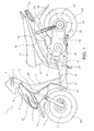
- FIG. 1 is a side view of an embodiment of a motorcycle to which the present invention is applied.
- a motorcycle 1 is a scooter type motorcycle equipped with a unit swing type power unit with a built-in continuously variable transmission.
- a pair of left and right front forks 6 are pivotally mounted on a head pipe 3 fixedly coupled to a main frame 2 as a body frame.
- a front wheel WF is rotatably pivoted on an axle 7 at the lower end of the front forks 6.
- the front forks 6 can be steered by means of a handlebar 4 that projects laterally in the vehicle width direction from a handlebar cover 5.
- a front fender 10 covering the portion above the front wheel WF is steered integrally with the front forks 6.
- a left-right two-lamp headlight unit 30, and a winker unit 70 consisting of a left-right pair is mounted to a front cover 9 that is a body cover arranged above the front fender 10.
- a split-type center cover 8 is connected to an upper portion of the front cover 9 so as to form a continuous exterior surface with the front cover 9.
- a cover panel 26 for covering the main frame 2 is arranged on the vehicle rear side of the front cover 9. At its lower portion, the cover panel 26 is joined to a step floor 15 on which the feet of the occupant are placed.
- a front lower cover 13 connected to a lower portion of the front cover 9 is joined to an under cover 14 located below the step floor 15.
- a side stand 27 is installed at a lower rear portion of the main frame 2.
- a seat frame 16 for supporting a seat 11, on which the occupant sits, a body cover 12, and the like is also coupled to the lower rear portion of the main frame 2.
- a power unit 22 including an engine 17, a carburetor 18, and an air cleaner box 19 is pivotally mounted on the main frame 2 in the rear of the body.
- the power unit 22 is suspended by means of a rear cushion 23, which is attached to the seat frame 16, so as to be rockable about the one end side.
- a rear wheel WR as a drive wheel is journalled to the other end side of the power unit 22 so as to be rotatable about an axle 65.
- an exhaust pipe 20 whose one end is connected to an exhaust port (not shown) provided in the cylinder head of the engine 17 is coupled to a muffler 21 in the rear of the vehicle.
- a main stand 28 for holding the motorcycle 1 upright when the occupant gets off the vehicle.
- a tail lamp unit 40 served as a tail lamp structure, in which a tail lamp and a stop lamp, and left and right winker lamps are integrally formed, is arranged at the end of the body cover 12 in the rear of the vehicle.
- a rear fender 25 that covers the rear wheel WR is mounted below the tail lamp unit 40.
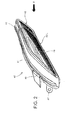
- Fig. 2 is a side view of the tail lamp unit 40 as a tail lamp structure according to an embodiment of the present invention.
- a housing 41 of the tail lamp unit 40 is engaged with the body cover 12 by means of engaging claws 44, 45, and is fastened onto the seat frame 16 or the like at fastening portions 46, 47 with bolts or the like.
- the housing 41 is formed integrally from resin or the like, with a tail/stop lamp lens 42 and a left tail lamp unit 43L being provided in the surface thereof.
- the tail lamp unit 40 integrally constituting the left and right winker units is shaped so that the housing 41 as a whole is raised upward toward the rear end thereof, thereby making it possible to impart the rear portion of the motorcycle 1 with a sharp exterior appearance.
- Fig. 3 is a view as seen in the direction A of Fig. 2, and is a front view of the tail lamp unit 40.
- Reference numerals that are the same as those described above denote portions that are the same as or equivalent to those described above.
- the left winker lens 43L and a right winker lens 43R are arranged on the left and right of the tail/stop lamp lens 42 at the central portion of the housing 41. These three lenses form an integral surface and a substantially crescent-shaped continuous contour, thereby imparting the tail lamp unit 40 with a sharp exterior appearance.
- Fig. 4 is a front view of the tail lamp unit 40 with the three lens removed. Reference numerals that are the same as those described above denote portions that are the same as or equivalent to those described above.
- a central reflector portion 60, left and right shielding plates 61, a left reflector portion 62L, and a right reflector portion 62R are integrally formed in the housing 41.
- a tail lamp bulb 50 is mounted to the center of the central reflector portion 60, with stop lamp bulbs 51L, 51R being mounted on the left and right of the tail lamp bulb 50.
- left and right winker bulbs 52L, 52R that are lit and flashed as direction indicator lamps or hazard lamps are respectively mounted to the left reflector portion 62L and the right reflector portion 62R, which are formed with the shielding plates 61 therebetween.
- the tail lamp bulb 50 and the stop lamp bulbs 51L, 51R are both single-filament lamps, the amount of heat generation can be suppressed as compared with double-filament lamps. Accordingly, in the case of the horizontal arrangement as described above, in particular, the height dimension of the portion of the housing 41 where the central reflector portion 60 is formed can be reduced, whereby the freedom of design can be enhanced. Further, since the tail lamp bulb 50 and the stop lamp bulbs 51L, 51R are received within the same housing, as compared with the case where separate housings are provided, the freedom of layout can also be enhanced.
- stop lamp bulbs 51L, 51R are arranged on the left and right of the tail lamp bulb 50, the irradiation range upon illumination of the stop lamps becomes broader in the lateral direction, thereby making it possible to enhance the visibility of the stop lamps. It should be understood as a matter of course that while in this embodiment the stop lamp bulbs 51L, 51R are arranged slightly below the tail lamp bulb 50, in accordance with the design of the tail lamp unit 40, the three bulbs may be arranged on the same horizontal plane, or the stop lamp bulbs 51L, 51R may be arranged slightly above the tail lamp bulb 50.
- Fig. 5 is a sectional view taken along the line B-B of Fig. 4.
- Reference numerals that are the same as those described above denote portions that are the same as or equivalent to those described above.
- an uneven portion is provided at the bottom of the central reflector portion 60, and the tail lamp bulb 50 with a bulb wattage lower than that of the stop lamp bulbs 51L, 51R is formed so as to slightly project toward the rear side of the vehicle (downward in the drawing).
- a socket 80 of the tail lamp bulb 50 coupled to a wire cord 81 is fixed to an opening provided in the central reflector portion 60 by means of a screw-fit engagement structure.
- the tail/stop lamp bulb 42, and the left winker lens 43L and the right winker lens 43R are brought into fitting engagement with each other so as to form a surface whose entire lens surface is smooth, near the rear end of the shielding plates 61 extended toward the rear of the vehicle from the central reflector portion 60.
- the three lenses are each fitted and fixed onto the housing 41.
- the tail/stop lamp lens 42 is formed of transparent red or substantially transparent red resin or the like, and the left winker lens 43L and the right winker lens 43R are formed of transparent orange and substantially transparent orange resin or the like so that the respective lenses are illuminated in red or orange; however, it is also possible to color the surfaces of the bulbs in respective colors and make the respective lenses transparent white or substantially transparent white.
- the three lenses may be formed integrally, and joining of the lenses to the housing 41 may be effected by fastening with a bolt or the like.
- Fig. 6 is a sectional view taken along the line C-C of Fig. 4. Reference numerals that are the same as those described above denote portions that are the same as or equivalent to those described above.
- a transparent white or substantially transparent white license plate lamp lens 63 is arranged below the tail lamp bulb 50, which illuminates during illumination or the like of the headlight unit 30, so as to be sandwiched between the housing 41 and the tail/stop lamp lens 42.
- the license plate lamp lens 63 serves to illuminate a license plate (not shown) installed in the rear fender 25 (see Fig. 1) below the tail lamp unit 40 by transmitting white light through a portion below the tail lamp bulb 50.
- the tail/stop lamp lens 42 is formed so that its lens surface is largely tilted toward the rear side of the vehicle; by forming an elongate and sharp contour at the rear end of the vehicle in combination with the shape of the body cover 12, it is possible to give the motorcycle 1 a tight, well-defined impression.
- Fig. 7 is a sectional view taken along the line D-D of Fig. 4. Reference numerals that are the same as those described above denote portions that are the same as or equivalent to those described above.
- the cross-sectional area of the license plate lamp lens 63 is made small below the stop lamp 51R, and the central reflector portion 60 is provided with a plate-like projection 60a.
- the above-described construction is to prevent the irradiation light to the license plate from changing due to illumination of the stop lamp upon braking; the same construction applies to the left-hand side in the vehicle width direction where the stop lamp bulb 51L is arranged.
- the tail lamp and the stop lamps are made of separate single-filament lamps and received within the same housing, thereby making it possible to reduce the height of the lamp member and therefore miniaturization of the tail lamp unit. Further, since the tail lamp and the stop lamps are received within the same housing, the freedom of layout can be enhanced as compared with the case where they are received in separate housings (cases). Furthermore, since one stop lamp bulb is arranged on each of the left and right of the tail lamp bulb at the center, the irradiation range can be broadened in the lateral direction while reducing the height of the lamp member, thereby ensuring high visibility upon illumination of the stop lamps.
- the configurations of the housing, reflector portion, lenses, and the like, the sizes, kinds, arrangement, and the like of the respective lamp bulbs are not limited to those of the above-described embodiments but may be modified in various ways, and are applicable to other than a tail lamp unit as well. Further, the lamps are not limited to a tail lamp or a stop lamp, either.
Landscapes
- Engineering & Computer Science (AREA)
- Mechanical Engineering (AREA)
- Lighting Device Outwards From Vehicle And Optical Signal (AREA)
- Non-Portable Lighting Devices Or Systems Thereof (AREA)
Applications Claiming Priority (1)
| Application Number | Priority Date | Filing Date | Title |
|---|---|---|---|
| JP2005326021A JP4535331B2 (ja) | 2005-11-10 | 2005-11-10 | テールランプ構造体 |
Publications (2)
| Publication Number | Publication Date |
|---|---|
| EP1785341A1 true EP1785341A1 (fr) | 2007-05-16 |
| EP1785341B1 EP1785341B1 (fr) | 2008-08-13 |
Family
ID=37762637
Family Applications (1)
| Application Number | Title | Priority Date | Filing Date |
|---|---|---|---|
| EP06123101A Not-in-force EP1785341B1 (fr) | 2005-11-10 | 2006-10-27 | Structure de feu arrière |
Country Status (5)
| Country | Link |
|---|---|
| EP (1) | EP1785341B1 (fr) |
| JP (1) | JP4535331B2 (fr) |
| CN (1) | CN1963291B (fr) |
| BR (1) | BRPI0604514B1 (fr) |
| ES (1) | ES2313568T3 (fr) |
Cited By (7)
| Publication number | Priority date | Publication date | Assignee | Title |
|---|---|---|---|---|
| EP2236398A1 (fr) * | 2009-03-31 | 2010-10-06 | Honda Motor Co., Ltd. | Véhicule à monture de selle |
| EP2301802A1 (fr) * | 2009-09-16 | 2011-03-30 | Honda Motor Co., Ltd. | Structure de dispositif d'éclairage arrière pour motocyclette |
| EP2447139A4 (fr) * | 2009-08-31 | 2012-05-30 | Honda Motor Co Ltd | Motocycle |
| CN102679211A (zh) * | 2012-04-05 | 2012-09-19 | 苏州佳世达电通有限公司 | 灯具 |
| EP2192031A4 (fr) * | 2007-12-28 | 2012-09-26 | Honda Motor Co Ltd | Véhicule à moteur à deux roues |
| EP2394891A3 (fr) * | 2010-06-11 | 2013-07-17 | Yamaha Hatsudoki Kabushiki Kaisha | Unité de lampe arrière pour motocyclette |
| CN104512498A (zh) * | 2013-09-27 | 2015-04-15 | 本田技研工业株式会社 | 车辆的尾灯结构 |
Families Citing this family (9)
| Publication number | Priority date | Publication date | Assignee | Title |
|---|---|---|---|---|
| JP5022168B2 (ja) * | 2007-10-10 | 2012-09-12 | 本田技研工業株式会社 | 自動二輪車のテールライトユニット |
| JP2013112309A (ja) * | 2011-11-30 | 2013-06-10 | Yamaha Motor Co Ltd | 鞍乗型車両 |
| JP2014083857A (ja) * | 2012-10-19 | 2014-05-12 | Yamaha Motor Co Ltd | 方向指示灯およびそれを備える鞍乗型車両 |
| FR3016684B1 (fr) * | 2014-01-21 | 2019-05-10 | Psa Automobiles Sa. | Dispositif d'eclairage de vehicule, en particulier d'eclairage diurne, et vehicule ainsi equipe |
| JP6532674B2 (ja) * | 2014-12-26 | 2019-06-19 | 川崎重工業株式会社 | 鞍乗型車両 |
| CN107776748B (zh) * | 2016-08-30 | 2019-11-19 | 本田技研工业株式会社 | 鞍乘型车辆的后组合灯 |
| JP6992160B2 (ja) * | 2018-03-29 | 2022-02-15 | 本田技研工業株式会社 | 鞍乗型車両 |
| JP6937793B2 (ja) * | 2019-04-05 | 2021-09-22 | 本田技研工業株式会社 | 鞍乗り型車両の後部構造 |
| JP2025091859A (ja) * | 2023-12-08 | 2025-06-19 | ヤマハ発動機株式会社 | 鞍乗型車両 |
Citations (8)
| Publication number | Priority date | Publication date | Assignee | Title |
|---|---|---|---|---|
| JPS591884A (ja) | 1982-06-25 | 1984-01-07 | Matsushita Electric Ind Co Ltd | ガス遮断装置 |
| JPH02117279A (ja) | 1988-10-27 | 1990-05-01 | Matsushita Electric Ind Co Ltd | 映像信号処理装置 |
| FR2687116A1 (fr) * | 1992-02-07 | 1993-08-13 | Honda Motor Co Ltd | Feu de stop pour motocycles, monte en position haute. |
| JPH06156341A (ja) * | 1992-11-27 | 1994-06-03 | Honda Motor Co Ltd | 自動二輪車のランプ配置構造 |
| JP2002193160A (ja) * | 2000-12-27 | 2002-07-10 | Yamaha Motor Co Ltd | 車両用テールライトとカバーリヤフェンダとの取付構造 |
| WO2003035457A1 (fr) * | 2001-10-24 | 2003-05-01 | Honda Giken Kogyo Kabushiki Kaisha | Eclairage arriere combine de motocyclette |
| EP1422132A2 (fr) * | 2002-11-22 | 2004-05-26 | HONDA MOTOR CO., Ltd. | Feu arrière pour un véhicule |
| WO2005002955A1 (fr) * | 2003-07-04 | 2005-01-13 | Yamaha Hatsudoki Kabushiki Kaisha | Motocycle |
Family Cites Families (2)
| Publication number | Priority date | Publication date | Assignee | Title |
|---|---|---|---|---|
| JPS62135304U (fr) * | 1986-02-19 | 1987-08-26 | ||
| JP4108290B2 (ja) * | 2001-03-28 | 2008-06-25 | 本田技研工業株式会社 | 車両の後部構造 |
-
2005
- 2005-11-10 JP JP2005326021A patent/JP4535331B2/ja not_active Expired - Fee Related
-
2006
- 2006-10-27 ES ES06123101T patent/ES2313568T3/es active Active
- 2006-10-27 EP EP06123101A patent/EP1785341B1/fr not_active Not-in-force
- 2006-10-31 CN CN2006101429503A patent/CN1963291B/zh not_active Expired - Fee Related
- 2006-11-01 BR BRPI0604514A patent/BRPI0604514B1/pt not_active IP Right Cessation
Patent Citations (8)
| Publication number | Priority date | Publication date | Assignee | Title |
|---|---|---|---|---|
| JPS591884A (ja) | 1982-06-25 | 1984-01-07 | Matsushita Electric Ind Co Ltd | ガス遮断装置 |
| JPH02117279A (ja) | 1988-10-27 | 1990-05-01 | Matsushita Electric Ind Co Ltd | 映像信号処理装置 |
| FR2687116A1 (fr) * | 1992-02-07 | 1993-08-13 | Honda Motor Co Ltd | Feu de stop pour motocycles, monte en position haute. |
| JPH06156341A (ja) * | 1992-11-27 | 1994-06-03 | Honda Motor Co Ltd | 自動二輪車のランプ配置構造 |
| JP2002193160A (ja) * | 2000-12-27 | 2002-07-10 | Yamaha Motor Co Ltd | 車両用テールライトとカバーリヤフェンダとの取付構造 |
| WO2003035457A1 (fr) * | 2001-10-24 | 2003-05-01 | Honda Giken Kogyo Kabushiki Kaisha | Eclairage arriere combine de motocyclette |
| EP1422132A2 (fr) * | 2002-11-22 | 2004-05-26 | HONDA MOTOR CO., Ltd. | Feu arrière pour un véhicule |
| WO2005002955A1 (fr) * | 2003-07-04 | 2005-01-13 | Yamaha Hatsudoki Kabushiki Kaisha | Motocycle |
Cited By (11)
| Publication number | Priority date | Publication date | Assignee | Title |
|---|---|---|---|---|
| EP2192031A4 (fr) * | 2007-12-28 | 2012-09-26 | Honda Motor Co Ltd | Véhicule à moteur à deux roues |
| EP2236398A1 (fr) * | 2009-03-31 | 2010-10-06 | Honda Motor Co., Ltd. | Véhicule à monture de selle |
| EP2447139A4 (fr) * | 2009-08-31 | 2012-05-30 | Honda Motor Co Ltd | Motocycle |
| US8845154B2 (en) | 2009-08-31 | 2014-09-30 | Honda Motor Co., Ltd. | Motorcycle |
| EP2301802A1 (fr) * | 2009-09-16 | 2011-03-30 | Honda Motor Co., Ltd. | Structure de dispositif d'éclairage arrière pour motocyclette |
| US8342724B2 (en) | 2009-09-16 | 2013-01-01 | Honda Motor Co., Ltd. | Rear lighting device for a vehicle |
| EP2394891A3 (fr) * | 2010-06-11 | 2013-07-17 | Yamaha Hatsudoki Kabushiki Kaisha | Unité de lampe arrière pour motocyclette |
| CN102679211A (zh) * | 2012-04-05 | 2012-09-19 | 苏州佳世达电通有限公司 | 灯具 |
| CN102679211B (zh) * | 2012-04-05 | 2015-06-10 | 苏州佳世达电通有限公司 | 灯具 |
| CN104512498A (zh) * | 2013-09-27 | 2015-04-15 | 本田技研工业株式会社 | 车辆的尾灯结构 |
| CN104512498B (zh) * | 2013-09-27 | 2017-08-15 | 本田技研工业株式会社 | 车辆的尾灯结构 |
Also Published As
| Publication number | Publication date |
|---|---|
| BRPI0604514A (pt) | 2007-08-28 |
| EP1785341B1 (fr) | 2008-08-13 |
| ES2313568T3 (es) | 2009-03-01 |
| JP2007131152A (ja) | 2007-05-31 |
| JP4535331B2 (ja) | 2010-09-01 |
| CN1963291A (zh) | 2007-05-16 |
| BRPI0604514B1 (pt) | 2017-01-17 |
| CN1963291B (zh) | 2012-04-11 |
Similar Documents
| Publication | Publication Date | Title |
|---|---|---|
| EP1785341B1 (fr) | Structure de feu arrière | |
| JP6257736B2 (ja) | 自動二輪車用前照灯 | |
| US9593817B2 (en) | Headlight device of motorcycle | |
| KR101195731B1 (ko) | 자동이륜차의 포지션 라이트 및 등화 장치 | |
| CN100443358C (zh) | 摩托车 | |
| US8342724B2 (en) | Rear lighting device for a vehicle | |
| US20080205073A1 (en) | Structure of Tail Light for Motorcycle | |
| CN100570206C (zh) | 车辆的前照灯结构 | |
| JP6537779B2 (ja) | 車両用灯火器 | |
| CN102530138B (zh) | 机动二轮车的灯光装置 | |
| EP2192031A1 (fr) | Véhicule à moteur à deux roues | |
| CN101545603A (zh) | 车辆的前照灯结构 | |
| CN1331704C (zh) | 灯装置 | |
| TW201733840A (zh) | 傾斜式車輛 | |
| TW200424077A (en) | Combination lamp | |
| CN104743008B (zh) | 二轮摩托车的前部结构 | |
| CN104554557B (zh) | 跨坐型车辆 | |
| JP5912757B2 (ja) | 鞍乗型車両の灯火器支持構造 | |
| TWI438113B (zh) | Straddle type vehicle | |
| TWI581990B (zh) | Straddle type vehicle | |
| JP2002216509A (ja) | 車両用ヘッドライト装置 | |
| CN101294674A (zh) | 前照灯构造 | |
| EP1780104B1 (fr) | Structure pré-montée de clignotant | |
| TWI646007B (zh) | Straddle type vehicle | |
| TWI511899B (zh) | Straddle type vehicle |
Legal Events
| Date | Code | Title | Description |
|---|---|---|---|
| PUAI | Public reference made under article 153(3) epc to a published international application that has entered the european phase |
Free format text: ORIGINAL CODE: 0009012 |
|
| 17P | Request for examination filed |
Effective date: 20061027 |
|
| AK | Designated contracting states |
Kind code of ref document: A1 Designated state(s): AT BE BG CH CY CZ DE DK EE ES FI FR GB GR HU IE IS IT LI LT LU LV MC NL PL PT RO SE SI SK TR |
|
| AX | Request for extension of the european patent |
Extension state: AL BA HR MK YU |
|
| AKX | Designation fees paid |
Designated state(s): ES FR IT |
|
| GRAP | Despatch of communication of intention to grant a patent |
Free format text: ORIGINAL CODE: EPIDOSNIGR1 |
|
| REG | Reference to a national code |
Ref country code: DE Ref legal event code: 8566 |
|
| GRAS | Grant fee paid |
Free format text: ORIGINAL CODE: EPIDOSNIGR3 |
|
| GRAA | (expected) grant |
Free format text: ORIGINAL CODE: 0009210 |
|
| AK | Designated contracting states |
Kind code of ref document: B1 Designated state(s): ES FR IT |
|
| REG | Reference to a national code |
Ref country code: ES Ref legal event code: FG2A Ref document number: 2313568 Country of ref document: ES Kind code of ref document: T3 |
|
| PLBE | No opposition filed within time limit |
Free format text: ORIGINAL CODE: 0009261 |
|
| STAA | Information on the status of an ep patent application or granted ep patent |
Free format text: STATUS: NO OPPOSITION FILED WITHIN TIME LIMIT |
|
| 26N | No opposition filed |
Effective date: 20090514 |
|
| REG | Reference to a national code |
Ref country code: FR Ref legal event code: PLFP Year of fee payment: 11 |
|
| REG | Reference to a national code |
Ref country code: FR Ref legal event code: PLFP Year of fee payment: 12 |
|
| REG | Reference to a national code |
Ref country code: FR Ref legal event code: PLFP Year of fee payment: 13 |
|
| PGFP | Annual fee paid to national office [announced via postgrant information from national office to epo] |
Ref country code: FR Payment date: 20181127 Year of fee payment: 14 |
|
| PGFP | Annual fee paid to national office [announced via postgrant information from national office to epo] |
Ref country code: IT Payment date: 20191009 Year of fee payment: 14 |
|
| PG25 | Lapsed in a contracting state [announced via postgrant information from national office to epo] |
Ref country code: FR Free format text: LAPSE BECAUSE OF NON-PAYMENT OF DUE FEES Effective date: 20191031 |
|
| REG | Reference to a national code |
Ref country code: ES Ref legal event code: FD2A Effective date: 20210303 |
|
| PG25 | Lapsed in a contracting state [announced via postgrant information from national office to epo] |
Ref country code: ES Free format text: LAPSE BECAUSE OF NON-PAYMENT OF DUE FEES Effective date: 20191028 |
|
| PG25 | Lapsed in a contracting state [announced via postgrant information from national office to epo] |
Ref country code: IT Free format text: LAPSE BECAUSE OF NON-PAYMENT OF DUE FEES Effective date: 20201027 |