EP1786071A2 - Adapter to receive a male connector part - Google Patents
Adapter to receive a male connector part Download PDFInfo
- Publication number
- EP1786071A2 EP1786071A2 EP06123126A EP06123126A EP1786071A2 EP 1786071 A2 EP1786071 A2 EP 1786071A2 EP 06123126 A EP06123126 A EP 06123126A EP 06123126 A EP06123126 A EP 06123126A EP 1786071 A2 EP1786071 A2 EP 1786071A2
- Authority
- EP
- European Patent Office
- Prior art keywords
- adapter
- adapter according
- sleeve
- nut
- receiving housing
- Prior art date
- Legal status (The legal status is an assumption and is not a legal conclusion. Google has not performed a legal analysis and makes no representation as to the accuracy of the status listed.)
- Granted
Links
Images








Classifications
-
- H—ELECTRICITY
- H01—ELECTRIC ELEMENTS
- H01R—ELECTRICALLY-CONDUCTIVE CONNECTIONS; STRUCTURAL ASSOCIATIONS OF A PLURALITY OF MUTUALLY-INSULATED ELECTRICAL CONNECTING ELEMENTS; COUPLING DEVICES; CURRENT COLLECTORS
- H01R31/00—Coupling parts supported only by co-operation with counterpart
- H01R31/06—Intermediate parts for linking two coupling parts, e.g. adapter
-
- G—PHYSICS
- G02—OPTICS
- G02B—OPTICAL ELEMENTS, SYSTEMS OR APPARATUS
- G02B6/00—Light guides; Structural details of arrangements comprising light guides and other optical elements, e.g. couplings
- G02B6/24—Coupling light guides
- G02B6/36—Mechanical coupling means
- G02B6/38—Mechanical coupling means having fibre to fibre mating means
- G02B6/3807—Dismountable connectors, i.e. comprising plugs
- G02B6/3873—Connectors using guide surfaces for aligning ferrule ends, e.g. tubes, sleeves, V-grooves, rods, pins, balls
- G02B6/3874—Connectors using guide surfaces for aligning ferrule ends, e.g. tubes, sleeves, V-grooves, rods, pins, balls using tubes, sleeves to align ferrules
- G02B6/3878—Connectors using guide surfaces for aligning ferrule ends, e.g. tubes, sleeves, V-grooves, rods, pins, balls using tubes, sleeves to align ferrules comprising a plurality of ferrules, branching and break-out means
- G02B6/3879—Linking of individual connector plugs to an overconnector, e.g. using clamps, clips, common housings comprising several individual connector plugs
-
- H—ELECTRICITY
- H01—ELECTRIC ELEMENTS
- H01R—ELECTRICALLY-CONDUCTIVE CONNECTIONS; STRUCTURAL ASSOCIATIONS OF A PLURALITY OF MUTUALLY-INSULATED ELECTRICAL CONNECTING ELEMENTS; COUPLING DEVICES; CURRENT COLLECTORS
- H01R13/00—Details of coupling devices of the kinds covered by groups H01R12/70 or H01R24/00 - H01R33/00
- H01R13/62—Means for facilitating engagement or disengagement of coupling parts or for holding them in engagement
- H01R13/627—Snap or like fastening
- H01R13/6271—Latching means integral with the housing
- H01R13/6273—Latching means integral with the housing comprising two latching arms
-
- G—PHYSICS
- G02—OPTICS
- G02B—OPTICAL ELEMENTS, SYSTEMS OR APPARATUS
- G02B6/00—Light guides; Structural details of arrangements comprising light guides and other optical elements, e.g. couplings
- G02B6/24—Coupling light guides
- G02B6/36—Mechanical coupling means
- G02B6/38—Mechanical coupling means having fibre to fibre mating means
- G02B6/3807—Dismountable connectors, i.e. comprising plugs
- G02B6/3887—Anchoring optical cables to connector housings, e.g. strain relief features
- G02B6/38875—Protection from bending or twisting
-
- H—ELECTRICITY
- H01—ELECTRIC ELEMENTS
- H01R—ELECTRICALLY-CONDUCTIVE CONNECTIONS; STRUCTURAL ASSOCIATIONS OF A PLURALITY OF MUTUALLY-INSULATED ELECTRICAL CONNECTING ELEMENTS; COUPLING DEVICES; CURRENT COLLECTORS
- H01R24/00—Two-part coupling devices, or either of their cooperating parts, characterised by their overall structure
- H01R24/60—Contacts spaced along planar side wall transverse to longitudinal axis of engagement
- H01R24/62—Sliding engagements with one side only, e.g. modular jack coupling devices
Definitions
- the invention relates to an adapter for receiving a plug part according to the preamble of claim 1.
- Adapters of the generic type allow the use of the connector parts inserted in them even in harsher environment - for example in production plants or vehicles - by achieving a higher than the protection class of the plug part protection class such. IP65 or IP67.
- a generic arrangement for a telephone plug is from the US 4,349,236 (Bell Telephone Laboratories).
- the invention therefore has the object to provide an improved adapter, with which it is possible to meet with simple structural means high mechanical and chemical stresses and requirements.
- the invention achieves the above-mentioned object by the subject matter of claim 1.
- the receiving housing on a front receiving portion for the plug part and a directly integrally adjoining cylindrical portion having a part of the axial length extending external thread for screwing a nut for the cable gland.
- the nut further includes a female thread extending over part of its axial length and a sleeve portion axially extending beyond the threaded end and having a slightly larger inner diameter than the outer diameter of the cylindrical portion such that between the inner diameter of the sleeve portion and the outer diameter of the sleeve portion cylindrical portion is formed in the direction of a mating face open and at the other end of the screwed thread axially sealed annular space in which a sleeve portion of a sliding sleeve or between the sliding sleeve and the nut arranged adapter sleeve engages.
- the invention is based on the standardized construction and further develops it, in particular in the region of the region to be sealed between the nut of the cable bushing and the sliding sleeve in a decisive manner by simple means in such a way that a high density and a mechanical and chemical resistance is achieved.
- the adapter can also be used for various types of connector parts, without the design having to be changed to achieve a high degree of protection such as IP65 or IP67.
- the at least one plug part is inserted into a subframe, which is insertable into the receiving housing.
- the subframe is latched in the receiving housing.
- the subframe makes it possible to easily insert different connector elements in a uniformly shaped receiving housing. The need to keep different recording housing is thus eliminated. It is also conceivable that some connector parts can be fastened to the subframe and that differently shaped connector parts can be used directly without subframe directly in the receiving housing and latched there.
- the adapter 1 allows the use of the connector part in a harsh environment.
- plug part is not meant to be limiting. It can be on the plug part light-guiding elements, electrical pin and / or socket contacts of various types or e.g. Also be formed elements for pneumatic connector.
- the adapter then has a receiving housing 3, which is designed for latching reception of the male connector part 2 directly (FIG. 4, plug part 2b) or via an auxiliary or mounting frame 4 (FIGS. 2, 6, 8), in which previously the respective plug part (s) 2a, 2c, 2d is / are used.
- the receiving housing 3 is configured sleeve-like open at its two ends.
- One of the open ends is in the assembled state (see FIGS. 1, 3, 5, 7) penetrated by the mating face 5 of the plug part 2.
- the other open end is designed as a passage for a cable connected to the plug part (the latter not shown here).
- the receiving housing 3 has a front receiving section 6 for the plug part 2 and a cylindrical section 7 adjoining it directly in one piece and having a rear part (opposite the section 6) its external thread 8 extending for axial length, for screwing on a cover-like nut 9 for the cable feedthrough which tapers at its end facing away from the threaded area and correspondingly has an internal thread 26 extending over part of its axial length.
- a collet or a clamping ring 10 with a sealing ring 11 can be arranged on or in direct connection to the section 7, which can in any case also engage sections 7 in sections. Since the position of the collet 10 with the sealing ring 11 so that virtually within the thread and the seal 11 is wholly or partially within the collet 10, the length of the arrangement can be reduced.
- a kink protection in particular on or in the nut 9, can be realized (FIGS. may consist of plastic or metal.
- the implementation of the construction according to the invention is readily usable for cable sheath diameter of about 5 - 10 mm.
- the nut 9 has in its mating face towards the end oriented on the threaded end axially outwardly extending sleeve portion 12 which has a slightly larger Inner diameter than the outer diameter of the cylindrical portion 7, so that between the mecanicendruchmesser the sleeve portion 12 and the outer diameter of the cylindrical portion 7 is formed in the direction of the mating face and axially sealed at the other end of the thread annular space 13 (Figure 11), which has a central function in the achieved sealing effect optimization (see below), because it is a good protection against mechanical and chemical stresses realized and in particular prevents the ingress of dirt and moisture in the locking mechanism.
- the receiving housing 3 has on its outer surface here on two opposite sides latching hooks 14 for cooperation with a connector counterpart, not shown here, which e.g. may be constructed according to the generic state of the art.
- the latching hooks 14 correspond to the required by the aforementioned standard embodiment. Their function corresponds to the internal shape of a slidable over the receiving housing 3 sliding sleeve 15 which surrounds the receiving housing 3 sleeve-like closed and pulls the latching hooks 14 in their corresponding recesses 16 in a retraction.
- Ribs 29 in the sliding sleeve 15 serve to guide the plug part 2 and / or as a stop for the movement of the sliding sleeve 15th
- the sliding sleeve 15 has a substantially rectangular cross-section. For mating face 5 through a sealing ring 27 between the sliding sleeve 15 and the receiving housing 3 is arranged.
- latching means here e.g. Catching recesses 17 are arranged, on which corresponding latching means, here snap hooks 18 of the plug part or the subframe 4 can be latched to lock the plug part or the subframe on the receiving frame 3.
- the receiving housing 3 may have an inner collar, which results from the fact that the walls of the receiving housing 3 in sections in the lead-in area or in the region of Fig. 1 to 8 front opening are made thinner to width To insert plug parts in the receiving housing 3 can.
- the so recessed side walls lead to a widened opening in the front area and facilitate the inclusion of wide connector parts and their mounting / feeding.
- This measure also contributes significantly to be able to accommodate relatively large connector parts in the adapter can.
- Adjoining the sliding sleeve 15 in the direction of the nut 9 is an adapter sleeve 19 which engages, for example, with the sliding sleeve 15 and which has a sleeve section 20 at one end which engages in the annular space 13 within the shoulder of the nut 9. At the other end, it engages with a collar projection 21 on locking means 28 in the axial end of the sliding sleeve, it being additionally conceivable that sealing rings and / or further locking means the adapter sleeve 19 on the sliding sleeve 15 and / or nut 9 (in the annular space 13th ) to back up.
- the adapter sleeve 19 may consist of two easily assembled half-shells 22, 23, which are connected to each other, for example via a clamping fit on pins 24 and corresponding blind holes 25.
- a one-piece design can be realized (not shown, for example made of rubber or an elastomer), provided that it remains mountable or demouldable.
- the adapter sleeve 19 and the sliding sleeve 15 may optionally be manufactured as a two-component injection-molded part with sealing ring regions on its inner and outer surfaces.
- the latching means 17, 18 are also advantageously arranged outside of the sealing ring 27 between the receiving frame 3 and the sliding sleeve 15, that unlocking or unlocking from the outside is possible or remains.
- the arrangement according to the invention is particularly suitable for use in the sensor / actuator or field bus technology area.
- the sliding sleeve 15 and the adapter sleeve 19 and / or the nut 9 and / or an optional anti-buckling as the connector parts 2 as plastic or metal parts or as composite parts made of several materials can be realized.
- the metal version preferably all outer housing parts made of metal (against welding beads and high mechanical stress).
- the invisible, inner connector receptacle or the receiving housing 3 may be made of metal to meet high mechanical requirements.
- individual parts of the adapter may be made of plastic and others of metal.
- the latching hooks 14 made of metal e.g. made of spring steel, to increase the mechanical stability.
- Mixed forms (receiving housing 3 made of plastic or metal and the adapter sleeve made of metal or plastic are conceivable).
- the locking hooks 14 can also be actuated by means of a rocker instead of via a ramp in order to reduce the production costs (as a low-cost version, then without a sliding sleeve 15 and adapter sleeve 19).
- the adapter may also be assigned a locking element for locking the position of the sliding sleeve after insertion of the adapter into the socket.
- the locking element may be formed as a flexible ring segment made of plastic or spring steel and after the manufacture of the connector (adapter 1 with connector part 2 in the socket) between the sliding sleeve 15 and nut 9 be snapped. An encoding-like coloring can then also be realized by or on the locking element (not shown here).
- the nut 9 is made of metal and / or that on the nut 9 in one piece a strain relief, in particular like a clamp, is arranged or formed.
- the optical plane of the plug part according to an advantageous variant of the invention, which can also be regarded as an independent invention, so on Adapter 1 is formed so that a coupler piece-free connection of the light-guiding media (glass, HCS, POF) to a transceiver housing can be realized (not shown here).
- the light-guiding media glass, HCS, POF
- Adapter 1 is formed so that a coupler piece-free connection of the light-guiding media (glass, HCS, POF) to a transceiver housing can be realized (not shown here).
- different thicknesses / thicknesses of the cabinet / housing walls and different positions / locations of the transceiver housings must be able to be compensated. This can be solved functionally by the "optical plane during the cable / Steckerkonfetation can be positioned" or by the "Verrastungstician the subframe 4 additionally adjustable in the adapter 1 designed" is.
- a corresponding hole for the fastening screw offers.
- the seal can be realized by a flat gasket under the partially lowered screw head.
- the receiving housing 3 with a mounting hole for the subframe 4 is optional to implement without mounting hole (from the same conversion tools feasible) with otherwise identical structural design and dimensions of the adapter 1 in compliance with IEC 61067-3-106 variant 4 realized.
- surfaces 31 are formed on the outside of the sliding sleeve 15, which are suitable for receiving markings or the like (also adhesive labels).
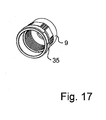
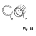
- the nut 9 also has on its outer circumference a groove 34 for receiving a preferably slotted ring 35, which can be used, for example, as a color marking.
- Figs. 14 and 15 also show an alternative embodiment of the collet 10 (here without sealing ring 11).
Landscapes
- Physics & Mathematics (AREA)
- General Physics & Mathematics (AREA)
- Optics & Photonics (AREA)
- Connector Housings Or Holding Contact Members (AREA)
- Mechanical Coupling Of Light Guides (AREA)
- Details Of Connecting Devices For Male And Female Coupling (AREA)
- Input Circuits Of Receivers And Coupling Of Receivers And Audio Equipment (AREA)
- Feeding And Controlling Fuel (AREA)
- Orthopedics, Nursing, And Contraception (AREA)
- Quick-Acting Or Multi-Walled Pipe Joints (AREA)
- Coupling Device And Connection With Printed Circuit (AREA)
- Telephone Function (AREA)
Abstract
Description
Die Erfindung betrifft einen Adapter zur Aufnahme eines Steckerteiles nach dem Oberbegriff des Anspruchs 1.The invention relates to an adapter for receiving a plug part according to the preamble of
Adapter der gattungsgemäßen Art ermöglichen den Einsatz der in sie eingesetzten Steckerteile auch in rauerer Umgebung - beispielsweise in Produktionsanlagen oder Fahrzeugen - durch Erreichen einer im Vergleich zur Schutzklasse des Steckerteils höheren Schutzklasse wie z.B. IP65 oder IP67.Adapters of the generic type allow the use of the connector parts inserted in them even in harsher environment - for example in production plants or vehicles - by achieving a higher than the protection class of the plug part protection class such. IP65 or IP67.
Eine gattungsgemäße Anordnung für einen Telefonstecker ist aus der
Weiterentwickelt bzw. verankert wurde die Idee des Erreichens höher Anforderungen aus Umgebungsklassifikationen in der IEC 61067-3-106 Variante 4, in der EN 50173-1:2005, in der ISO/IEC 24702 und in der IEC 61918.The idea of achieving higher requirements from environmental classifications was further developed or anchored in IEC 61067-3-106
Eine Möglichkeit zur Realisierung dieser Normen zeigt die
Die Erfindung hat daher die Aufgabe, einen verbesserten Adapter zu schaffen, mit dem es möglich ist, mit einfachen konstruktiven Mitteln hohen mechanischen und chemischen Beanspruchungen und Anforderungen gerecht zu werden.The invention therefore has the object to provide an improved adapter, with which it is possible to meet with simple structural means high mechanical and chemical stresses and requirements.
Vorzugsweise soll dabei auch auf einfache Weise eine Aufnahme von Steckerteilen verschiedener Ausgestaltung möglich sein, ohne den Adapter verändern zu müssen. Wünschenswert wäre vorzugsweise eine Nutzbarkeit für:
- Stecker der Datenübertragungstechnik mit Kupfer und/oder Lichtwellenleitern, insbesondere für Ethernet- und Feldbussysteme;
- Stecker der Energieversorgungstechnik mit Kupfer- und/oder Druckluftleitungen; und
- Stecker der Signalübertragungstechnik mit Kupferleitern, insbesondere für Sensoren und/oder Aktoren.
- Plug of data transmission technology with copper and / or optical waveguides, in particular for Ethernet and fieldbus systems;
- Plug of power supply technology with copper and / or compressed air lines; and
- Plug of the signal transmission technology with copper conductors, in particular for sensors and / or actuators.
Die Erfindung löst die oben genannte Aufgabe durch den Gegenstand des Anspruchs 1.The invention achieves the above-mentioned object by the subject matter of
Danach weist das Aufnahmegehäuse einen vorderen Aufnahmeabschnitt für das Steckerteil auf und einen sich daran direkt einstückig anschließenden zylindrischen Abschnitt mit einem sich über einen Teil der axialen Länge erstreckenden Außengewinde zum Aufschrauben einer Mutter für die Kabeldurchführung. Die Mutter weist ferner ein sich über einen Teil ihrer axialen Länge erstreckendes Innengewinde und einen sich über das Gewindeende axial heraus erstreckenden Hülsenabschnitt auf, der einen etwas größeren Innendurchmesser aufweist als der Außendurchmesser des zylindrischen Abschnittes, so dass zwischen dem Innendurchmesser des Hülsenabschnittes und dem Außendurchmesser des zylindrischen Abschnittes ein in Richtung eines Steckgesichtes offener und am anderen Ende von dem verschraubten Gewinde axial verschlossener Ringraum ausgebildet ist, in den ein Hülsenabschnitt einer Schiebehülse oder einer zwischen der Schiebehülse und der Mutter angeordneten Adapterhülse eingreift.Thereafter, the receiving housing on a front receiving portion for the plug part and a directly integrally adjoining cylindrical portion having a part of the axial length extending external thread for screwing a nut for the cable gland. The nut further includes a female thread extending over part of its axial length and a sleeve portion axially extending beyond the threaded end and having a slightly larger inner diameter than the outer diameter of the cylindrical portion such that between the inner diameter of the sleeve portion and the outer diameter of the sleeve portion cylindrical portion is formed in the direction of a mating face open and at the other end of the screwed thread axially sealed annular space in which a sleeve portion of a sliding sleeve or between the sliding sleeve and the nut arranged adapter sleeve engages.
Vorteilhafte Ausgestaltungen sind den Unteransprüchen zu entnehmen.Advantageous embodiments can be found in the dependent claims.
Die Erfindung setzt an der genormten Konstruktion an und entwickelt sie insbesondere im Bereich des abzudichtenden Bereiches zwischen der Mutter der Kabeldurchführung und der Schiebehülse mit einfachen Mitteln in entscheidender Weise derart weiter, dass eine hohe Dichtigkeit und eine mechanische und chemische Resistenz erreicht wird. Der Adapter ist zudem für Steckerteile verschiedenster Art nutzbar, ohne dass zum Erreichen einer hohen Schutzklasse wie IP65 oder IP67 die Konstruktion grundsätzlich geändert werden müsste.The invention is based on the standardized construction and further develops it, in particular in the region of the region to be sealed between the nut of the cable bushing and the sliding sleeve in a decisive manner by simple means in such a way that a high density and a mechanical and chemical resistance is achieved. The adapter can also be used for various types of connector parts, without the design having to be changed to achieve a high degree of protection such as IP65 or IP67.
Es ist gegebenenfalls lediglich notwendig, einen Hilfsrahmen zu verwenden oder Teile des Adapters aus einem bestimmten Material zu fertigen. So können viele der Teile des Adapters entweder aus Kunststoff oder Metall gefertigt werden. Je nach Anforderungsprofil wird die optimale Materialauswahl getroffen.It may only be necessary to use a subframe or to make parts of the adapter of a particular material. So many of the parts of the adapter can be made of either plastic or metal. Depending on the requirement profile, the optimal material selection is made.
Nach einer weiteren vorteilhaften Variante, die auch als unabhängige Erfindung zu verstehen ist, ist das wenigstens eine Steckerteil in einen Hilfsrahmen eingesetzt, welcher in das Aufnahmegehäuse einsetzbar ist. Vorzugsweise ist dabei auch der Hilfsrahmen im Aufnahmegehäuse verrastbar. Der Hilfsrahmen ermöglicht es, auf einfachste Weise verschiedene Steckerelemente in einheitlich gestaltete Aufnahmegehäuse einzusetzen. Die Notwendigkeit zur Bereithaltung verschiedener Aufnahmegehäuse entfällt damit. Es ist auch denkbar, dass einige Steckerteile mit dem Hilfsrahmen befestigbar sind und dass anders gestaltete Steckerteile direkt ohne Hilfsrahmen direkt im Aufnahmegehäuse einsetzbar und dort verrastbar sind.According to a further advantageous variant, which is also to be understood as an independent invention, the at least one plug part is inserted into a subframe, which is insertable into the receiving housing. Preferably, the subframe is latched in the receiving housing. The subframe makes it possible to easily insert different connector elements in a uniformly shaped receiving housing. The need to keep different recording housing is thus eliminated. It is also conceivable that some connector parts can be fastened to the subframe and that differently shaped connector parts can be used directly without subframe directly in the receiving housing and latched there.
Nachfolgend wird die Erfindung unter Bezug auf die Zeichnung anhand von Ausführungsbeispielen näher erläutert, wobei auch weitere Vorteile der Erfindung deutlich werden. Es zeigt:
- Fig. 1
- eine erste perspektivische Ansicht eines Adapterteils, in das ein erstes Datenverarbeitungs-Steckerteil mit elektrischen Kontakten aus dem Büroumfeld eingesetzt ist;
- Fig. 2
- eine Sprengansicht von Elementen der Anordnung aus Fig. 1;
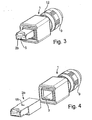
- Fig. 3
- eine erste perspektivische Ansicht eines Adapterteils, in das ein zweites Steckerteil mit elektrischen Kontakten aus dem Industrieumfeld eingesetzt ist;
- Fig. 4
- eine Sprengansicht von Elementen der Anordnung aus Fig. 3;
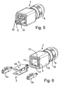
- Fig. 5
- eine erste perspektivische Ansicht eines Adapterteils, in das ein LC-Steckerteil für Kabel mit Lichtwellenleitern eingesetzt ist;
- Fig. 6
- eine Sprengansicht von Elementen der Anordnung aus Fig. 5;
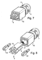
- Fig. 7
- eine erste perspektivische Ansicht eines Adapterteils, in das ein SC-Steckerteil für Kabel mit Lichtwellenleitern eingesetzt ist;
- Fig. 8
- eine Sprengansicht von Elementen der Anordnung aus Fig. 7;
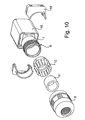
- Fig. 9-11 1
- verschiedene Sprengansichten von Elementen des Adapters aus Fig. 1 aus unterschiedlichen Richtungen; und
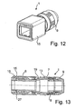
- Fig. 12, 13
- eine perspektivische Ansicht und eine Schnittansicht des zusammengebauten Adapters aus Fig. 1-11; und
- Fig. 14-22
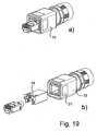
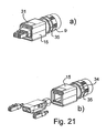
- weitere Ansichten von Adaptern und Elementen von erfindungsgemäßen Adaptern.
- Fig. 1
- a first perspective view of an adapter part, in which a first data processing connector part is inserted with electrical contacts from the office environment;
- Fig. 2
- an exploded view of elements of the arrangement of Fig. 1;
- Fig. 3
- a first perspective view of an adapter part, in which a second plug part is inserted with electrical contacts from the industrial environment;
- Fig. 4
- an exploded view of elements of the arrangement of Fig. 3;
- Fig. 5
- a first perspective view of an adapter part, in which an LC connector part for cables is used with optical fibers;
- Fig. 6
- an exploded view of elements of the arrangement of Fig. 5;
- Fig. 7
- a first perspective view of an adapter part, in which an SC connector part for cables is used with optical fibers;
- Fig. 8
- an exploded view of elements of the arrangement of Fig. 7;
- Fig. 9-11 1
- various explosive views of elements of the adapter of Figure 1 from different directions. and
- Fig. 12, 13
- a perspective view and a sectional view of the assembled adapter of FIG. 1-11; and
- Fig. 14-22
- further views of adapters and elements of adapters according to the invention.
Fig. 1 - 13 zeigen jeweils einen mehrteiligen Adapter 1, in das jeweils ein ein- oder mehrstückiges Steckerteil 2, in Fig. 2 z.B. ein Steckerteil 2a des Büroumfeldes im sogenannten RJ45-Standard, eingesetzt ist. Der Adapter 1 ermöglicht den Einsatz des Steckerteils auch in rauerer Umgebung. Der Begriff Steckerteil ist nicht einschränkend zu verstehen. Es können am Steckerteil Lichtleitelemente, elektrische Stift- und/oder Buchsenkontakte verschiedenster Bauart oder z.B. auch Elemente zur pneumatischen Steckverbindung ausgebildet sein.1 to 13 each show a
Der Aufbau des optimierten erfindungsgemäßen Adapters 1 erschließt sich am besten aus dem Zusammenspiel der Fig. 10 bis 13, wobei zunächst Fig. 11 beschrieben werden soll.The construction of the optimized
Der Adapter weist danach ein Aufnahmegehäuse 3 auf, das zur rastenden Aufnahme des aufzunehmenden Steckerteils 2 direkt (Fig. 4; Steckerteil 2b) oder über einen Hilfs- bzw. Montagerahmen 4 ausgelegt ist (Fig. 2, 6, 8), in welchen zuvor das/die jeweiligen Steckerteil(e) 2a, 2c, 2d eingesetzt wird/werden.The adapter then has a receiving
Das Aufnahmegehäuse 3 ist an seinen beiden Enden hülsenartig offen ausgestaltet.The receiving
Eines der offenen Enden wird im montierten Zustand (siehe Fig. 1, 3, 5, 7) vom Steckgesicht 5 des Steckerteils 2 durchsetzt. Das andere offene Ende ist als Durchführung für ein an das Steckerteil angeschlossenes Kabel (letzteres hier nicht dargestellt) ausgebildet.One of the open ends is in the assembled state (see FIGS. 1, 3, 5, 7) penetrated by the
Das Aufnahmegehäuse 3 weist zur Realisierung dieser Funktionen (siehe Fig. 11 und 13) einen vorderen Aufnahmeabschnitt 6 für das Steckerteil 2 auf und einen sich daran direkt einstückig anschließenden zylindrischen Abschnitt 7 mit einem sich über einen hinteren (am vom Abschnitt 6 abgewandten Ende) Teil seiner axialen Länge erstreckenden Außengewinde 8 zum Aufschrauben einer deckelartigen, sich an ihrem von dem Gewindebereich abgewandten Ende verjüngenden Mutter 9 für die Kabeldurchführung, die korrespondierend ein sich über einen Teil ihrer axialen Länge erstreckendes Innengewinde 26 aufweist.For the realization of these functions (see FIGS. 11 and 13), the receiving
Innerhalb der Mutter 9 können am bzw. im direkten Anschluss an den Abschnitt 7 Funktionselemente wie eine Spannzange bzw. ein Spannring 10 mit einem Dichtring 11 angeordnet sein, die jedenfalls abschnittsweise auch in den Abschnitt 7 eingreifen können. Da sich die Lage der Spannzange 10 mit dem Dichtring 11 damit quasi innerhalb des Gewindes und die Dichtung 11 ganz oder teilweise innerhalb der Spannzange 10 befindet, ist die Länge der Anordnung reduzierbar.Within the
Optional ist ein Knickschutz, insbesondere an oder in der Mutter 9, realisierbar (fig. 14 ff), der z.B. aus Kunststoff oder Metall bestehen kann.Optionally, a kink protection, in particular on or in the
Die Durchführung der erfindungsgemäßen Konstruktion ist ohne weiteres für Kabelmanteldurchmesser von ca. 5 - 10 mm nutzbar.The implementation of the construction according to the invention is readily usable for cable sheath diameter of about 5 - 10 mm.
Die Mutter 9 weist in ihrem zum Steckgesicht hin orientierten Ende einen sich über das Gewindeende axial heraus erstreckenden Hülsenabschnitt 12 auf, der einen etwas größeren Innendurchmesser aufweist als der Außendurchmesser des zylindrischen Abschnittes 7, so dass zwischen dem Innendruchmesser des Hülsenabschnittes 12 und dem Außendurchmesser des zylindrischen Abschnittes 7 ein in Richtung des Steckgesichtes offener und am anderen Ende von dem Gewinde axial verschlossener Ringraum 13 ausgebildet wird (Fig. 11), dem eine zentrale Funktion bei der erreichten Dichtwirkungsoptimierung zukommt (siehe unten), denn es wird ein guter Schutz gegen mechanische und chemische Beanspruchungen realisiert und insbesondere das Eindringen von Schmutz und Feuchtigkeit in den Verriegelungsmechanismus verhindert.The
Das Aufnahmegehäuse 3 weist an seiner Außenfläche hier an zwei gegenüber liegenden Seiten Rasthaken 14 zum Zusammenwirken mit einem hier nicht dargestellten Steckergegenstück auf, welches z.B. nach Art des gattungsgemäßen Standes der Technik aufgebaut sein kann. Die Rasthaken 14 entsprechen der von der eingangs genannten Norm geforderten Ausgestaltung. Ihre Funktion korrespondiert mit der inneren Formgebung einer über das Aufnahmegehäuse 3 schiebbaren Schiebehülse 15, welche das Aufnahmegehäuse 3 hülsenartig geschlossen umgibt und bei einem Rückziehen die Rasthaken 14 in ihre korrespondierenden Ausnehmungen 16 zieht. Rippen 29 in der Schiebehülse 15 dienen der Führung des Steckerteils 2 und/oder als Anschlag für die Bewegung der Schiebehülse 15.The receiving
Die Schiebehülse 15 weist einen im Wesentlichen rechteckigen Querschnitt auf. Zum Steckgesicht 5 hin ist ein Dichtring 27 zwischen der Schiebehülse 15 und dem Aufnahmegehäuse 3 angeordnet.The sliding
An dem Innenumfang und/oder am Außenumfang des Aufnahmegehäuses 3 sind Rastmittel, hier z.B. Rastausnehmungen 17 angeordnet, an denen korrespondierende Rastmittel, hier Rasthaken 18 des Steckerteils oder des Hilfsrahmens 4 verrastbar sind, um das Steckerteil bzw. den Hilfsrahmen am Aufnahmerahmen 3 zu verrasten.On the inner circumference and / or on the outer circumference of the receiving
Das Aufnahmegehäuse 3 kann einen inneren Bund aufweisen, der sich dadurch ergibt, dass die Wände des Aufnahmegehäuses 3 abschnittweise im Einführungsbereich bzw. im Bereich der in Fig. 1 bis 8 vorderen Öffnung dünner ausgestaltet sind, um auch breite Steckerteile in das Aufnahmegehäuse 3 einschieben zu können. Die derart zurückgesetzten Seitenwände führen zu einer verbreiterten Öffnung im vorderen Bereich und erleichtern die Aufnahme breiter Steckerteile und deren Montage/Zuführung.The receiving
Diese Maßnahme trägt auch entscheidend dazu bei, relativ große Steckerteile im Adapter unterbringen zu können.This measure also contributes significantly to be able to accommodate relatively large connector parts in the adapter can.
An die Schiebehülse 15 schließt sich in Richtung der Mutter 9 unmittelbar eine beispielsweise mit der Schiebehülse 15 rastend verbundene Adapterhülse 19 an, die an ihrem einen Ende einen Hülsenabschnitt 20 aufweist, der in den Ringraum 13 innerhalb des Ansatzes der Mutter 9 eingreift. Am anderen Ende greift sie mit einem Bundansatz 21 an Rastmitteln 28 in das axiale Ende der Schiebehülse ein, wobei es ergänzend denkbar ist, dass Dichtringe und/oder weitere Rastmittel die Adapterhülse 19 an der Schiebehülse 15 und/oder der Mutter 9 (im Ringraum 13) sichern.Adjoining the sliding
Die Adapterhülse 19 kann aus zwei leicht montierbaren Halbschalen 22, 23 bestehen, die miteinander beispielsweise über einen Klemmsitz an Stiften 24 und korrespondierenden Sacklöchern 25 verbunden sind. Alternativ ist auch eine einstückige Ausgestaltung realisierbar (nicht dargestellt, z.B. aus Gummi bzw. einem Elastomer), sofern sie montierbar bzw. entformbar bleibt.The
Derart wird auf einfachste Weise insbesondere im Bereich des Ringraumes 13, in welchen die Adapterhülse 19 (bzw. ein Hülsenabschnitt an der Schiebehülse) eingreift, eine gute Schutzwirkung insbesondere gegen das Eindringen von Schmutz und/oder Feuchtigkeit erzielt, die noch von Dichtringen oder weitere Maßnahmen zum Erreichen besonders hoher Schutzklassen gesteigert werden kann.In the simplest way, in particular in the region of the
Optional ist es denkbar, auch die Adapterhülse 19 und die Schiebehülse 15 gemeinsam einstückig auszugestalten (nicht dargestellt). Die Adapterhülse 15, die vorteilhaft und leicht montierbar vorzugsweise aus den zwei Halbschalen 22, 23 besteht, kann ggf. als Zwei-Komponenten-Spritzgießteil mit Dichtringbereichen an ihren Innen- und Außenflächen gefertigt werden.Optionally, it is also conceivable to design the
Nachfolgend werden weitere Vorteile der Konstruktion näher beschrieben.Further advantages of the construction will be described in more detail below.
Da die Steckerteile 2 direkt in dem inneren Aufnahmegehäuse 3 verrastet werden,_ergibt sich eine hohe Stabilität der Verrastung. Die vorstehende Öse nebst zugehöriger Zunge des Standes der Technik, die leicht beschädigt werden können, wird vermieden. Die Rastmittel 17, 18 sind zudem vorteilhaft derart außerhalb des Dichtrings 27 zwischen dem Aufnahmerahmen 3 und der Schiebehülse 15 angeordnet, dass ein Entriegeln bzw. Entrasten von außen möglich ist bzw. bleibt.Since the
Um verschiedene Steckerteile 2 dichtend aufzunehmen, ist es lediglich notwendig, entweder die Steckerteile 2 oder die Hilfsrahmen 4 für die Steckerteile 2 mit den notwendigen Verrastungskonturen bzw. Rastmitteln 18 zur Verrastung an den Rastmitteln 17 zu versehen. Als Rastkonturen bzw. -mittel 18 sind Vorsprünge, Rasthaken, ein Loch, Ausnehmungen usw. denkbar, die am Steckerteil 2 ausgebildet werden und sich korrespondierend am Aufnahmegehäuse 3 wieder finden.In order to receive
Mit Hilfe des Adapters 1 lassen sich derart auf einfache Weise die Aufnahme eines RJ45-Steckers (Bezugszeichen 2a, Fig. 1, 2) aus dem Office-Umfeld unter zu Hilfenahme des Adapters realisieren. Vorzugsweise sind folgende Stecker aufnehmbar:
RJ45 8x AWG 27/7-24/7 (Piercing-Kontakte),RJ45 8xAWG 26/7-22/7 (IDC-Kontakte),- LC-Duplex (Fig. 5 und 6),
- 2 x SC-Simplex-Einsätze (im Abstand eines SC-RJ: 7,35mm: Fig. 7 und 8),
- Power-Kontakte,
- USB,
- Firewire,
- KOAX und/oder
- Sensor-/Aktor-Kontakte.
-
RJ45 8x AWG 27 / 7-24 / 7 (piercing contacts), -
RJ45 8xAWG 26 / 7-22 / 7 (IDC contacts), - LC duplex (Figures 5 and 6),
- 2 x SC Simplex inserts (spaced one SC-RJ: 7.35mm: Figures 7 and 8),
- Power contacts
- USB,
- Firewire,
- COAX and / or
- Sensor / actuator contacts.
Dabei ist die erfindungsgemäße Anordnung insbesondere zum Einsatz im Sensor/Aktor- bzw. Feldbustechnikbereich geeignet.In this case, the arrangement according to the invention is particularly suitable for use in the sensor / actuator or field bus technology area.
Die Schiebehülse 15 sowie die Adapterhülse 19 und/oder die Mutter 9 und/oder ein optionaler Knickschutz sind wie die Steckerteile 2 als Kunststoff- oder Metallteile oder auch als Verbundteile aus mehreren Materialen realisierbar. Bei der Metallausführung bestehen vorzugsweise alle äußeren Gehäuseteile aus Metall (gegen Schweißperlen und hohe mechanische Beanspruchung). Auch die nicht sichtbare, innere Steckeraufnahme bzw. das Aufnahmegehäuse 3 kann aus Metall bestehen, um hohen mechanischen Anforderungen gerecht zu werden. Je nach Anforderung und Anwendung können auch einzelne der Teile des Adapters aus Kunststoff und andere aus Metall bestehen. Am Aufnahmegehäuse 3 aus Metall bestehen vorzugsweise auch die Rasthaken 14 aus Metall, z.B. aus Federstahl, zur Erhöhung der mechanischen Stabilität. Mischformen (Aufnahmegehäuse 3 aus Kunststoff bzw. Metall und die Adapterhülse aus Metall bzw. Kunststoff sind denkbar).The sliding
Die Verriegelungshaken 14 können anstelle über eine Rampe auch über eine Wippe betätigt werden, um die Herstellungskosten zu senken (als low cost - Version, dann ohne Schiebehülse 15 und Adapterhülse 19).The locking hooks 14 can also be actuated by means of a rocker instead of via a ramp in order to reduce the production costs (as a low-cost version, then without a sliding
Dem Adapter kann auch ein Arretierungselement zum Verriegeln der Position der Schiebehülse nach dem Einsetzen des Adapters in die Buchse zugeordnet sein. Das Arretierungselement kann als flexibles Ringsegment aus Kunststoff oder Federstahl ausgebildet sein und nach dem Herstellen der Steckverbindung (Adapter 1 mit Steckerteil 2 in Buchse) zwischen Schiebehülse 15 und Mutter 9 aufschnappbar sein. Eine kodierungsartige Farbgebung kann dann auch durch das bzw. am Arretierungselement realisiert sein (hier alles nicht dargestellt).The adapter may also be assigned a locking element for locking the position of the sliding sleeve after insertion of the adapter into the socket. The locking element may be formed as a flexible ring segment made of plastic or spring steel and after the manufacture of the connector (
Vorteilhaft ist es noch, wenn die Mutter 9 aus Metall besteht und/oder dass an der Mutter 9 einstückig eine Zugentlastung, insbesondere schellenartig, angeordnet oder ausgebildet ist.It is also advantageous if the
Vorzugsweise ist die optische Ebene des Steckerteils nach einer vorteilhaften Variante der Erfindung, die auch als unabhängige Erfindung betrachtet werden kann, derart am Adapter 1 ausgebildet, dass ein kupplungsstückfreier Anschluss der lichtführenden Medien (Glas, HCS, POF) zu einem Transceivergehäuse realisierbar ist (hier nicht dargestellt). Um dies zu erreichen, müssen unterschiedliche Dicken/Stärken von Schrank/Gehäusewänden und unterschiedliche Positionen / Lagen der Transceivergehäuse ausgeglichen werden können. Dies kann funktional gelöst werden, indem die "optische Ebene während der Kabel-/Steckerkonfektion positioniert" werden kann bzw. indem der "Verrastungspunkt des Hilfsrahmens 4 zusätzlich einstellbar im Adapter 1 gestaltet" wird.Preferably, the optical plane of the plug part according to an advantageous variant of the invention, which can also be regarded as an independent invention, so on
Hierzu lässt sich alternativ zur "Standardverrastung in tiefster Position" der Hilfsrahmens 4 auch mit einer abgedichteten Schraube zwischen der Rasthakenbefestigung 14 im Aufnahmegehäuse 3 in nahezu beliebiger Lage weiter vom positionieren und festsetzen; dann erst wird die Schiebehülse 15 und Adapterhülse 19 montiert.For this purpose, as an alternative to "Standardverrastung in the lowest position" of the
Hierzu bietet sich ein korrespondierendes Loch für die Befestigungsschraube an. Die Abdichtung lässt sich durch eine Flachdichtung unter dem teilweise abgesenkten Schraubenkopf realisieren.For this purpose, a corresponding hole for the fastening screw offers. The seal can be realized by a flat gasket under the partially lowered screw head.
Vorzugsweise ist das Aufnahmegehäuse 3 mit einem Befestigungsloch für den Hilfsrahmen 4 optional zur Ausführung ohne Befestigungsloch (aus dem gleichen Umbau-WZ realisierbar) bei sonst gleichem konstruktiven Aufbau und Abmessungen des Adapters 1 unter Erfüllung der IEC 61067-3-106 Variante 4 realisiert. Damit ergibt sich ein kupplungsstückfreier Anschluss der lichtführenden Medien durch freie Positionierbarkeit der optischen Ebene im Adapter mittels Befestigungsschraube.Preferably, the receiving
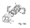
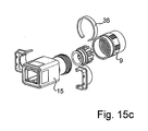
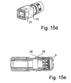
Nach Fig. 14 und 15 und nach einigen der weiteren Figuren sind an der Schiebehülse 15 außen Flächen 31 (Vertiefungen) ausgebildet, die sich zur Aufnahme von Markieren oder dgl. (auch Klebeschildern) eignen.According to Fig. 14 and 15 and according to some of the other figures, surfaces 31 (recesses) are formed on the outside of the sliding
Fig. 14 und 15 sowie einige der weiteren Figuren offenbaren ferner an der Mutter 9 die bereits weiter vom erwähnte Knickschutztülle 32, 33 für ein Kabel am Steckerteil 2, die nach Fig. 14 aus Metall und nach Fig. 15 aus Kunststoff besteht.Figs. 14 and 15 and some of the other figures further disclosed on the
Die Mutter 9 weist ferner an ihrem Außenumfang eine Nut 34 zur Aufnahme eines vorzugsweise geschlitzten Ringes 35 auf, der z.B. als Farbmarkierung nutzbar ist.
Fig. 14 und 15 zeigen auch eine alternative Ausgestaltung der Spannzange 10 (hier ohne Dichtring 11).The
Figs. 14 and 15 also show an alternative embodiment of the collet 10 (here without sealing ring 11).
Claims (39)
dadurch gekennzeichnet, dass
characterized in that
Priority Applications (2)
| Application Number | Priority Date | Filing Date | Title |
|---|---|---|---|
| EP08170586.5A EP2104190B1 (en) | 2005-11-09 | 2006-10-30 | Adapter to accept a plug-in part |
| PL06123126T PL1786071T3 (en) | 2005-11-09 | 2006-10-30 | Adapter for fixing the plug part |
Applications Claiming Priority (3)
| Application Number | Priority Date | Filing Date | Title |
|---|---|---|---|
| DE202005017471 | 2005-11-09 | ||
| DE202006006606 | 2006-04-22 | ||
| DE202006011910U DE202006011910U1 (en) | 2005-11-09 | 2006-08-03 | Adapter for receiving a plug part |
Related Child Applications (1)
| Application Number | Title | Priority Date | Filing Date |
|---|---|---|---|
| EP08170586.5A Division EP2104190B1 (en) | 2005-11-09 | 2006-10-30 | Adapter to accept a plug-in part |
Publications (3)
| Publication Number | Publication Date |
|---|---|
| EP1786071A2 true EP1786071A2 (en) | 2007-05-16 |
| EP1786071A3 EP1786071A3 (en) | 2007-07-11 |
| EP1786071B1 EP1786071B1 (en) | 2009-01-07 |
Family
ID=37762632
Family Applications (2)
| Application Number | Title | Priority Date | Filing Date |
|---|---|---|---|
| EP06123126A Not-in-force EP1786071B1 (en) | 2005-11-09 | 2006-10-30 | Adapter to receive a male connector part |
| EP08170586.5A Active EP2104190B1 (en) | 2005-11-09 | 2006-10-30 | Adapter to accept a plug-in part |
Family Applications After (1)
| Application Number | Title | Priority Date | Filing Date |
|---|---|---|---|
| EP08170586.5A Active EP2104190B1 (en) | 2005-11-09 | 2006-10-30 | Adapter to accept a plug-in part |
Country Status (9)
| Country | Link |
|---|---|
| US (1) | US7367832B2 (en) |
| EP (2) | EP1786071B1 (en) |
| JP (1) | JP4843458B2 (en) |
| AT (1) | ATE420475T1 (en) |
| DE (2) | DE202006011910U1 (en) |
| ES (2) | ES2449238T3 (en) |
| PL (1) | PL1786071T3 (en) |
| RU (1) | RU2408117C2 (en) |
| TW (1) | TWI407645B (en) |
Cited By (3)
| Publication number | Priority date | Publication date | Assignee | Title |
|---|---|---|---|---|
| DE202008014168U1 (en) | 2008-10-24 | 2010-03-11 | Weidmüller Interface GmbH & Co. KG | Plug connection with a male and a female part and these receiving adapter housings |
| DE102008051468A1 (en) | 2008-10-13 | 2010-04-15 | Weidmüller Interface GmbH & Co. KG | Adapter housing for use in production plants or vehicles, has two housing sections formed by insert molding of plugging unit with cable end |
| DE202009015718U1 (en) | 2009-12-10 | 2011-04-21 | Weidmüller Interface GmbH & Co. KG | Plug-in device with an adapter housing |
Families Citing this family (102)
| Publication number | Priority date | Publication date | Assignee | Title |
|---|---|---|---|---|
| US9281637B2 (en) | 2004-08-27 | 2016-03-08 | Ppc Broadband, Inc. | Mini coax cable connector |
| US8142223B2 (en) | 2004-08-27 | 2012-03-27 | Belden Inc. | Universal cable connector with interchangeable color bands |
| US7645161B2 (en) * | 2004-08-27 | 2010-01-12 | International Communication Manufacturing Corp. | Mini-coaxial cable connector assembly with interchargeable color bands |
| US20120009820A1 (en) | 2010-07-09 | 2012-01-12 | Byrne Norman R | Power data housing |
| DE202006009187U1 (en) * | 2006-04-22 | 2007-08-30 | Weidmüller Interface GmbH & Co. KG | Adapter housing for receiving a male or female part |
| US7338214B1 (en) * | 2006-08-25 | 2008-03-04 | Tyco Electronics Corporation | Method and apparatus for sealing fiber optic connectors for industrial applications |
| WO2008112986A1 (en) * | 2007-03-15 | 2008-09-18 | Senko Advanced Components, Inc. | Single boot for duplex fiber optic connectors |
| DE202008005099U1 (en) | 2008-01-21 | 2009-06-18 | Weidmüller Interface GmbH & Co. KG | Plug connection with adapter housings for receiving a plug or a socket arrangement |
| EP2081066B1 (en) | 2008-01-21 | 2019-08-14 | Weidmüller Interface GmbH & Co. KG | Plug-in connection with adapter casings to accept a plug-in or socket arrangement |
| DE202008005100U1 (en) | 2008-01-21 | 2009-06-18 | Weidmüller Interface GmbH & Co. KG | Plug connection with adapter housings for receiving a plug or a socket arrangement |
| DE202008008655U1 (en) | 2008-04-17 | 2009-08-27 | Weidmüller Interface GmbH & Co. KG | Connecting device for connecting electrical consumers |
| USD613246S1 (en) * | 2008-06-10 | 2010-04-06 | Weidmueller Interface Gmbh & Co. Kg | Connector |
| US8152385B2 (en) | 2009-02-27 | 2012-04-10 | Corning Cable Systems Llc | Duplex fiber optic assemblies suitable for polarity reversal and methods therefor |
| CA2707946C (en) | 2009-06-15 | 2013-12-10 | Norman R. Byrne | Power and data adapter assembly |
| US8408815B2 (en) | 2009-06-18 | 2013-04-02 | Senko Advanced Components, Inc. | Optical fiber connector and adapter |
| KR101712822B1 (en) * | 2010-06-11 | 2017-03-07 | 삼성전자주식회사 | Charging device for portable terminal |
| US8573853B2 (en) | 2010-08-23 | 2013-11-05 | Tyco Electronics Corporation | Plug assembly |
| DE102011014012A1 (en) * | 2011-03-09 | 2012-12-27 | Mobotix Ag | Connectors |
| US8646082B2 (en) | 2011-03-17 | 2014-02-04 | Cybernet Systems Corporation | USB firewall apparatus and method |
| US9188747B2 (en) | 2011-05-23 | 2015-11-17 | Senko Advanced Components, Inc. | True one piece housing fiber optic adapter |
| JP2013069550A (en) * | 2011-09-22 | 2013-04-18 | Yamaichi Electronics Co Ltd | Waterproof construction of cable connector, plug connector using the same, and receptacle connector |
| CN103703631B (en) | 2011-10-05 | 2017-02-15 | 扇港元器件有限公司 | Latching connector with remote release |
| FR2989524B1 (en) * | 2012-04-17 | 2015-05-22 | Souriau | QUICK MONOVOY CONNECTION SYSTEM |
| WO2014013612A1 (en) | 2012-07-20 | 2014-01-23 | 三菱電機株式会社 | Connector cover and connector connecting apparatus |
| US8974124B2 (en) | 2012-08-16 | 2015-03-10 | Senko Advanced Components, Inc. | Fiber optic connector |
| US20140060927A1 (en) * | 2012-08-30 | 2014-03-06 | Avc Industrial Corp. | Hook-thread component and wiring element fastening device having the hook-thread component |
| DE102013102023C5 (en) * | 2013-03-01 | 2022-08-18 | Harting Electric Stiftung & Co. Kg | Optical module for modular industrial connectors |
| US10326229B2 (en) | 2013-03-15 | 2019-06-18 | Knxid, Llc | Termination identification device and system |
| US9268103B2 (en) | 2013-05-10 | 2016-02-23 | Senko Advanced Components, Inc. | Interlockable fiber optic connector adaptors |
| US9360649B2 (en) | 2013-05-22 | 2016-06-07 | Senko Advanced Components, Inc. | Cable guide for fiber optic cables |
| CN104884987A (en) * | 2013-07-26 | 2015-09-02 | 京瓷株式会社 | Optical component assembly, optical socket, and transceiver module for optical communication |
| US9618703B2 (en) | 2013-10-03 | 2017-04-11 | Senko Advanced Components, Inc. | Connector housing for securing an optical cable and methods of use and manufacture thereof |
| DE102013112031A1 (en) * | 2013-10-31 | 2015-04-30 | Murrelektronik Gmbh | Housing of a fieldbus module and connectors |
| US9477049B2 (en) | 2013-12-20 | 2016-10-25 | Senko Advanced Components, Inc. | Lockable connectors and connection assemblies |
| US9535230B2 (en) | 2014-01-31 | 2017-01-03 | Senko Advanced Components, Inc. | Integrated fiber optic cable fan-out connector |
| CN109343178A (en) | 2014-02-07 | 2019-02-15 | 泰科电子公司 | Hardened optical power connection system |
| US9297964B2 (en) | 2014-04-18 | 2016-03-29 | Senko Advanced Components, Inc. | Optical fiber connector assembly |
| US9274287B2 (en) | 2014-05-13 | 2016-03-01 | Senko Advanced Components, Inc. | Optical fiber connector and ferrule |
| US9618702B2 (en) | 2014-06-09 | 2017-04-11 | Senko Advanced Components, Inc. | Reduced-profile data transmission element connectors, adapters, and connection assemblies thereof |
| US9450338B2 (en) * | 2014-08-06 | 2016-09-20 | Molex, Llc | High speed connector with ruggedized exterior structure and shielding |
| US9599778B2 (en) | 2014-10-22 | 2017-03-21 | Senko Advanced Components, Inc. | Latching connector with remote release |
| US9494745B2 (en) | 2015-01-16 | 2016-11-15 | Senko Advanced Components, Inc. | Sealable communication cable connection assemblies |
| US9658409B2 (en) | 2015-03-03 | 2017-05-23 | Senko Advanced Components, Inc. | Optical fiber connector with changeable polarity |
| US9755382B2 (en) * | 2015-03-13 | 2017-09-05 | Senko Advanced Components, Inc. | Connector system with interchangeable connector modules for optical fibers, electrical conductors, or both |
| US9684139B2 (en) | 2015-05-29 | 2017-06-20 | Senko Advanced Components, Inc. | Optical fiber connector with changeable gender |
| DE102016101255A1 (en) * | 2016-01-25 | 2017-07-27 | Neutrik Ag | Interconnects |
| DE102016101254A1 (en) * | 2016-01-25 | 2017-07-27 | Neutrik Ag | Interconnects |
| DE102016101506A1 (en) * | 2016-01-28 | 2017-08-03 | Harting Ag & Co. Kg | USB device and USB system |
| US9726830B1 (en) | 2016-06-28 | 2017-08-08 | Senko Advanced Components, Inc. | Connector and adapter system for two-fiber mechanical transfer type ferrule |
| US10228521B2 (en) | 2016-12-05 | 2019-03-12 | Senko Advanced Components, Inc. | Narrow width adapters and connectors with modular latching arm |
| US10078188B1 (en) | 2016-12-05 | 2018-09-18 | Senko Advanced Components, Inc. | Springless push/pull fiber optic connector |
| EP3574356A4 (en) | 2017-01-30 | 2020-08-19 | Senko Advanced Components Inc. | OPTICAL CONNECTORS WITH REVERSIBLE POLARITY |
| US10444444B2 (en) | 2017-01-30 | 2019-10-15 | Senko Advanced Components, Inc. | Remote release tab connector assembly |
| US10725248B2 (en) | 2017-01-30 | 2020-07-28 | Senko Advanced Components, Inc. | Fiber optic receptacle with integrated device therein incorporating a behind-the-wall fiber optic receptacle |
| US10416394B2 (en) | 2017-01-30 | 2019-09-17 | Senko Advanced Components, Inc. | Fiber optic receptacle with integrated device therein |
| US10185100B2 (en) | 2017-01-30 | 2019-01-22 | Senko Advanced Components, Inc | Modular connector and adapter assembly using a removable anchor device |
| US11333836B2 (en) | 2017-01-30 | 2022-05-17 | Senko Advanced Components, Inc. | Adapter for optical connectors |
| US9989712B1 (en) | 2017-03-20 | 2018-06-05 | Senko Advanced Components, Inc | MPO connector assembly with push-pull tab |
| US10209461B2 (en) | 2017-04-07 | 2019-02-19 | Senko Advanced Components | Behind the wall optical connector with reduced components |
| US10754098B2 (en) | 2017-04-07 | 2020-08-25 | Senko Advanced Components, Inc. | Behind the wall optical connector with reduced components |
| US10989884B2 (en) | 2017-04-07 | 2021-04-27 | Senko Advanced Components, Inc. | Behind the wall optical connector with reduced components |
| US10359583B2 (en) | 2017-04-07 | 2019-07-23 | Senko Advanced Components, Inc. | Behind the wall optical connector with reduced components |
| US10401576B2 (en) | 2017-05-10 | 2019-09-03 | Senko Advanced Components, Inc. | MPO micro-latch-lock connector |
| US10146016B1 (en) | 2017-05-10 | 2018-12-04 | Senko Advanced Components, Inc | MPO micro-latchlock connector |
| US10295759B2 (en) | 2017-05-18 | 2019-05-21 | Senko Advanced Components, Inc. | Optical connector with forward-biasing projections |
| US10359576B2 (en) | 2017-06-15 | 2019-07-23 | Senko Advanced Components, Inc. | SC low profile connector with optional boot |
| US11822133B2 (en) | 2017-07-14 | 2023-11-21 | Senko Advanced Components, Inc. | Ultra-small form factor optical connector and adapter |
| US12001064B2 (en) | 2017-07-14 | 2024-06-04 | Senko Advanced Components, Inc. | Small form factor fiber optic connector with multi-purpose boot |
| US10281668B2 (en) | 2017-07-14 | 2019-05-07 | Senko Advanced Components, Inc. | Ultra-small form factor optical connectors |
| US10718911B2 (en) | 2017-08-24 | 2020-07-21 | Senko Advanced Components, Inc. | Ultra-small form factor optical connectors using a push-pull boot receptacle release |
| US10641972B2 (en) | 2017-08-17 | 2020-05-05 | Senko Advanced Components, Inc | Anti-jam alignment sleeve holder or connector housing for a ferrule assembly |
| RU177925U1 (en) * | 2017-09-04 | 2018-03-16 | Акционерное общество "Научно-технический центр "Энергосбережение" | Cable connector |
| US10444442B2 (en) | 2017-11-03 | 2019-10-15 | Senko Advanced Components, Inc. | MPO optical fiber connector |
| US11002923B2 (en) | 2017-11-21 | 2021-05-11 | Senko Advanced Components, Inc. | Fiber optic connector with cable boot release having a two-piece clip assembly |
| US10678000B2 (en) | 2018-01-05 | 2020-06-09 | Senko Advanced Components, Inc. | Pull rod and alignment key for a fiber optic connector and adapter |
| US10234635B1 (en) * | 2018-01-22 | 2019-03-19 | Te Connectivity Corporation | Modular insert assembly |
| US11112566B2 (en) | 2018-03-19 | 2021-09-07 | Senko Advanced Components, Inc. | Removal tool for removing a plural of micro optical connectors from an adapter interface |
| EP3776038B1 (en) | 2018-03-28 | 2024-07-03 | Senko Advanced Components Inc. | Small form factor fiber optic connector with multi-purpose boot |
| US11041993B2 (en) | 2018-04-19 | 2021-06-22 | Senko Advanced Components, Inc. | Fiber optic adapter with removable insert for polarity change and removal tool for the same |
| US10921528B2 (en) | 2018-06-07 | 2021-02-16 | Senko Advanced Components, Inc. | Dual spring multi-fiber optic connector |
| CN112088327A (en) | 2018-07-15 | 2020-12-15 | 扇港元器件股份有限公司 | Subminiature Optical Connectors and Adapters |
| CN108832567A (en) * | 2018-07-16 | 2018-11-16 | 河南联塑实业有限公司 | A kind of transfer joint between wire groove and wire pipe |
| US10444441B1 (en) | 2018-08-10 | 2019-10-15 | Senko Advanced Components, Inc. | Pivotable housing for a fiber optic connector |
| US11073664B2 (en) | 2018-08-13 | 2021-07-27 | Senko Advanced Components, Inc. | Cable boot assembly for releasing fiber optic connector from a receptacle |
| US10921531B2 (en) | 2018-09-12 | 2021-02-16 | Senko Advanced Components, Inc. | LC type connector with push/pull assembly for releasing connector from a receptacle using a cable boot |
| CN112955797B (en) | 2018-09-12 | 2022-11-11 | 扇港元器件股份有限公司 | LC type connector with clip-on push/pull tab for releasing connector from receptacle with cable jacket |
| US10921530B2 (en) | 2018-09-12 | 2021-02-16 | Senko Advanced Components, Inc. | LC type connector with push/pull assembly for releasing connector from a receptacle using a cable boot |
| US10522946B1 (en) * | 2018-09-17 | 2019-12-31 | Hewlett Packard Enterprise Development Lp | Connectors with locking tab |
| US11806831B2 (en) | 2018-11-21 | 2023-11-07 | Senko Advanced Components, Inc. | Fixture and method for polishing fiber optic connector ferrules |
| US11175464B2 (en) | 2018-11-25 | 2021-11-16 | Senko Advanced Components, Inc. | Open ended spring body for use in an optical fiber connector |
| US11689247B2 (en) | 2019-01-16 | 2023-06-27 | Mertek Industries, Llc | Patch cord including wireless components |
| US12038613B2 (en) | 2019-03-28 | 2024-07-16 | Senko Advanced Components, Inc. | Behind-the-wall optical connector and assembly of the same |
| US11340406B2 (en) | 2019-04-19 | 2022-05-24 | Senko Advanced Components, Inc. | Small form factor fiber optic connector with resilient latching mechanism for securing within a hook-less receptacle |
| CN114026480B (en) | 2019-06-13 | 2023-05-26 | 扇港元器件有限公司 | Lever actuated latch arm for releasing fiber optic connectors from receptacle ports and method of use |
| CN114600018B (en) | 2019-07-23 | 2024-04-09 | 扇港元器件有限公司 | Ultra-small receptacle for receiving a fiber optic connector opposite a ferrule assembly |
| WO2021067241A1 (en) | 2019-09-30 | 2021-04-08 | Mertek Industries, Llc | Patch panel traceable networking system |
| CN114787677A (en) | 2019-11-13 | 2022-07-22 | 扇港元器件有限公司 | Optical fiber connector |
| USD1016754S1 (en) * | 2020-08-14 | 2024-03-05 | Maxshine Detailing Llc | Plug and socket combination |
| CN112436337B (en) * | 2020-11-18 | 2023-09-15 | 湖州辰丰线缆有限公司 | Network cable structure and communication device |
| CN114243380B (en) * | 2021-12-10 | 2024-01-12 | 深圳市麦电创新科技有限公司 | Internet remote control type power adapter |
| CN117060127B (en) * | 2023-07-24 | 2025-10-24 | 厦门唯恩电气有限公司 | A connector |
| DE102024111614A1 (en) | 2024-04-25 | 2025-10-30 | Harting Electric Stiftung & Co. Kg | Adapter module for a modular industrial connector |
Citations (2)
| Publication number | Priority date | Publication date | Assignee | Title |
|---|---|---|---|---|
| US4349236A (en) | 1980-10-06 | 1982-09-14 | Bell Telephone Laboratories, Incorporated | Weatherproof electrical jack assembly |
| DE10236275B3 (en) | 2002-08-08 | 2004-01-08 | Harting Electronics Gmbh & Co. Kg | locking device |
Family Cites Families (18)
| Publication number | Priority date | Publication date | Assignee | Title |
|---|---|---|---|---|
| US5212752A (en) * | 1992-05-27 | 1993-05-18 | At&T Bell Laboratories | Optical fiber ferrule connector having enhanced provisions for tuning |
| US5710851A (en) * | 1995-11-06 | 1998-01-20 | Amphenol Corporation | Strain relief system for a fiber optic connector |
| JPH11326684A (en) * | 1998-05-19 | 1999-11-26 | Bridgestone Corp | Mouth piece tool having less optical transmission loss accompanied by connection to optical fiber and capable of being attached to and detached from the optical fiber in a short time and maintaining satisfactory connection state to optical fiber over long time |
| US6010250A (en) * | 1998-07-09 | 2000-01-04 | Sung; Allen L. | Plug for fibre optic cable |
| JP3604314B2 (en) * | 2000-02-03 | 2004-12-22 | 松下電器産業株式会社 | XSR cable connector |
| US6475009B2 (en) * | 2000-06-02 | 2002-11-05 | The Siemon Company | Industrial telecommunications connector |
| JP4081003B2 (en) * | 2001-07-31 | 2008-04-23 | ライヒレ・ウント・デ−マサリ・アクチエンゲゼルシヤフト | Protection device for plug-in connectors |
| US6672774B2 (en) * | 2001-10-05 | 2004-01-06 | Corning Cable Systems Llc | Post-connectorization boot, connectorized fiber optic cable assembly including same, and related methods |
| FR2835657B1 (en) * | 2002-02-05 | 2004-08-06 | Socapex Amphenol | PLUG DEVICE FOR A STANDARD CORD OF ELECTRIC OR OPTICAL LINK |
| FR2835658B1 (en) * | 2002-02-05 | 2007-10-19 | Socapex Amphenol | PLUG DEVICE FOR STANDARD ELECTRICAL CONNECTION CORD |
| DE20213312U1 (en) * | 2002-08-30 | 2004-01-15 | Weidmüller Interface Gmbh & Co. | Connector for connecting an electrical cable |
| US20050064752A1 (en) * | 2003-02-28 | 2005-03-24 | Alden Products Company | Ruggedized ethernet connector assembly |
| JP2004355987A (en) * | 2003-05-30 | 2004-12-16 | Nec Corp | Waterproof modular connector |
| DE102004004229B4 (en) * | 2004-01-27 | 2006-03-02 | Cti Netzwerksysteme Gmbh | Data cable connector module |
| US20060154502A1 (en) * | 2004-12-17 | 2006-07-13 | Cosmo Castaldo | Adapter nut |
| CN100541252C (en) * | 2004-12-20 | 2009-09-16 | 莫莱克斯公司 | Indexed optical fiber connector |
| TWM270530U (en) * | 2005-01-11 | 2005-07-11 | Liang Tei Co Ltd | Waterproof device for electrical plug |
| US20060263011A1 (en) * | 2005-05-20 | 2006-11-23 | Wenzong Chen | Hybrid optical/electrical connector and adapter |
-
2006
- 2006-08-03 DE DE202006011910U patent/DE202006011910U1/en not_active Expired - Lifetime
- 2006-10-24 TW TW095139128A patent/TWI407645B/en not_active IP Right Cessation
- 2006-10-30 EP EP06123126A patent/EP1786071B1/en not_active Not-in-force
- 2006-10-30 PL PL06123126T patent/PL1786071T3/en unknown
- 2006-10-30 EP EP08170586.5A patent/EP2104190B1/en active Active
- 2006-10-30 ES ES08170586.5T patent/ES2449238T3/en active Active
- 2006-10-30 DE DE502006002567T patent/DE502006002567D1/en active Active
- 2006-10-30 ES ES06123126T patent/ES2320925T3/en active Active
- 2006-10-30 AT AT06123126T patent/ATE420475T1/en active
- 2006-11-06 US US11/593,417 patent/US7367832B2/en not_active Expired - Fee Related
- 2006-11-07 RU RU2006138977/28A patent/RU2408117C2/en not_active IP Right Cessation
- 2006-11-09 JP JP2006304436A patent/JP4843458B2/en not_active Expired - Fee Related
Patent Citations (2)
| Publication number | Priority date | Publication date | Assignee | Title |
|---|---|---|---|---|
| US4349236A (en) | 1980-10-06 | 1982-09-14 | Bell Telephone Laboratories, Incorporated | Weatherproof electrical jack assembly |
| DE10236275B3 (en) | 2002-08-08 | 2004-01-08 | Harting Electronics Gmbh & Co. Kg | locking device |
Cited By (5)
| Publication number | Priority date | Publication date | Assignee | Title |
|---|---|---|---|---|
| DE102008051468A1 (en) | 2008-10-13 | 2010-04-15 | Weidmüller Interface GmbH & Co. KG | Adapter housing for use in production plants or vehicles, has two housing sections formed by insert molding of plugging unit with cable end |
| DE102008051468B4 (en) * | 2008-10-13 | 2018-04-12 | Weidmüller Interface GmbH & Co. KG | Adapter housing with a received in the adapter housing plug part and method for its preparation |
| DE202008014168U1 (en) | 2008-10-24 | 2010-03-11 | Weidmüller Interface GmbH & Co. KG | Plug connection with a male and a female part and these receiving adapter housings |
| US8357016B2 (en) | 2008-10-24 | 2013-01-22 | Weidmueller Interface Gmbh & Co. Kg | Plug connector with adapter |
| DE202009015718U1 (en) | 2009-12-10 | 2011-04-21 | Weidmüller Interface GmbH & Co. KG | Plug-in device with an adapter housing |
Also Published As
| Publication number | Publication date |
|---|---|
| EP2104190A3 (en) | 2010-02-03 |
| DE502006002567D1 (en) | 2009-02-26 |
| EP2104190B1 (en) | 2013-12-04 |
| JP4843458B2 (en) | 2011-12-21 |
| EP2104190A2 (en) | 2009-09-23 |
| TWI407645B (en) | 2013-09-01 |
| RU2006138977A (en) | 2008-05-20 |
| RU2408117C2 (en) | 2010-12-27 |
| ATE420475T1 (en) | 2009-01-15 |
| EP1786071A3 (en) | 2007-07-11 |
| ES2449238T3 (en) | 2014-03-18 |
| JP2007134332A (en) | 2007-05-31 |
| US7367832B2 (en) | 2008-05-06 |
| TW200737614A (en) | 2007-10-01 |
| ES2320925T3 (en) | 2009-05-29 |
| DE202006011910U1 (en) | 2007-03-22 |
| EP1786071B1 (en) | 2009-01-07 |
| US20070105432A1 (en) | 2007-05-10 |
| PL1786071T3 (en) | 2009-07-31 |
Similar Documents
| Publication | Publication Date | Title |
|---|---|---|
| EP2104190B1 (en) | Adapter to accept a plug-in part | |
| DE102006000702B4 (en) | connection device | |
| DE102009011388B3 (en) | Connector for optical fibers | |
| EP3453080B1 (en) | Overmoulded connector | |
| DE69934745T2 (en) | Fiber optic coupling sleeve with positioning aid | |
| EP2243050B1 (en) | Cable insertion having upstream mounting fixture | |
| DE202008005099U1 (en) | Plug connection with adapter housings for receiving a plug or a socket arrangement | |
| EP1848068A2 (en) | Adapter for accommodating a male or female connection element | |
| DE202009009807U1 (en) | Tamper-proof cable entry | |
| EP2638603B1 (en) | Sealing contact chambers against injection-moulding material (plastic) during the process of encapsulation by injection moulding | |
| DE69926517T2 (en) | connector | |
| DE102008051468B4 (en) | Adapter housing with a received in the adapter housing plug part and method for its preparation | |
| DE202011003756U1 (en) | Connecting arrangement for the coupling of two electrical connectors together | |
| EP2081066B1 (en) | Plug-in connection with adapter casings to accept a plug-in or socket arrangement | |
| EP1037325A2 (en) | Cable strain relief | |
| EP0957539A2 (en) | Electrical connectors | |
| DE19945173B4 (en) | Connector for at least one optical fiber cable | |
| EP4435981B1 (en) | HOUSING ASSEMBLY FOR A CONNECTOR AND METHOD FOR ASSEMBLING A CONNECTOR | |
| DE102024103689B4 (en) | Cable harness holder with tolerance compensation | |
| EP0847541B1 (en) | Optical plug connector | |
| DE10310749B4 (en) | Electrical connector | |
| EP4435978A1 (en) | Housing assembly for a plug connector and method for assembling a plug connector | |
| WO2024245492A1 (en) | Fastening apparatus for functional units of a multifunctional plug-in connector module, multifunctional plug-in connector module and plug-in connector modular system | |
| DE102016120040B4 (en) | Acorn nut arrangement and cable gland | |
| EP1699115A2 (en) | Plug or coupler of a connection for application in a vehicle |
Legal Events
| Date | Code | Title | Description |
|---|---|---|---|
| PUAI | Public reference made under article 153(3) epc to a published international application that has entered the european phase |
Free format text: ORIGINAL CODE: 0009012 |
|
| AK | Designated contracting states |
Kind code of ref document: A2 Designated state(s): AT BE BG CH CY CZ DE DK EE ES FI FR GB GR HU IE IS IT LI LT LU LV MC NL PL PT RO SE SI SK TR |
|
| AX | Request for extension of the european patent |
Extension state: AL BA HR MK YU |
|
| PUAL | Search report despatched |
Free format text: ORIGINAL CODE: 0009013 |
|
| AK | Designated contracting states |
Kind code of ref document: A3 Designated state(s): AT BE BG CH CY CZ DE DK EE ES FI FR GB GR HU IE IS IT LI LT LU LV MC NL PL PT RO SE SI SK TR |
|
| AX | Request for extension of the european patent |
Extension state: AL BA HR MK YU |
|
| 17P | Request for examination filed |
Effective date: 20070816 |
|
| 17Q | First examination report despatched |
Effective date: 20070924 |
|
| AKX | Designation fees paid |
Designated state(s): AT BE BG CH CY CZ DE DK EE ES FI FR GB GR HU IE IS IT LI LT LU LV MC NL PL PT RO SE SI SK TR |
|
| GRAP | Despatch of communication of intention to grant a patent |
Free format text: ORIGINAL CODE: EPIDOSNIGR1 |
|
| GRAS | Grant fee paid |
Free format text: ORIGINAL CODE: EPIDOSNIGR3 |
|
| GRAA | (expected) grant |
Free format text: ORIGINAL CODE: 0009210 |
|
| AK | Designated contracting states |
Kind code of ref document: B1 Designated state(s): AT BE BG CH CY CZ DE DK EE ES FI FR GB GR HU IE IS IT LI LT LU LV MC NL PL PT RO SE SI SK TR |
|
| REG | Reference to a national code |
Ref country code: GB Ref legal event code: FG4D Free format text: NOT ENGLISH |
|
| REG | Reference to a national code |
Ref country code: CH Ref legal event code: EP |
|
| REG | Reference to a national code |
Ref country code: IE Ref legal event code: FG4D Free format text: LANGUAGE OF EP DOCUMENT: GERMAN |
|
| REF | Corresponds to: |
Ref document number: 502006002567 Country of ref document: DE Date of ref document: 20090226 Kind code of ref document: P |
|
| REG | Reference to a national code |
Ref country code: CH Ref legal event code: NV Representative=s name: ISLER & PEDRAZZINI AG |
|
| REG | Reference to a national code |
Ref country code: SE Ref legal event code: TRGR |
|
| PG25 | Lapsed in a contracting state [announced via postgrant information from national office to epo] |
Ref country code: SI Free format text: LAPSE BECAUSE OF FAILURE TO SUBMIT A TRANSLATION OF THE DESCRIPTION OR TO PAY THE FEE WITHIN THE PRESCRIBED TIME-LIMIT Effective date: 20090107 |
|
| REG | Reference to a national code |
Ref country code: ES Ref legal event code: FG2A Ref document number: 2320925 Country of ref document: ES Kind code of ref document: T3 |
|
| PG25 | Lapsed in a contracting state [announced via postgrant information from national office to epo] |
Ref country code: FI Free format text: LAPSE BECAUSE OF FAILURE TO SUBMIT A TRANSLATION OF THE DESCRIPTION OR TO PAY THE FEE WITHIN THE PRESCRIBED TIME-LIMIT Effective date: 20090107 Ref country code: LT Free format text: LAPSE BECAUSE OF FAILURE TO SUBMIT A TRANSLATION OF THE DESCRIPTION OR TO PAY THE FEE WITHIN THE PRESCRIBED TIME-LIMIT Effective date: 20090107 |
|
| REG | Reference to a national code |
Ref country code: PL Ref legal event code: T3 |
|
| REG | Reference to a national code |
Ref country code: IE Ref legal event code: FD4D |
|
| PG25 | Lapsed in a contracting state [announced via postgrant information from national office to epo] |
Ref country code: PT Free format text: LAPSE BECAUSE OF FAILURE TO SUBMIT A TRANSLATION OF THE DESCRIPTION OR TO PAY THE FEE WITHIN THE PRESCRIBED TIME-LIMIT Effective date: 20090608 Ref country code: LV Free format text: LAPSE BECAUSE OF FAILURE TO SUBMIT A TRANSLATION OF THE DESCRIPTION OR TO PAY THE FEE WITHIN THE PRESCRIBED TIME-LIMIT Effective date: 20090107 Ref country code: IS Free format text: LAPSE BECAUSE OF FAILURE TO SUBMIT A TRANSLATION OF THE DESCRIPTION OR TO PAY THE FEE WITHIN THE PRESCRIBED TIME-LIMIT Effective date: 20090507 |
|
| PG25 | Lapsed in a contracting state [announced via postgrant information from national office to epo] |
Ref country code: DK Free format text: LAPSE BECAUSE OF FAILURE TO SUBMIT A TRANSLATION OF THE DESCRIPTION OR TO PAY THE FEE WITHIN THE PRESCRIBED TIME-LIMIT Effective date: 20090107 Ref country code: IE Free format text: LAPSE BECAUSE OF FAILURE TO SUBMIT A TRANSLATION OF THE DESCRIPTION OR TO PAY THE FEE WITHIN THE PRESCRIBED TIME-LIMIT Effective date: 20090107 Ref country code: EE Free format text: LAPSE BECAUSE OF FAILURE TO SUBMIT A TRANSLATION OF THE DESCRIPTION OR TO PAY THE FEE WITHIN THE PRESCRIBED TIME-LIMIT Effective date: 20090107 |
|
| PLBE | No opposition filed within time limit |
Free format text: ORIGINAL CODE: 0009261 |
|
| STAA | Information on the status of an ep patent application or granted ep patent |
Free format text: STATUS: NO OPPOSITION FILED WITHIN TIME LIMIT |
|
| PG25 | Lapsed in a contracting state [announced via postgrant information from national office to epo] |
Ref country code: SK Free format text: LAPSE BECAUSE OF FAILURE TO SUBMIT A TRANSLATION OF THE DESCRIPTION OR TO PAY THE FEE WITHIN THE PRESCRIBED TIME-LIMIT Effective date: 20090107 Ref country code: RO Free format text: LAPSE BECAUSE OF FAILURE TO SUBMIT A TRANSLATION OF THE DESCRIPTION OR TO PAY THE FEE WITHIN THE PRESCRIBED TIME-LIMIT Effective date: 20090107 |
|
| 26N | No opposition filed |
Effective date: 20091008 |
|
| PG25 | Lapsed in a contracting state [announced via postgrant information from national office to epo] |
Ref country code: BG Free format text: LAPSE BECAUSE OF FAILURE TO SUBMIT A TRANSLATION OF THE DESCRIPTION OR TO PAY THE FEE WITHIN THE PRESCRIBED TIME-LIMIT Effective date: 20090407 |
|
| BERE | Be: lapsed |
Owner name: WEIDMULLER INTERFACE G.M.B.H. & CO. KG Effective date: 20091031 |
|
| PG25 | Lapsed in a contracting state [announced via postgrant information from national office to epo] |
Ref country code: MC Free format text: LAPSE BECAUSE OF NON-PAYMENT OF DUE FEES Effective date: 20091031 |
|
| PG25 | Lapsed in a contracting state [announced via postgrant information from national office to epo] |
Ref country code: BE Free format text: LAPSE BECAUSE OF NON-PAYMENT OF DUE FEES Effective date: 20091031 Ref country code: GR Free format text: LAPSE BECAUSE OF FAILURE TO SUBMIT A TRANSLATION OF THE DESCRIPTION OR TO PAY THE FEE WITHIN THE PRESCRIBED TIME-LIMIT Effective date: 20090408 |
|
| PG25 | Lapsed in a contracting state [announced via postgrant information from national office to epo] |
Ref country code: LU Free format text: LAPSE BECAUSE OF NON-PAYMENT OF DUE FEES Effective date: 20091030 |
|
| PG25 | Lapsed in a contracting state [announced via postgrant information from national office to epo] |
Ref country code: HU Free format text: LAPSE BECAUSE OF FAILURE TO SUBMIT A TRANSLATION OF THE DESCRIPTION OR TO PAY THE FEE WITHIN THE PRESCRIBED TIME-LIMIT Effective date: 20090708 |
|
| PG25 | Lapsed in a contracting state [announced via postgrant information from national office to epo] |
Ref country code: CY Free format text: LAPSE BECAUSE OF FAILURE TO SUBMIT A TRANSLATION OF THE DESCRIPTION OR TO PAY THE FEE WITHIN THE PRESCRIBED TIME-LIMIT Effective date: 20090107 |
|
| REG | Reference to a national code |
Ref country code: FR Ref legal event code: PLFP Year of fee payment: 10 |
|
| PGFP | Annual fee paid to national office [announced via postgrant information from national office to epo] |
Ref country code: PL Payment date: 20150922 Year of fee payment: 10 |
|
| PGFP | Annual fee paid to national office [announced via postgrant information from national office to epo] |
Ref country code: GB Payment date: 20151021 Year of fee payment: 10 Ref country code: DE Payment date: 20151022 Year of fee payment: 10 Ref country code: IT Payment date: 20151028 Year of fee payment: 10 Ref country code: CH Payment date: 20151021 Year of fee payment: 10 |
|
| PGFP | Annual fee paid to national office [announced via postgrant information from national office to epo] |
Ref country code: CZ Payment date: 20151029 Year of fee payment: 10 Ref country code: FR Payment date: 20151023 Year of fee payment: 10 Ref country code: SE Payment date: 20151021 Year of fee payment: 10 Ref country code: AT Payment date: 20151022 Year of fee payment: 10 Ref country code: NL Payment date: 20151021 Year of fee payment: 10 Ref country code: ES Payment date: 20151021 Year of fee payment: 10 |
|
| REG | Reference to a national code |
Ref country code: DE Ref legal event code: R119 Ref document number: 502006002567 Country of ref document: DE |
|
| REG | Reference to a national code |
Ref country code: CH Ref legal event code: PL |
|
| REG | Reference to a national code |
Ref country code: NL Ref legal event code: MM Effective date: 20161101 |
|
| REG | Reference to a national code |
Ref country code: AT Ref legal event code: MM01 Ref document number: 420475 Country of ref document: AT Kind code of ref document: T Effective date: 20161030 |
|
| GBPC | Gb: european patent ceased through non-payment of renewal fee |
Effective date: 20161030 |
|
| REG | Reference to a national code |
Ref country code: FR Ref legal event code: ST Effective date: 20170630 |
|
| PG25 | Lapsed in a contracting state [announced via postgrant information from national office to epo] |
Ref country code: LI Free format text: LAPSE BECAUSE OF NON-PAYMENT OF DUE FEES Effective date: 20161031 Ref country code: GB Free format text: LAPSE BECAUSE OF NON-PAYMENT OF DUE FEES Effective date: 20161030 Ref country code: DE Free format text: LAPSE BECAUSE OF NON-PAYMENT OF DUE FEES Effective date: 20170503 Ref country code: CH Free format text: LAPSE BECAUSE OF NON-PAYMENT OF DUE FEES Effective date: 20161031 Ref country code: CZ Free format text: LAPSE BECAUSE OF NON-PAYMENT OF DUE FEES Effective date: 20161030 Ref country code: FR Free format text: LAPSE BECAUSE OF NON-PAYMENT OF DUE FEES Effective date: 20161102 |
|
| PG25 | Lapsed in a contracting state [announced via postgrant information from national office to epo] |
Ref country code: NL Free format text: LAPSE BECAUSE OF NON-PAYMENT OF DUE FEES Effective date: 20161101 Ref country code: AT Free format text: LAPSE BECAUSE OF NON-PAYMENT OF DUE FEES Effective date: 20161030 Ref country code: SE Free format text: LAPSE BECAUSE OF NON-PAYMENT OF DUE FEES Effective date: 20161031 |
|
| PG25 | Lapsed in a contracting state [announced via postgrant information from national office to epo] |
Ref country code: IT Free format text: LAPSE BECAUSE OF NON-PAYMENT OF DUE FEES Effective date: 20161030 |
|
| PGFP | Annual fee paid to national office [announced via postgrant information from national office to epo] |
Ref country code: TR Payment date: 20151030 Year of fee payment: 10 |
|
| PG25 | Lapsed in a contracting state [announced via postgrant information from national office to epo] |
Ref country code: PL Free format text: LAPSE BECAUSE OF NON-PAYMENT OF DUE FEES Effective date: 20161030 |
|
| PG25 | Lapsed in a contracting state [announced via postgrant information from national office to epo] |
Ref country code: ES Free format text: LAPSE BECAUSE OF NON-PAYMENT OF DUE FEES Effective date: 20161031 |
|
| REG | Reference to a national code |
Ref country code: ES Ref legal event code: FD2A Effective date: 20181126 |
|
| PG25 | Lapsed in a contracting state [announced via postgrant information from national office to epo] |
Ref country code: TR Free format text: LAPSE BECAUSE OF NON-PAYMENT OF DUE FEES Effective date: 20161030 |