EP1786181A2 - Téléphone portable comportant un module coulissant pour faire glisser des boîtiers dans deux directions différentes - Google Patents
Téléphone portable comportant un module coulissant pour faire glisser des boîtiers dans deux directions différentes Download PDFInfo
- Publication number
- EP1786181A2 EP1786181A2 EP06023537A EP06023537A EP1786181A2 EP 1786181 A2 EP1786181 A2 EP 1786181A2 EP 06023537 A EP06023537 A EP 06023537A EP 06023537 A EP06023537 A EP 06023537A EP 1786181 A2 EP1786181 A2 EP 1786181A2
- Authority
- EP
- European Patent Office
- Prior art keywords
- housing
- sliding
- sliding member
- portable terminal
- stopper
- Prior art date
- Legal status (The legal status is an assumption and is not a legal conclusion. Google has not performed a legal analysis and makes no representation as to the accuracy of the status listed.)
- Granted
Links
Images


Classifications
-
- H—ELECTRICITY
- H04—ELECTRIC COMMUNICATION TECHNIQUE
- H04B—TRANSMISSION
- H04B1/00—Details of transmission systems, not covered by a single one of groups H04B3/00 - H04B13/00; Details of transmission systems not characterised by the medium used for transmission
- H04B1/38—Transceivers, i.e. devices in which transmitter and receiver form a structural unit and in which at least one part is used for functions of transmitting and receiving
-
- H—ELECTRICITY
- H04—ELECTRIC COMMUNICATION TECHNIQUE
- H04M—TELEPHONIC COMMUNICATION
- H04M1/00—Substation equipment, e.g. for use by subscribers
- H04M1/02—Constructional features of telephone sets
- H04M1/0202—Portable telephone sets, e.g. cordless phones, mobile phones or bar type handsets
- H04M1/0206—Portable telephones comprising a plurality of mechanically joined movable body parts, e.g. hinged housings
- H04M1/0208—Portable telephones comprising a plurality of mechanically joined movable body parts, e.g. hinged housings characterized by the relative motions of the body parts
- H04M1/0235—Slidable or telescopic telephones, i.e. with a relative translation movement of the body parts; Telephones using a combination of translation and other relative motions of the body parts
- H04M1/0239—Sliding mechanism with two degree of freedom, e.g. translation in two different directions
Definitions
- the present invention relates to a portable terminal. More particularly, the present invention relates to a sliding module for a sliding type portable terminal that allows one housing to slide on the other housing in four directions, that is, upward, downward, right, and left.
- portable terminals may be classified into various types according to their appearance, such as a bar type portable terminal, a flip type portable terminal, or a folder type portable terminal.
- a bar type portable terminal has a single body housing on which a data input/output unit, a transmitter, and a receiver are mounted.
- a keypad used as the data input/output unit always is exposed to the outside, which may result in malfunctions. Further, there is a limit to the miniaturization of the portable terminal because it is difficult to secure an appropriate distance between the transmitter and receiver.
- a flip type portable terminal has a body, a flip, and a hinge module for connecting the flip to the body.
- the body includes a data input/output unit, a transmitter, and a receiver mounted on the body.
- the flip covers the keypad used as the data input unit to prevent malfunctions of the keypad.
- the bar type portable there is a limit to the miniaturization of the flip type portable terminal because it is difficult to secure an appropriate distance between the transmitter and the receiver.
- a folder type portable terminal includes a body, a folder, and a hinge module for rotatably connecting the folder to the body.
- the folder rotates to open and close the body.
- a communication-standby mode in which the folder is closed over the body, it is possible to prevent malfunctions of the keypad.
- a communication mode as the folder is unfolded, it is possible to secure an appropriate distance between the transmitter and the receiver.
- the folder type portable terminals have become increasingly popular because of current market trends favoring smaller portable terminals.
- the flip or the folder type portable terminal when the flip or the folder is rotated over a predetermined angle with respect to the body by the hinge module that rotatably connects the flip or the folder to the body, the flip or the folder is subjected to force in the opening direction even though external force is no longer applied to the flip or the folder.
- the flip or the folder when the flip or the folder is rotated by an angle smaller than the predetermined angle, the flip or the folder is subjected to force in the direction of closing upon the body.
- a sliding type portable terminal includes two housings, one of which slides on the other housing so as to open and close the portable terminal.
- U.S. Patent No. 6,822,871 which issued on November 23, 2004 , is assigned to the same assignee as the present invention, and is hereby incorporated by reference in its entirety, discloses a portable terminal having a pair of housings which are slidably assembled with each other, and a sliding module for the portable terminal.
- one housing movably slides, so as to open and close a part of another housing, particularly a keypad.
- a spring module and a rail-shaped sliding guide are assembled with the housings of the portable terminal, respectively, so as to slidably connect one housing to another housing of the portable terminal.
- the sliding type portable terminals have various sliding modules in which a sliding plate as well as the sliding module having a rail shape are assembled with one housing while the sliding guide is integrated with another housing.
- portable terminals In addition to the further diversification of mobile communication services, portable terminals have become multifunctional. However, portable terminals have not yet diverged from the basic types such as a folder type, a sliding type, and the like. Further, as the use of the portable terminal has become universal, users' tastes also have varied. Nevertheless, the current types of portable terminals do not satisfy users' various tastes.
- An aspect of the present invention is to address at least the above problems and/or disadvantages and to provide at least the advantages described below. Accordingly, an aspect of the present invention is to provide a sliding module for a portable terminal, which the portable terminal to be used in various manners.
- a sliding module for a portable terminal is provided.
- the sliding module is interposed between first and second housings so as to connect the second housing to the first housing so that the second housing is slidable with respect to the first housing.
- the sliding module includes a first sliding member, a second sliding member, first stopper means, and second stopper means.
- the first sliding member is assembled with the first housing for slidably moving the second housing to an upper side or a lower side of the first housing in a first direction.
- the second sliding member is fixed to the second housing and assembled with the first sliding member for slidably moving the second housing to a left or right side of the first housing in a second direction.
- the first stopper means is disposed between the first and second housings for restricting a sliding movement of the second housing in the second direction when the second housing moves to the upper or lower side of the first housing.
- the second stopper means is disposed between the first and second housing for restricting a sliding movement of the second housing in the first direction when the second housing moves to the left or right side of the first housing.
- a sliding module for a portable terminal is provided.
- the sliding module is interposed between first and second housings so as to connect the second housing to the first housing so that the second housing is slidable with respect to the first housing.
- the sliding module includes a guide member fixed to a surface of the first housing, a first sliding member assembled with the guide member so as to slide on the guide member, for slidably moving the second housing to an upper side or a lower side of the first housing in a first direction, and a second sliding member fixed to the second housing and assembled with the first sliding member so as to slide on the first housing, for slidably moving the second housing to a left or right side of the first housing in a second direction.
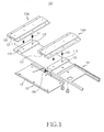
- a sliding module 100 of a portable terminal 200 includes first and second sliding members 101, 102a, and 102b which slide on the first housing 201 of the portable terminal 200. Further, the sliding module 100 may separately include a guide member 103 for assembling the first sliding member 101 with the first housing 201 so that the first sliding member 101 movably slides on the first housing 201.
- the portable terminal 200 includes a first housing 201, and a second housing 202 slidably assembled with the first housing 201.
- the second housing 202 is assembled with the first housing 201 by means of the sliding module 100.
- a transmitter, an input unit (not shown) such as a keypad, a receiver, and an output unit (not shown) such as a display unit of the portable terminal 200 are appropriately arranged on the first and second housing 201 and 202.
- the second housing 202 may movably slide on the first housing 201 in a first direction (X, see FIG. 6) and be located at an upper side or a lower side of the first housing 201.
- the second housing 202 may slide on the first housing 201 in a second direction (Y, see FIG. 8) and be positioned at a right side or a left side.
- the first sliding member 101 has sliding grooves 111 formed along a lengthwise direction on a lower surface thereof, and a guide rail 113 formed on an upper surface thereof.
- the first sliding member 101 is mounted on the first housing 201 and movably slides in a first direction X. At this time, the sliding grooves 111 extend along the first direction X so as to guide the sliding movement of the first sliding member 101.
- the first sliding member 101 is assembled with the first housing 201 of the portable terminal 200 by the guide member 103.
- the guide member 103 is fixed to the first housing 201, and has sliding ribs 131 formed at both edges that extend in the first direction X.
- the sliding ribs 131 are engaged with the sliding grooves 111 of the first sliding member 101.
- the first sliding member 101 can be assembled with the guide member 103 to movably slide along the guide member 103.
- the guide member 103 may be integrally formed on the first housing 201. If the guide member 103 is integrally formed with the first housing, the number of parts can be reduced. Therefore, it is possible to simplify the assembly of the sliding module 100.
- the guide member 103 Since the guide member 103 is assembled with the first sliding member 101 so that the first sliding member 101 movably slides along the guide member 103, while maintaining the combination of the first housing 201 and the first sliding member 101, the guide member 103 may be designed to have greater mechanical strength and durability.
- an elastic member can be interposed between the guide member 103 and the first sliding member 101, so as to provide elasticity for slidably moving the first sliding member 101.
- the elastic member 104 has a first end supported by the guide member 103 and a second end supported by the first sliding member 101, and provides elasticity so that the both ends of the elastic member 104 are spaced away from each other. The area where both ends of the elastic member 104 approach each other is located out of the range in which the first sliding member 101 slides. Therefore, the elastic member 104 biases the first sliding member 101 towards an upper side or a lower side of the guide member 103.
- the second sliding members 102a and 102b are fixed to the second housing 202 and are also assembled with the first sliding member 101, so as to movably slide in the second direction Y.
- the guide rails 113 of the first sliding member 101 are assembled with the second sliding members 102a and 102b, and extend in the second direction Y.
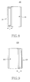
- the second sliding member 102 has a guide groove 121 formed on a surface thereof, and is engaged with the guide rail 113 so as to slidably contact the guide rail.
- the second sliding members 102a and 102b are assembled with the first sliding member 101 by means of the guide rail 113 and the guide groove 121, so as to movably slide in the second direction Y.
- Pairs of recesses 125 are formed in the guide groove 121 in the second direction Y.
- At least one ball 153 (which may be formed of metal) is installed in the first sliding member 101, particularly guide rail 113, so as to move in and out the first sliding member 101.
- the guide rail 113 has receiving grooves 115 which receive the balls 153.
- coil springs 151 are received in the receiving grooves 115 respectively, so as to bias the balls 153 in a direction that the balls 153 protrude on the guide rail 113.
- two pairs of grooves 125 are provided.
- the pairs of balls 153 are mounted on the guide rails 113, respectively.
- the second sliding members 102a and 102b move in the second direction Y, one pair of grooves 125 among the pairs of grooves 125 are engaged with the balls 153 while facing the balls 153.
- the two sliding members 102a and 102b are assembled with the first sliding member 101, one of which is located at an upper side, and the other of which is located at a lower side of the first sliding member 101.
- the second sliding members 102a and 102b need not be configured as a pair.
- any one of the sliding members 102a and 102b is mounted on the first sliding member 101, it is possible to realize the sliding movement of the second housing 202 in the second direction Y. Further, it will be understood by persons skilled in the art that plural pairs of second sliding members 102a and 102b may be used.
- the sliding module 100 is provided with stopper members to restrict the sliding movement of the second housing 202 in a direction from one position to another position, based on a position to which the second housing 202 moves.
- the stopper members include a first stopper member and a second stopper member.
- the first stopper member restricts the sliding movement of the second housing 202 in the second direction Y when the second housing 202 moves in the first direction X so as to reach the upper side or lower side of the first housing 201
- the second stopper member restricts the sliding movement of the second housing 202 in the first direction X when the second housing moves in the second direction Y so as to reach the left side or the right side of the first housing 201.
- the first stopper member includes at least one pair of first stopper ribs 161a and 161b formed on the first housing 201, and first stopper grooves 127 formed in the lower member 102a of the second sliding members 102a and 102b.
- first stopper grooves 127 formed in the lower member 102a of the second sliding members 102a and 102b are used to realize the function of the first stopper member. This is because the upper member 102b of the second sliding members 102a and 102b cannot carry out the function of the stopper when the second housing 202 moves toward the upper side of the first housing 201 so that the upper member 102b of the second sliding members 102a and 102b does not face the first housing 201.
- the first stopper ribs 161a and 161b, and the first stopper grooves 127 respectively extend in the first direction X. Therefore, when the first stopper ribs 161a and 161b are engaged with the first stopper grooves 127, the movement of the second housing 202 in the second direction Y is restricted, but the second housing 202 may move in the first direction X.
- the first stopper ribs 161 a and 161b are formed at an upper portion and an intermediate portion of the first housing 201.
- the second sliding member 102a located at a lower side of the second housing 202 faces the first stopper rib 161 a located at an upper side of the first housing 101.
- the second sliding member faces the first stopper rib 161b located at a lower side of the first sliding member 201.
- One of the first stopper ribs 161a and 161b faces the second sliding member 102a located at a lower side of the second housing 201 so as to be engaged with the first stopper groove 127.
- FIGS. 6 and 7 show the movement of the second housing 202 toward the upper or lower side of the first housing along the first direction X. As shown in FIGS. 6 and 7, the second housing 202 may have a longer upward movement distance than a downward movement distance. Thus, when the second housing 202 overlaps with the first housing 201, the first stopper rib 161a located at the upper side of the first housing 201 is farther away from the second sliding member 102a located at a lower side of the second housing 202.
- the second sliding member 102b faces the first stopper rib 161 a. Therefore, when the second sliding member 102b and the first stopper rib 161b interfere with each other, the sliding movement of the second housing 202 in the second direction Y is restricted.
- an avoidance groove 123 is formed in the second sliding member 102b located at the upper side of the second housing 202, while a groove having a desired shape is formed in the first stopper rib 161 a.
- An upper portion protruding from the first stopper rib 161 a is located in the avoidance groove 123, and a portion protruding above the avoidance groove 123 from the second sliding member 102b is located at a portion in which a groove is formed. Therefore, it is possible to prevent interference between the second sliding member 102b and the first stopper rib 161 a when the second housing 202 overlaps with the first housing 201.
- the second sliding member 102a is restricted by an upper portion protruding from the first stopper rib 161 a and cannot movably slide in the second direction. Specifically, when the second housing 202 moves toward the upper side of the first housing 201, the upper portion protruding from the first stopper rib 161a is engaged with the first stopper groove 127 of the second sliding member 102a.
- the second stopper member includes a second stopper groove 165 (see FIG. 4) formed in one of the first and second housings 201 and 202, and a second stopper rib 163 (see FIG. 4) formed in the other housing.
- the second stopper groove 165 is formed in the second housing 202
- the second stopper rib 163 is formed in the first housing 201.
- the second stopper rib 163 is formed at an upper center of the first housing 201, and the second stopper groove 165 is formed at an upper end of the second housing 202 so as to extend in the second direction Y.
- the second stopper groove 165 is partially opened at the center portion thereof in the first direction X, so as not to interfere with the second stopper rib 163 when the second housing 202 overlaps with the first housing 201 while moving upward or downward.
- the portable terminal 200 having the sliding module 100 configured as described above may operate in different modes depending on the position of the second housing 202. Specifically, if the second housing 202 moves to the upper side of the first housing 201, the portable terminal operates in the communication mode. On the other hand, if the second housing 202 moves to the lower side of the first housing 201, the portable terminal operates in a photographing mode. In addition, if the second housing 202 moves to the left or right side of the first housing 201, the portable terminal operates in a broadcast reception mode or sound reproduction mode.
- the sliding module for the portable terminal allows one of housings to move on the other housing in four-ways, that is, in upward, downward, left, and right directions, thereby diversifying the types of the portable terminals.
- the portable terminal may operate in different modes depending on the movement direction of the housing thereof, so that a user can conveniently operate the portable terminal.
Landscapes
- Engineering & Computer Science (AREA)
- Signal Processing (AREA)
- Computer Networks & Wireless Communication (AREA)
- Telephone Set Structure (AREA)
Applications Claiming Priority (1)
| Application Number | Priority Date | Filing Date | Title |
|---|---|---|---|
| KR1020050108254A KR100713421B1 (ko) | 2005-11-11 | 2005-11-11 | 휴대용 단말기의 슬라이딩 모듈 |
Publications (3)
| Publication Number | Publication Date |
|---|---|
| EP1786181A2 true EP1786181A2 (fr) | 2007-05-16 |
| EP1786181A3 EP1786181A3 (fr) | 2011-06-22 |
| EP1786181B1 EP1786181B1 (fr) | 2017-02-22 |
Family
ID=37719358
Family Applications (1)
| Application Number | Title | Priority Date | Filing Date |
|---|---|---|---|
| EP06023537.1A Expired - Fee Related EP1786181B1 (fr) | 2005-11-11 | 2006-11-13 | Téléphone portable comportant un module coulissant pour faire glisser des boîtiers dans deux directions différentes |
Country Status (4)
| Country | Link |
|---|---|
| US (1) | US8014840B2 (fr) |
| EP (1) | EP1786181B1 (fr) |
| KR (1) | KR100713421B1 (fr) |
| CN (1) | CN1964377B (fr) |
Cited By (3)
| Publication number | Priority date | Publication date | Assignee | Title |
|---|---|---|---|---|
| EP1903754A1 (fr) * | 2006-09-19 | 2008-03-26 | Samsung Electronics Co., Ltd. | Module coulissant pour terminal de communication portable à double coulissement |
| EP2007116A2 (fr) * | 2007-06-22 | 2008-12-24 | Samsung Electronics Co., Ltd. | Utilisation du mouvement des boîtiers coulissants comme entrée dans un telephone portable |
| EP2151975A1 (fr) | 2008-08-07 | 2010-02-10 | Hanbit Precision Co., Ltd. | Module de charnière coulissante pour téléphone mobile |
Families Citing this family (9)
| Publication number | Priority date | Publication date | Assignee | Title |
|---|---|---|---|---|
| KR100833241B1 (ko) * | 2006-04-28 | 2008-05-28 | 삼성전자주식회사 | 슬라이딩-틸트장치 및 이를 채용한 모바일 기기 |
| KR100756907B1 (ko) * | 2006-10-24 | 2007-09-07 | 주식회사 엠투시스 | 전자기기용 개폐장치의 슬라이딩 구조 |
| KR20100075443A (ko) * | 2007-10-26 | 2010-07-02 | 가부시키가이샤 스트로베리 코포레이션 | 슬라이드 장치 및 슬라이드 장치를 이용한 전자 기기 |
| KR101063028B1 (ko) * | 2008-04-23 | 2011-09-07 | 한 상 이 | 슬라이드식 개폐장치 및 슬라이드 개폐식 휴대형 전자기기 |
| KR101604703B1 (ko) | 2008-09-26 | 2016-03-25 | 엘지전자 주식회사 | 슬라이드 모듈 및 그를 구비하는 휴대 단말기 |
| KR101587087B1 (ko) * | 2008-10-14 | 2016-02-02 | 엘지전자 주식회사 | 휴대 단말기 |
| KR101214707B1 (ko) | 2008-12-19 | 2012-12-21 | 노키아 코포레이션 | 휴대용 전자 디바이스용 장치 및 그 조립 방법 |
| US9385771B2 (en) * | 2010-01-22 | 2016-07-05 | Blackberry Limited | Release mechanism for a smart card |
| CN102200837B (zh) * | 2011-05-26 | 2013-08-07 | 苏州达方电子有限公司 | 输入装置 |
Citations (2)
| Publication number | Priority date | Publication date | Assignee | Title |
|---|---|---|---|---|
| US20040198246A1 (en) | 2003-01-15 | 2004-10-07 | Yuh-Huei Tsai | [handheld electronic device] |
| EP1592209A2 (fr) | 2004-04-29 | 2005-11-02 | Samsung Electronics Co., Ltd. | Appareil de communication portable de type coulissant double |
Family Cites Families (9)
| Publication number | Priority date | Publication date | Assignee | Title |
|---|---|---|---|---|
| JPH10207616A (ja) * | 1997-01-20 | 1998-08-07 | Sharp Corp | 入力装置 |
| US20050091431A1 (en) * | 2003-10-23 | 2005-04-28 | Robert Olodort | Portable communication devices |
| US20050125570A1 (en) | 2003-10-23 | 2005-06-09 | Robert Olodort | Portable communication devices |
| KR20050038982A (ko) * | 2003-10-23 | 2005-04-29 | 삼성전자주식회사 | 슬라이딩/스윙 타입 휴대용 디지털 통신 장치 |
| US7907121B2 (en) * | 2003-11-19 | 2011-03-15 | Qualcomm Incorporated | Portable device with versatile keyboard |
| US20050245294A1 (en) | 2004-03-30 | 2005-11-03 | Amphenol-T&M Antennas. | Dual axis hinge for handheld device |
| KR100616197B1 (ko) * | 2004-08-24 | 2006-08-25 | 삼성전자주식회사 | 이중 슬라이딩 타입 휴대용 통신 장치의 슬라이딩 장치 |
| US7671836B2 (en) * | 2005-01-03 | 2010-03-02 | Nokia Corporation | Cell phone with shiftable keypad |
| KR100628384B1 (ko) * | 2005-05-31 | 2006-09-28 | 주식회사 팬택 | 동시오픈 방지 구조를 가진 이중방향 슬라이드 타입 휴대폰 |
-
2005
- 2005-11-11 KR KR1020050108254A patent/KR100713421B1/ko not_active Expired - Fee Related
-
2006
- 2006-10-02 US US11/540,584 patent/US8014840B2/en not_active Expired - Fee Related
- 2006-11-13 EP EP06023537.1A patent/EP1786181B1/fr not_active Expired - Fee Related
- 2006-11-13 CN CN2006101470461A patent/CN1964377B/zh not_active Expired - Fee Related
Patent Citations (2)
| Publication number | Priority date | Publication date | Assignee | Title |
|---|---|---|---|---|
| US20040198246A1 (en) | 2003-01-15 | 2004-10-07 | Yuh-Huei Tsai | [handheld electronic device] |
| EP1592209A2 (fr) | 2004-04-29 | 2005-11-02 | Samsung Electronics Co., Ltd. | Appareil de communication portable de type coulissant double |
Cited By (5)
| Publication number | Priority date | Publication date | Assignee | Title |
|---|---|---|---|---|
| EP1903754A1 (fr) * | 2006-09-19 | 2008-03-26 | Samsung Electronics Co., Ltd. | Module coulissant pour terminal de communication portable à double coulissement |
| US7853301B2 (en) | 2006-09-19 | 2010-12-14 | Samsung Electronics Co., Ltd | Sliding module for double sliding-type portable communication terminal |
| EP2007116A2 (fr) * | 2007-06-22 | 2008-12-24 | Samsung Electronics Co., Ltd. | Utilisation du mouvement des boîtiers coulissants comme entrée dans un telephone portable |
| US7801580B2 (en) * | 2007-06-22 | 2010-09-21 | Samsung Electronics Co., Ltd. | Portable electronic device |
| EP2151975A1 (fr) | 2008-08-07 | 2010-02-10 | Hanbit Precision Co., Ltd. | Module de charnière coulissante pour téléphone mobile |
Also Published As
| Publication number | Publication date |
|---|---|
| CN1964377B (zh) | 2012-06-13 |
| CN1964377A (zh) | 2007-05-16 |
| US8014840B2 (en) | 2011-09-06 |
| EP1786181B1 (fr) | 2017-02-22 |
| KR100713421B1 (ko) | 2007-05-04 |
| EP1786181A3 (fr) | 2011-06-22 |
| US20070107922A1 (en) | 2007-05-17 |
Similar Documents
| Publication | Publication Date | Title |
|---|---|---|
| US7184806B2 (en) | Sliding module for mobile terminal | |
| KR100617690B1 (ko) | 슬라이딩 타입 휴대용 무선 단말기 | |
| EP1422911A2 (fr) | Terminal portable et sans fil de type coulissant | |
| EP1583328A1 (fr) | Terminal coulissant mobile de télécommunication avec mécanisme de glissement | |
| EP1648145B1 (fr) | Module de coulissement pour un terminal portable du type coulissant | |
| US20080234014A1 (en) | Sliding-type portable terminal | |
| EP1871076A1 (fr) | Module coulissant pour téléphone mobile | |
| EP1786181B1 (fr) | Téléphone portable comportant un module coulissant pour faire glisser des boîtiers dans deux directions différentes | |
| US7157648B2 (en) | Sliding module for portable terminal | |
| EP1783983B1 (fr) | Module coulissant pour un terminal mobile | |
| EP1809007B1 (fr) | Terminal portable comportant un module à glissière | |
| US7869846B2 (en) | Sliding module for sliding-type portable terminal | |
| EP1734725B1 (fr) | Terminal portable avec module de coulissement | |
| KR100616654B1 (ko) | 경사식 슬라이드형 이동통신단말기 | |
| KR100651406B1 (ko) | 휴대용 단말기의 슬라이딩 모듈 | |
| KR101138068B1 (ko) | 슬라이딩 모듈을 구비하는 휴대용 단말기 | |
| KR20090047416A (ko) | 휴대폰용 슬림 슬라이드 힌지 어셈블리 | |
| KR100713375B1 (ko) | 휴대용 단말기의 슬라이딩 모듈 | |
| KR100754620B1 (ko) | 슬라이딩 모듈을 구비하는 휴대용 단말기 | |
| KR200376765Y1 (ko) | 휴대용 단말기의 슬라이딩 모듈 | |
| KR20050093049A (ko) | 휴대용 단말기의 슬라이딩 모듈 | |
| KR20050066793A (ko) | 슬라이딩방식 이동통신 단말기의 슬라이딩장치 | |
| KR20080006728A (ko) | 슬라이딩 타입 휴대용 단말기 | |
| KR20060047119A (ko) | 슬라이딩 타입 휴대용 단말기의 슬라이딩 모듈 | |
| HK1088474A (en) | Slide type mobile phone module |
Legal Events
| Date | Code | Title | Description |
|---|---|---|---|
| PUAI | Public reference made under article 153(3) epc to a published international application that has entered the european phase |
Free format text: ORIGINAL CODE: 0009012 |
|
| 17P | Request for examination filed |
Effective date: 20061113 |
|
| AK | Designated contracting states |
Kind code of ref document: A2 Designated state(s): AT BE BG CH CY CZ DE DK EE ES FI FR GB GR HU IE IS IT LI LT LU LV MC NL PL PT RO SE SI SK TR |
|
| AX | Request for extension of the european patent |
Extension state: AL BA HR MK YU |
|
| PUAL | Search report despatched |
Free format text: ORIGINAL CODE: 0009013 |
|
| AK | Designated contracting states |
Kind code of ref document: A3 Designated state(s): AT BE BG CH CY CZ DE DK EE ES FI FR GB GR HU IE IS IT LI LT LU LV MC NL PL PT RO SE SI SK TR |
|
| AX | Request for extension of the european patent |
Extension state: AL BA HR MK RS |
|
| AKX | Designation fees paid |
Designated state(s): DE FR GB |
|
| 17Q | First examination report despatched |
Effective date: 20120523 |
|
| RAP1 | Party data changed (applicant data changed or rights of an application transferred) |
Owner name: SAMSUNG ELECTRONICS CO., LTD. |
|
| GRAP | Despatch of communication of intention to grant a patent |
Free format text: ORIGINAL CODE: EPIDOSNIGR1 |
|
| INTG | Intention to grant announced |
Effective date: 20160907 |
|
| GRAS | Grant fee paid |
Free format text: ORIGINAL CODE: EPIDOSNIGR3 |
|
| GRAA | (expected) grant |
Free format text: ORIGINAL CODE: 0009210 |
|
| AK | Designated contracting states |
Kind code of ref document: B1 Designated state(s): DE FR GB |
|
| REG | Reference to a national code |
Ref country code: GB Ref legal event code: FG4D |
|
| REG | Reference to a national code |
Ref country code: DE Ref legal event code: R096 Ref document number: 602006051757 Country of ref document: DE |
|
| REG | Reference to a national code |
Ref country code: DE Ref legal event code: R097 Ref document number: 602006051757 Country of ref document: DE |
|
| PLBE | No opposition filed within time limit |
Free format text: ORIGINAL CODE: 0009261 |
|
| STAA | Information on the status of an ep patent application or granted ep patent |
Free format text: STATUS: NO OPPOSITION FILED WITHIN TIME LIMIT |
|
| 26N | No opposition filed |
Effective date: 20171123 |
|
| REG | Reference to a national code |
Ref country code: FR Ref legal event code: ST Effective date: 20180731 |
|
| PG25 | Lapsed in a contracting state [announced via postgrant information from national office to epo] |
Ref country code: FR Free format text: LAPSE BECAUSE OF NON-PAYMENT OF DUE FEES Effective date: 20171130 |
|
| PGFP | Annual fee paid to national office [announced via postgrant information from national office to epo] |
Ref country code: DE Payment date: 20191021 Year of fee payment: 14 |
|
| PGFP | Annual fee paid to national office [announced via postgrant information from national office to epo] |
Ref country code: GB Payment date: 20191023 Year of fee payment: 14 |
|
| REG | Reference to a national code |
Ref country code: DE Ref legal event code: R119 Ref document number: 602006051757 Country of ref document: DE |
|
| GBPC | Gb: european patent ceased through non-payment of renewal fee |
Effective date: 20201113 |
|
| PG25 | Lapsed in a contracting state [announced via postgrant information from national office to epo] |
Ref country code: GB Free format text: LAPSE BECAUSE OF NON-PAYMENT OF DUE FEES Effective date: 20201113 Ref country code: DE Free format text: LAPSE BECAUSE OF NON-PAYMENT OF DUE FEES Effective date: 20210601 |