EP1809007B1 - Terminal portable comportant un module à glissière - Google Patents
Terminal portable comportant un module à glissière Download PDFInfo
- Publication number
- EP1809007B1 EP1809007B1 EP07100114A EP07100114A EP1809007B1 EP 1809007 B1 EP1809007 B1 EP 1809007B1 EP 07100114 A EP07100114 A EP 07100114A EP 07100114 A EP07100114 A EP 07100114A EP 1809007 B1 EP1809007 B1 EP 1809007B1
- Authority
- EP
- European Patent Office
- Prior art keywords
- guide
- sliding
- housing
- portable terminal
- plate
- Prior art date
- Legal status (The legal status is an assumption and is not a legal conclusion. Google has not performed a legal analysis and makes no representation as to the accuracy of the status listed.)
- Ceased
Links
Images


Classifications
-
- B—PERFORMING OPERATIONS; TRANSPORTING
- B24—GRINDING; POLISHING
- B24B—MACHINES, DEVICES, OR PROCESSES FOR GRINDING OR POLISHING; DRESSING OR CONDITIONING OF ABRADING SURFACES; FEEDING OF GRINDING, POLISHING, OR LAPPING AGENTS
- B24B3/00—Sharpening cutting edges, e.g. of tools; Accessories therefor, e.g. for holding the tools
- B24B3/24—Sharpening cutting edges, e.g. of tools; Accessories therefor, e.g. for holding the tools of drills
-
- H—ELECTRICITY
- H04—ELECTRIC COMMUNICATION TECHNIQUE
- H04M—TELEPHONIC COMMUNICATION
- H04M1/00—Substation equipment, e.g. for use by subscribers
- H04M1/02—Constructional features of telephone sets
- H04M1/0202—Portable telephone sets, e.g. cordless phones, mobile phones or bar type handsets
- H04M1/0206—Portable telephones comprising a plurality of mechanically joined movable body parts, e.g. hinged housings
- H04M1/0208—Portable telephones comprising a plurality of mechanically joined movable body parts, e.g. hinged housings characterized by the relative motions of the body parts
- H04M1/0235—Slidable or telescopic telephones, i.e. with a relative translation movement of the body parts; Telephones using a combination of translation and other relative motions of the body parts
- H04M1/0237—Sliding mechanism with one degree of freedom
-
- B—PERFORMING OPERATIONS; TRANSPORTING
- B24—GRINDING; POLISHING
- B24B—MACHINES, DEVICES, OR PROCESSES FOR GRINDING OR POLISHING; DRESSING OR CONDITIONING OF ABRADING SURFACES; FEEDING OF GRINDING, POLISHING, OR LAPPING AGENTS
- B24B27/00—Other grinding machines or devices
- B24B27/0084—Other grinding machines or devices the grinding wheel support being angularly adjustable
-
- B—PERFORMING OPERATIONS; TRANSPORTING
- B24—GRINDING; POLISHING
- B24B—MACHINES, DEVICES, OR PROCESSES FOR GRINDING OR POLISHING; DRESSING OR CONDITIONING OF ABRADING SURFACES; FEEDING OF GRINDING, POLISHING, OR LAPPING AGENTS
- B24B3/00—Sharpening cutting edges, e.g. of tools; Accessories therefor, e.g. for holding the tools
- B24B3/24—Sharpening cutting edges, e.g. of tools; Accessories therefor, e.g. for holding the tools of drills
- B24B3/247—Supports for drills
-
- B—PERFORMING OPERATIONS; TRANSPORTING
- B24—GRINDING; POLISHING
- B24B—MACHINES, DEVICES, OR PROCESSES FOR GRINDING OR POLISHING; DRESSING OR CONDITIONING OF ABRADING SURFACES; FEEDING OF GRINDING, POLISHING, OR LAPPING AGENTS
- B24B41/00—Component parts such as frames, beds, carriages, headstocks
- B24B41/06—Work supports, e.g. adjustable steadies
-
- B—PERFORMING OPERATIONS; TRANSPORTING
- B24—GRINDING; POLISHING
- B24B—MACHINES, DEVICES, OR PROCESSES FOR GRINDING OR POLISHING; DRESSING OR CONDITIONING OF ABRADING SURFACES; FEEDING OF GRINDING, POLISHING, OR LAPPING AGENTS
- B24B47/00—Drives or gearings; Equipment therefor
- B24B47/22—Equipment for exact control of the position of the grinding tool or work at the start of the grinding operation
Definitions
- the present invention relates to a portable terminal, and more particularly to a portable terminal having a first housing and a second housing adapted to slide in the longitudinal direction of the first housing so as to expose/hide a portion of the first housing.
- portable terminals are classified into bar-type terminals, flip-type terminals, and folder-type terminals according to their appearance.
- the bar-type terminals have data input/output means and transmitter/receiver units mounted on a single housing. They have a problem in that the data input means, particularly a keypad, is exposed all the time and is vulnerable to erroneous operation. In addition, the requirement that a distance must be maintained between the transmitter and receiver units limits the degree of compactness of the terminals.
- the flip-type terminals have a body, a flip, and a hinge module for connecting the body and the flip to each other.
- the body is provided with data input/output means and transmitter/receiver units.
- the flip covers the data input means, particularly a keypad, and prevents erroneous operation.
- the degree of compactness of the flip-type terminals is limited by the need to utilize the body to maintain the distance between the transmitter and receiver units, as done in bar-type terminals.
- the folder-type terminals have a body, a folder, and a hinge module for rotatably connecting the body and the folder to each other so that the folder is rotated so as to open/close the terminals.
- the folder In a standby mode, the folder is folded on the body and prevents erroneous operation of the keypad.
- the folder In a speech mode, the folder is unfolded from the body so as to secure a sufficient distance between the transmitter and receiver units.
- the folder-type terminals are advantageous to compactness and, for this reason, have prevailed in the portable terminal industry.
- the flip or folder receives force from the hinge module, which rotatably connects the flip or folder to the bodying such a manner that, if the flip or folder has been rotated to a predetermined angle, it is automatically unfolded without additional force and, if not, it remains folded on the body.
- the sliding-type terminals have two housings, one of which is adapted to slide on the other so as to open/close the terminals.
- EP-A-1 530 345 refers to a sliding-type mobile communication terminal.
- the sliding-type mobile terminal includes a first housing and a second housing, wherein the second housing is coupled with the first housing in a face-to-face relation with each other.
- the second housing is provided with guide rails and a spring module for movably coupling the second housing with the first housing in the longitudinal direction of the first housing.
- the spring module is coupled onto the first housing so as to provide an elastic force for movement of the second housing in either direction for opening or closing of the keypad and transmitter section on the mobile terminal.
- the spring module is provided with a module housing and a link assembly equipped on the module housing, and the link assembly is further provided with a link bar, sliders and a coil spring.
- the module housing is coupled to the front surface of the first housing and is provided with a pair of first protrusions on its inner surface, so that the sliders are rotatably coupled about the first protrusions. Between the first protrusions is an opening extending in the longitudinal direction. The pair of first protrusions are arranged in the middle position of the opening or in the vicinity of the center position of the opening, symmetrical to the opening center. On the outer side of the mobile housing is arranged a guide recess, corresponding to the guide rail. The longitudinal movement of the guide rail within the guide recess allows the second housing to slide on the first housing in its longitudinal direction.
- U.S. Patent No. 6,822,871 discloses a portable terminal having a pair of housings coupled to each other in such a manner that one housing slides relative to the other and a sliding module whereof.
- one of the housings is adapted to slide relative to the other so that a part of the other, specifically a keypad, is exposed/hidden.
- a spring module which is coupled to one of the pair of housings, and a rail-type sliding guide, which is coupled to the other, connect the housings so that they can slide relative to each other.
- sliding-type portable terminals are equipped with various types of sliding modules, including a sliding module having a sliding plate coupled to one of the housings and a sliding guide coupled to the other.
- the present invention has been made to solve the above-mentioned problems occurring in conventional terminals.
- An aspect of the present invention is to provide a portable terminal having a sliding module adapted to prevent housings of the terminal from vibrating due to a clearance between components so that the housings can slide smoothly.
- a portable terminal including a first housing; a second housing adapted to slide on the first housing; and a sliding module for coupling the second housing to the first housing so that the second housing can slide
- the sliding module includes a sliding guide mounted on the first housing; a sliding plate positioned on the second housing and coupled to the sliding guide so as to slide while facing the sliding guide; at least one first guide rail protruding from a surface of the sliding plate and extending in a movement direction of the sliding plate; a first guide groove formed on a surface of the sliding guide so as to enclose the first guide rail; a second guide rail positioned on the sliding guide so as to extend parallel to the first guide groove; and a second guide groove formed on the sliding plate so as to enclose the second guide rail, and the first and second guide rails and the first and second guide grooves guide the sliding plate so that the sliding plate slides on the sliding guide.
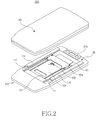
- a sliding module 100 for a portable terminal 200 (shown in FIG. 2 ) according to the present invention includes a sliding guide 102 mounted on a first housing 201 of the portable terminal 200 and a sliding plate 101 mounted on a second housing 202 of the portable terminal 200 and coupled to the sliding guide 102 while being able to slide.
- First guide grooves 121 and first guide rails 111 guide the second housing 202 so as to slide on the first housing 201.
- the sliding guide 102 includes a fixing plate 102a mounted on the first housing 201 and guide members 102b positioned on both sides of the fixing plate 102a.
- the fixing plate 102a is made of a metallic material
- the guide members 102b are made of a synthetic resin.
- the sliding guide 102 is preferably fabricated as a single unit in consideration of structural stability, reliability, and ease of manufacturing. In addition, use of a metallic material further improves the mechanical properties of the sliding guide 102, such as strength and resistance to wear.
- the sliding guide 102 has guide members 102b made of a synthetic resin and positioned on parts, which make direct contact with a component, particularly the sliding plate 101.
- the guide members 102b are made of a synthetic resin having resistance to fatigue, toughness, and resistance to wear, such as POM (polyoxymethylene).
- Each guide member 102b has a first guide groove 121 and a second guide rail 123, both of which extend in a longitudinal direction of the second housing 202.
- the first guide grooves 121 face the rear surface of the second housing 202.
- the second guide rails 123 extend parallel to the first guide grooves 121 and face the front surface of the first housing 201.
- the sliding plate 101 is mounted on the rear surface of the second housing 202 and is coupled to the sliding guide 102 so that it can slide while facing the sliding guide 102.
- the sliding plate 101 has at least one, preferably a pair of first guide rails 111 formed on a surface thereof.
- the first guide rails 111 protrude from a surface of the sliding plate 101 and extend in the sliding direction of the second housing 202.
- the first guide rails 111 engage with the first guide grooves 121 in such a manner that they can slide while being enclosed by the first guide grooves 121.
- the first guide grooves 121 and the first guide rails 111 guide the sliding movement of the second housing 202.
- at least the first guide rails 111 have a curved outer peripheral surface so that, even when any of them are out of manufacturing tolerance, the stability of sliding movement is ensured.
- Both the first guide grooves 121 and the first guide rails 111 extend in the sliding direction of the second housing 202 and limit any floating movement of the second housing 202 on its sliding plane so that the second housing 202 moves solely in the sliding direction.
- the sliding plate 101 has guide holders 115 and a coupling plate 104 mounted thereon, in order to guide the sliding movement of the second housing 202 and prevent it from escaping from the first housing 201.
- the guide holders 115 are mounted on both lateral ends of the sliding plate 101 so as to enclose both lateral ends of the sliding guide 102. Since the sliding guide 102 has the guide members 102b positioned on both sides of the fixing plate 102a, the guide holders 115 enclose the lateral ends of the guide members 102b of the sliding plate 101.
- Each guide holder 115 has a second guide groove 117 formed thereon so as to face a surface of the sliding plate 101.
- the second guide rails 123 of the guide members 102b engage with the corresponding second guide grooves 117 while being able to slide.
- the coupling plate 104 is mounted on a surface of the sliding plate 101 and is coupled to the sliding guide 102 so as to slide while facing it.
- the coupling plate 104 is positioned between the first guide rails 111.
- the coupling plate 104 has guide ribs 141 formed on both lateral ends thereof so as to slide while being interposed between the fixing plate 102a and the guide members 102b of the sliding guide 102.
- the sliding module 100 which is constructed as described above, slidably couples the second housing 202 to the first housing 201.
- the sliding module 100 has an elastic member 103 for implementing semi-automatic sliding operation of the second housing 202.
- a torsion spring is preferably used in the present invention.
- the torsion spring has a coil 131 and a pair of free ends 133 extending from both ends of the coil 131 in opposite directions.
- the torsion spring exerts elastic force in such a direction that the free ends 133 move away from each other.
- any type of elastic member may be used for the sliding module 100 according to the present invention, as long as it can exert elastic force in a direction moving both ends move away from each other.
- a compressed coil spring or a push rod incorporating a compressed coil spring may be used.
- One of the free ends 133 of the elastic member 103 is supported on the sliding guide 102 and the other is supported on the second housing 202, particularly on the coupling plate 104.
- the free ends 133 are closest to each other when the second housing 202 is positioned at a specific location within its sliding range.
- a driving force is generated in such a direction that the second housing 202 hides the first housing 201 and, when positioned on the other side of the specific location, the driving force is generated in such a direction that the second housing 202 exposes the first housing 201.
- the driving force is based on the action of the elastic member 103, as will be described in more detail with reference to FIGs. 4 to 6 .
- the sliding module 100 guides the movement of the second housing 202 in the Y direction while limiting its floating movement in the X and Z directions.
- the first and second guide rails 111 and 123 which extend in the Y direction, engage with the first and second guide grooves 121 and 117, respectively, which also extend in the Y direction, in order to limit the floating movement of the second housing 202 in the X direction.
- the first and second guide rails 111 and 123 have a curved outer peripheral surface
- the first and second guide grooves 121 and 117 have a curved inner peripheral surface
- the curved inner and outer peripheral surfaces cause the corresponding components to remain closely coupled to each other, even when a clearance occurs between them, such as clearance due to manufacturing tolerance, for example. This guarantees smooth sliding movement.
- the guide holders 115 and the coupling plate 104 are used to limit floating movement of the second housing 202 in the Z direction.
- the guide holders 115 are mounted on the sliding plate 101 in such a manner that both lateral ends of the sliding guide 101 (specifically, the lateral end of each guide member 102b) are interposed between the sliding plate 101 and the guide holders 115. This prevents the second housing 202 from escaping from the first housing 201 or floating in the Z direction.
- the second guide grooves 117 which are formed on the guide holders 115, engage with the second guide rails 123, which are formed on the guide members 102b, in order to guide the movement of the second housing 202 in the Y direction and limit its floating movement in the X direction.
- the guide ribs 141 of the coupling plate 104 are interposed between the fixing plate 102a and the guide members 102b of the sliding guide 102, in order to prevent the second housing 202 from escaping or floating in the Z direction.
- the coupling plate 104 solely prevents the second housing 202 from escaping or floating in the Z direction. Therefore, the coupling plate 104 may be omitted as long as the guide holders 115 alone can prevent the second housing 202 from escaping or floating in the Z direction.
- the sliding plate 101 In order to limit the range of sliding movement of the second housing 202, the sliding plate 101, particularly the first guide rails 111, have latching steps 113 and 119 formed on both ends thereof, respectively. When the second housing 202 slides, one of the latching steps 113 and 119 interferes with the sliding guide 102 and limits the range of sliding movement of the second housing 202.
- the sliding plate 101 of the sliding module 100 may be integrally formed on the second housing 202.
- the second housing 202 is fabricated in an injection process using a synthetic resin, as in the case of housings of conventional terminals 200, the first guide rails 111 and the latching steps 113 and 119 may be integrally formed on the rear surface of the second housing 202.
- the guide holders 115 and the coupling plate 104 are directly mounted on the rear surface of the second housing 202.
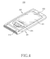
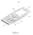
- FIGs. 4 through 6 show a series of steps for exposing the first housing 201 of the portable terminal 200 equipped with the sliding module 100 shown in FIG. 1 .
- the terminal 200 includes a first housing 201 typically containing a main board (not shown) and a second housing 202 provided with a display device 221, for example.
- a portion of the first housing 201 is exposed/hidden accordingly.
- the first housing 201 is provided with a transmitter unit 213 and a keypad 211, which is exposed/hidden by the sliding movement of the second housing 202.
- the second housing 202 has a functional keypad 225 and a receiver unit 223 positioned on both sides of the display device 221, respectively.
- a camera lens 219 (shown in FIG. 2 ) is positioned on a surface of the second housing 202, which is opposite the receiver unit 223, and is exposed/hidden by the sliding movement of the second housing 202.
- the sliding module 100 is not provided with the elastic member 103, the user must slide the second housing 202 manually when the user wants to expose or hide the keypad 211.
- the sliding module 100 is provided with the elastic member 103, the user has only to partially slide the second housing 202 in the range of sliding movement when the user wants to expose or hide the keypad 211.
- the keypad 211 is hidden by the second housing 202.
- the elastic member 103 exerts elastic force in such a direction that the free ends 133 move away from each other.
- the second housing 202 continuously hides the keypad 211.
- One of the latching steps 113 and 119 interferes with the sliding guide 102 and prevents the second housing 202 from moving any further.
- the user slides the second housing 202 in a direction to expose the keypad 211.
- the free ends 133 of the elastic member 103 gradually approach each other, and the elastic member 103 accumulates elastic force.
- the elastic force accumulated on the elastic member 103 begins to slide the second housing 202 in such a direction that the keypad 211 is hidden.
- the direction of the elastic force accumulated on the elastic member 103 varies after the second housing 202 passes a specific location wherein the free ends 133 are closest to each other. More particularly, when the second housing 202 is moved in such a direction that the keypad 211 is exposed, it approaches a specific location where the free ends 133 are closest to each other. After the second housing 202 passes that location, the elastic force from the elastic member 103 moves the second housing 202 in such a direction that the keypad 211 is exposed.
- the second housing 202 is said to be in a first region when it is positioned on one side of the specific location wherein the free ends 133 are closest to each other and when the elastic force acts in such a direction to hide the keypad 211.
- the second housing 202 is said to be in a second region when it is positioned on the other side of the specific location and when the elastic force acts in such a direction to expose the keypad 211.
- the elastic member 103 of the sliding module 100 exerts elastic force in such a direction that the keypad 211 is either exposed or hidden, based on the location of the second housing 202 in the sliding range.
- the elastic member 103 moves the second housing 202, when in the first region, in a direction to hide the keypad 211 and, when in the second region, in a direction to expose the keypad 211.
- the user only has to partially slide the second housing 202 when the user wants to expose or hide the keypad 211, because driving force is generated so as to fully move the second housing 202.
- the keypad 211 is completely exposed by the second housing 202.
- the elastic force from the elastic member 103 continuously acts on the second housing 202 in a direction to expose the keypad 211.
- the other latching step 113 of the sliding plate 101 interferes with the sliding guide 102 and prevents the second 202 from moving any further, as long as the keypad 211 is exposed.
- the sliding plate 101 of the sliding module 100 may be integral with the second housing 202, in order to reduce the number of components of the sliding module 100 and the manufacturing process, although the preferred embodiment of the present invention has been described with reference to a sliding plate 101, which is separate from the second housing 202, for the purpose of clarifying the construction of the sliding module 100.
- the sliding module for a portable terminal uses guide rails, guide grooves, and guide holders so as to smoothly guide the sliding movement of the second housing while limiting its floating movement in a direction different from the sliding direction.
- the sliding plate which carries the guide rails, etc., may be integral with a housing of the terminal, in order to reduce the number of components and the material cost, as well as simplify the manufacturing process, reducing manufacturing cost.
- the guide rails and the guide grooves have curved inner and outer peripheral surfaces, respectively, in order to prevent the housings of the terminal from vibrating due to manufacturing tolerance, for example, and to guarantee smooth sliding movement of the housings.
- the guide rails and the guide grooves engage each other in such a manner that the housings are stably coupled to each other while being able to slide smoothly.
Landscapes
- Engineering & Computer Science (AREA)
- Mechanical Engineering (AREA)
- Signal Processing (AREA)
- Telephone Set Structure (AREA)
- Casings For Electric Apparatus (AREA)
Claims (13)
- Terminal portable comprenant :un premier boîtier (201),un second boîtier (202) conçu pour coulisser sur le premier boîtier (201),un module de coulissement (100) raccordant, pour qu'il puisse coulisser, le second boîtier (202) au premier boîtier (201), le module de coulissement (100) comprenant :un guide de coulissement (102) monté sur le premier boîtier (201),une plaque coulissante (101) positionnée sur le second boîtier (202), accouplée avec une possibilité de coulissement au guide de coulissement (102) et lui faisant face,un premier rail de guidage (111) dépassant d'une surface de la plaque coulissante (101) et s'étendant dans la direction longitudinale,une première rainure de guidage (121) formée sur une surface du guide de coulissement (102) de façon à contenir le premier rail de guidage (111),un second rail de guidage (123) positionné sur le guide de coulissement (102) s'étendant en parallèle à la première rainure de guidage (121), etune seconde rainure de guidage (117) formée sur la plaque coulissante (101) de façon à contenir le second rail de guidage (123),dans lequel les premiers et seconds rails de guidage (111, 123) et les premières et secondes rainures de guidage (121, 117) sont disposés pour guider la plaque coulissante (101) afin de permettre à la plaque de coulissement d'effectuer des mouvements de coulissement sur le guide de coulissement (102).
- Terminal portable selon la revendication 1, dans lequel la plaque coulissante (101) est formée de manière intégrée sur le second boîtier (202).
- Terminal portable selon la revendication 1 ou 2, dans lequel les deux premiers rails de guidage (111) s'étendent parallèlement l'un à l'autre, et les deux rainures de guidage (121) sont adjacentes aux extrémités latérales respectives du guide de coulissement (102).
- Terminal portable selon l'une des revendications 1 à 3, dans lequel le premier rail de guidage (111) présente une surface périphérique extérieure courbe.
- Terminal portable selon l'une des revendications 1 à 4, dans lequel la plaque coulissante (101) comporte des dispositifs de soutien de guidage (115) montés sur chaque extrémité latérale respective, et les deux extrémités latérales du guide de coulissement (102) sont intercalées entre la plaque coulissante (101) et les dispositifs de soutien de guidage (115).
- Terminal portable selon la revendication 5, dans lequel la seconde rainure de guidage (117) est formée sur chaque dispositif respectif de soutien de guidage (115) et positionnée en faisant face à la plaque coulissante (101), et le second rail de guidage (123) est formé sur l'extrémité latérale du guide de coulissement (102) de façon à être enfermé par la seconde rainure de guidage (117).
- Terminal portable selon l'une des revendications 1 à 6, dans lequel les deux premiers et seconds rails de guidage (111, 123) s'étendent parallèlement les uns aux autres, et le module de coulissement (100) comprend en outre une plaque d'accouplement (104) montée sur une surface de la plaque coulissante (101) et positionnée entre la paire de premiers rails de guidage (111).
- Terminal portable selon l'une des revendications 1 à 7, dans lequel le guide de coulissement (102) comporte une plaque de fixation (102a) montée sur le premier boîtier (201) et des éléments de guidage (102b) fixés respectivement sur les deux côtés de la plaque de fixation (102a), et la première rainure de guidage (121) est formée sur chaque élément de guidage (102b).
- Terminal portable selon la revendication 8, dans lequel le module de coulissement (100) comprend en outre une plaque d'accouplement (104) montée sur la plaque coulissante (101), et les deux extrémités de la plaque d'accouplement (104) sont intercalées entre la plaque de fixation (102a) et les éléments de guidage (102b).
- Terminal portable selon l'une des revendications 1 à 9, comprenant en outre au moins un élément résilient (103) comportant un bobinage (131) ainsi qu'une paire d'extrémités libres s'étendant depuis les deux extrémités du bobinage (131) à distance l'une de l'autre, les extrémités libres étant respectivement supportées sur le guide de coulissement et la plaque coulissante (101).
- Terminal portable selon la revendication 10, dans lequel les extrémités libres sont les plus rapprochées l'une de l'autre lorsque la plaque coulissante (101) se trouve à un emplacement prédéterminé dans une plage de déplacement, et l'élément résilient (103) exerce une force élastique dans un sens écartant les extrémités libres l'une de l'autre.
- Terminal portable selon l'une des revendications 1 à 11, dans lequel des paliers d'encliquetage (113) sont formés sur les deux extrémités de la plaque coulissante (101) et, lorsque la plaque coulissante glisse, le guide de coulissement (102) vient interférer avec les paliers d'encliquetage (113) et limite la plage de déplacement de la plaque coulissante.
- Terminal portable selon l'une des revendications 1 à 12, dans lequel la première rainure de guidage (121) est formée sur une surface du guide de coulissement (102), et le second rail de guidage (123) est formé sur une surface différente du guide de coulissement (102).
Applications Claiming Priority (1)
| Application Number | Priority Date | Filing Date | Title |
|---|---|---|---|
| KR1020060003299A KR100678071B1 (ko) | 2006-01-11 | 2006-01-11 | 슬라이딩 모듈을 구비하는 휴대용 단말기 |
Publications (3)
| Publication Number | Publication Date |
|---|---|
| EP1809007A2 EP1809007A2 (fr) | 2007-07-18 |
| EP1809007A3 EP1809007A3 (fr) | 2007-12-05 |
| EP1809007B1 true EP1809007B1 (fr) | 2010-07-14 |
Family
ID=37944098
Family Applications (1)
| Application Number | Title | Priority Date | Filing Date |
|---|---|---|---|
| EP07100114A Ceased EP1809007B1 (fr) | 2006-01-11 | 2007-01-04 | Terminal portable comportant un module à glissière |
Country Status (5)
| Country | Link |
|---|---|
| US (1) | US20070161271A1 (fr) |
| EP (1) | EP1809007B1 (fr) |
| KR (1) | KR100678071B1 (fr) |
| CN (1) | CN101001269A (fr) |
| DE (1) | DE602007007674D1 (fr) |
Families Citing this family (10)
| Publication number | Priority date | Publication date | Assignee | Title |
|---|---|---|---|---|
| KR100865975B1 (ko) * | 2007-03-09 | 2008-10-29 | 정영조 | 휴대폰의 슬라이딩 개폐장치 |
| US8855728B2 (en) * | 2007-03-30 | 2014-10-07 | Nec Corporation | Mobile equipment and sliding structure therefor |
| JP5252381B2 (ja) * | 2007-03-30 | 2013-07-31 | 日本電気株式会社 | 携帯機器 |
| CN101420468B (zh) * | 2007-10-22 | 2011-12-28 | 宏达国际电子股份有限公司 | 电子装置 |
| US8121659B2 (en) * | 2007-12-20 | 2012-02-21 | Nokia Corporation | Slide mechanism |
| KR100891459B1 (ko) * | 2008-05-27 | 2009-04-01 | (주)쉘-라인 | 슬라이드형 개인휴대단말기 |
| CN102132455B (zh) * | 2009-02-09 | 2013-10-23 | 夏普株式会社 | 便携式无线装置 |
| CN101989449B (zh) * | 2009-08-07 | 2014-10-08 | 比亚迪股份有限公司 | 一种带有滑动组件的便携式终端 |
| JP5733308B2 (ja) * | 2010-05-20 | 2015-06-10 | 日本電気株式会社 | 携帯機器 |
| CN109005270A (zh) * | 2018-10-30 | 2018-12-14 | Oppo(重庆)智能科技有限公司 | 移动终端 |
Family Cites Families (8)
| Publication number | Priority date | Publication date | Assignee | Title |
|---|---|---|---|---|
| US5973947A (en) * | 1999-02-04 | 1999-10-26 | Shin Jiuh Corp. | Power supplying apparatus with multiple power-supplying units |
| TW408868U (en) * | 1999-04-23 | 2000-10-11 | Liau Sheng Shing | Flip cover type connector |
| JP3456928B2 (ja) * | 1999-10-18 | 2003-10-14 | Smc株式会社 | 電磁弁集合体の給電装置 |
| KR100484732B1 (ko) * | 2002-11-19 | 2005-04-22 | 삼성전자주식회사 | 슬라이딩 타입 휴대용 무선 단말기 |
| KR100587773B1 (ko) * | 2003-10-30 | 2006-06-09 | (주)쉘-라인 | 곡면 슬라이드 폰 |
| KR100617690B1 (ko) * | 2003-11-10 | 2006-08-28 | 삼성전자주식회사 | 슬라이딩 타입 휴대용 무선 단말기 |
| JP2005210649A (ja) * | 2004-01-26 | 2005-08-04 | Kato Electrical Mach Co Ltd | 携帯端末のスライド機構 |
| US6942153B1 (en) * | 2004-05-25 | 2005-09-13 | Unitech Electronics Co.,Inc. | Handheld computer |
-
2006
- 2006-01-11 KR KR1020060003299A patent/KR100678071B1/ko not_active Expired - Fee Related
- 2006-11-15 US US11/599,803 patent/US20070161271A1/en not_active Abandoned
- 2006-12-20 CN CNA2006101686451A patent/CN101001269A/zh active Pending
-
2007
- 2007-01-04 EP EP07100114A patent/EP1809007B1/fr not_active Ceased
- 2007-01-04 DE DE602007007674T patent/DE602007007674D1/de active Active
Also Published As
| Publication number | Publication date |
|---|---|
| US20070161271A1 (en) | 2007-07-12 |
| DE602007007674D1 (de) | 2010-08-26 |
| KR100678071B1 (ko) | 2007-02-02 |
| CN101001269A (zh) | 2007-07-18 |
| EP1809007A3 (fr) | 2007-12-05 |
| EP1809007A2 (fr) | 2007-07-18 |
Similar Documents
| Publication | Publication Date | Title |
|---|---|---|
| US7184806B2 (en) | Sliding module for mobile terminal | |
| EP1648145B1 (fr) | Module de coulissement pour un terminal portable du type coulissant | |
| CN100512334C (zh) | 滑动式便携式无线终端 | |
| US8634884B2 (en) | Sliding-type portable terminal | |
| US7953464B2 (en) | Sliding-type portable terminal | |
| EP1703705B1 (fr) | Module coulissant pour un terminal de communication portable | |
| EP1809007B1 (fr) | Terminal portable comportant un module à glissière | |
| EP1783983B1 (fr) | Module coulissant pour un terminal mobile | |
| EP1786181A2 (fr) | Téléphone portable comportant un module coulissant pour faire glisser des boîtiers dans deux directions différentes | |
| US8478367B2 (en) | Portable terminal having sliding module | |
| EP1662754B1 (fr) | Module coulissant pour un terminal de communication portable de type coulissant | |
| KR101409510B1 (ko) | 슬라이딩형 휴대용 단말기 | |
| EP1734725B1 (fr) | Terminal portable avec module de coulissement | |
| KR20080095070A (ko) | 슬라이드형 개인휴대단말기 | |
| KR100629241B1 (ko) | 슬라이드형 개인휴대단말기 | |
| KR100713375B1 (ko) | 휴대용 단말기의 슬라이딩 모듈 | |
| KR200411625Y1 (ko) | 휴대폰용 슬라이드 힌지 모듈 | |
| KR100778281B1 (ko) | 슬라이드형 개인휴대단말기 | |
| KR100678037B1 (ko) | 휴대용 단말기의 슬라이딩 모듈 | |
| KR101138068B1 (ko) | 슬라이딩 모듈을 구비하는 휴대용 단말기 | |
| KR100678061B1 (ko) | 슬라이딩 모듈을 구비하는 휴대용 단말기 | |
| KR100800661B1 (ko) | 휴대용 단말기의 슬라이딩 모듈 | |
| KR20060047119A (ko) | 슬라이딩 타입 휴대용 단말기의 슬라이딩 모듈 | |
| KR20080006728A (ko) | 슬라이딩 타입 휴대용 단말기 |
Legal Events
| Date | Code | Title | Description |
|---|---|---|---|
| PUAI | Public reference made under article 153(3) epc to a published international application that has entered the european phase |
Free format text: ORIGINAL CODE: 0009012 |
|
| 17P | Request for examination filed |
Effective date: 20070104 |
|
| AK | Designated contracting states |
Kind code of ref document: A2 Designated state(s): AT BE BG CH CY CZ DE DK EE ES FI FR GB GR HU IE IS IT LI LT LU LV MC NL PL PT RO SE SI SK TR |
|
| AX | Request for extension of the european patent |
Extension state: AL BA HR MK YU |
|
| PUAL | Search report despatched |
Free format text: ORIGINAL CODE: 0009013 |
|
| AK | Designated contracting states |
Kind code of ref document: A3 Designated state(s): AT BE BG CH CY CZ DE DK EE ES FI FR GB GR HU IE IS IT LI LT LU LV MC NL PL PT RO SE SI SK TR |
|
| AX | Request for extension of the european patent |
Extension state: AL BA HR MK YU |
|
| 17Q | First examination report despatched |
Effective date: 20080228 |
|
| AKX | Designation fees paid |
Designated state(s): DE FR GB |
|
| GRAP | Despatch of communication of intention to grant a patent |
Free format text: ORIGINAL CODE: EPIDOSNIGR1 |
|
| GRAS | Grant fee paid |
Free format text: ORIGINAL CODE: EPIDOSNIGR3 |
|
| GRAA | (expected) grant |
Free format text: ORIGINAL CODE: 0009210 |
|
| AK | Designated contracting states |
Kind code of ref document: B1 Designated state(s): DE FR GB |
|
| REG | Reference to a national code |
Ref country code: GB Ref legal event code: FG4D |
|
| REF | Corresponds to: |
Ref document number: 602007007674 Country of ref document: DE Date of ref document: 20100826 Kind code of ref document: P |
|
| PLBE | No opposition filed within time limit |
Free format text: ORIGINAL CODE: 0009261 |
|
| STAA | Information on the status of an ep patent application or granted ep patent |
Free format text: STATUS: NO OPPOSITION FILED WITHIN TIME LIMIT |
|
| 26N | No opposition filed |
Effective date: 20110415 |
|
| REG | Reference to a national code |
Ref country code: DE Ref legal event code: R097 Ref document number: 602007007674 Country of ref document: DE Effective date: 20110415 |
|
| REG | Reference to a national code |
Ref country code: FR Ref legal event code: PLFP Year of fee payment: 10 |
|
| REG | Reference to a national code |
Ref country code: FR Ref legal event code: PLFP Year of fee payment: 11 |
|
| REG | Reference to a national code |
Ref country code: FR Ref legal event code: PLFP Year of fee payment: 12 |
|
| PGFP | Annual fee paid to national office [announced via postgrant information from national office to epo] |
Ref country code: FR Payment date: 20191223 Year of fee payment: 14 |
|
| PGFP | Annual fee paid to national office [announced via postgrant information from national office to epo] |
Ref country code: GB Payment date: 20191223 Year of fee payment: 14 Ref country code: DE Payment date: 20191220 Year of fee payment: 14 |
|
| REG | Reference to a national code |
Ref country code: DE Ref legal event code: R119 Ref document number: 602007007674 Country of ref document: DE |
|
| GBPC | Gb: european patent ceased through non-payment of renewal fee |
Effective date: 20210104 |
|
| PG25 | Lapsed in a contracting state [announced via postgrant information from national office to epo] |
Ref country code: FR Free format text: LAPSE BECAUSE OF NON-PAYMENT OF DUE FEES Effective date: 20210131 |
|
| PG25 | Lapsed in a contracting state [announced via postgrant information from national office to epo] |
Ref country code: GB Free format text: LAPSE BECAUSE OF NON-PAYMENT OF DUE FEES Effective date: 20210104 Ref country code: DE Free format text: LAPSE BECAUSE OF NON-PAYMENT OF DUE FEES Effective date: 20210803 |