EP1786236B1 - Paarweise komplementärer Entzerrer - Google Patents
Paarweise komplementärer Entzerrer Download PDFInfo
- Publication number
- EP1786236B1 EP1786236B1 EP05024416A EP05024416A EP1786236B1 EP 1786236 B1 EP1786236 B1 EP 1786236B1 EP 05024416 A EP05024416 A EP 05024416A EP 05024416 A EP05024416 A EP 05024416A EP 1786236 B1 EP1786236 B1 EP 1786236B1
- Authority
- EP
- European Patent Office
- Prior art keywords
- signal
- signals
- frequency
- level
- processors
- Prior art date
- Legal status (The legal status is an assumption and is not a legal conclusion. Google has not performed a legal analysis and makes no representation as to the accuracy of the status listed.)
- Expired - Lifetime
Links
Images


Classifications
-
- H—ELECTRICITY
- H03—ELECTRONIC CIRCUITRY
- H03G—CONTROL OF AMPLIFICATION
- H03G5/00—Tone control or bandwidth control in amplifiers
- H03G5/02—Manually-operated control
- H03G5/025—Equalizers; Volume or gain control in limited frequency bands
Definitions
- the present invention deals with the field of signal modification.
- it deals with a method and device/s for the selection of frequency portions of at least two versions of a signal which are summed to create a signal which may be superior to, and/or avoid problems found in,one or more of the source signals.
- Loudspeaker systems are made of separate speaker elements, such as woofers (low frequency drivers), tweeters (high frequency drivers), and midrange drivers. Each element is optimized for a specific and limited frequency band, and requires the absence of frequencies not in its limited frequency band.
- a common speaker crossover divides an incoming signal into 2 or more frequency bands for distribution to separate speaker elements.
- filters/equalizers/etc. are constructed to include a second signal path, whose frequency response is essentially the inverse of the original signal path.
- This second signal path is coupled with a second source of the signal, which is chosen only for its quality in the frequency band/s reduced in the first signal path.
- the first filtered signal and second 'inverse-filtered' signal are then summed, which may result in a signal similar in accuracy to the first signal path alone, and may also have an increase in the rejection of the undesired signal.
- the two source signals are assumed to be of similar intensity within the pertinent frequency band/s, though compensation can likely be made when they are not.
- a second signal may be supplied by a second microphone placed far from the offending steam sound. This may be in an odd corner of the room, which may not be good for the overall sound of the music - this second spot needs only to have an increase in ratio of desired sound (music) to undesired sound (steam hiss) in the frequency range of the undesired sound, as compared to the first signal in the same frequency range.
- the apparatus is adjusted to decrease the energy of the original signal's offending frequency band, where the amount of unwanted noise is high, it simultaneously increases the energy in the same band of the second signal, where the amount of unwanted noise is low.
- the summing of the signals will provide an increase in the reduction of the unwanted noise, while maintaining the fidelity of the original music.
- FIG. 1 is a general block diagram of a typical audio equalizer as is known in the art. The type shown here is for a single channel of a fully-parametric equalizer.
- An input signal 11 is fed to a filter circuit 12 whose parameters are determined by the controls 'f', 'Q' and 'g' 13.
- Control 'f' determines the center frequency of the affected area.
- Control 'Q' determines the bandwidth of the affected area.
- Control 'g' reduces (by convention, counterclockwise from center position) or increases (clockwise from center position) the signal in the area determined by the settings of 'f' and 'Q'. At the center setting of 'g', where there is no increase or decrease of signal, the settings of 'f' and 'Q' have no effect.
- the final signal may be sent to an output device 14.
- input signal 11 and filter circuit 12 it is helpful to refer to input signal 11 and filter circuit 12 as the PRIMARY input signal and filter circuit.
- the first category is that of the simple filter shapes known as highpass, lowpass, bandpass, and notch(i.e., band reject). When these are added to the original signal, an eq (equalizer) type filter is created.
- FIG. 2A is a general block diagram of an audio equalizer arranged for the addition of a complementary pair of inverse filter elements, according to an embodiment of the present invention.
- both filter elements 12 and 22 may be of the eq type.
- a second input signal 21 is fed to a second filter circuit 22, which may be identical to filter circuit 12.
- Both filter circuits, 12 and 22, are controlled by the same single set of controls 13.
- the 'g' control's effect on the secondary circuit 22 may be the opposite of its effect on the primary circuit 12.
- the outputs are mixed by circuit 23, which may provide control (not shown) of the relative strength of outputs 12 and 22, if desired. Due to the nature of some signals, phase inversion switches may be desireable at suitable locations for any embodiment of the present invention.
- the boost gain should complement the cut gain in a proportion that maintains the overall gain relationship on the outputs of 12 and 22 when combined.
- the band gain is 0 dB for both channels 12 and 22, and the sum of their outputs yields a gain of +6 dB, assuming similar in-phase signals.
- channel 12's frequency band is reduced to minus infinity dB
- channel 22's frequency band is boosted to +6 dB to compensate for the reduction.
- channel 12 is boosted +6 dB
- channel 22 is reduced to minus infinity dB.
- Another embodiment similar to the device described above, configures primary channel 12 as eq with reduction filtering only, and configures secondary channel 22 as pass-band filtering with no flat setting.
- gain control 'g' set to full gain (full clockwise) at primary channel 12
- response is flat 0 dB gain for filter 12 and minus infinity dB for the entire bandwidth of filter 22.
- the output of mixer 23 is therefore the unaltered primary channel input 11 from channel 12, rather than the sum of channels 12 and 22 as above.
- the corresponding frequencies of 22 are increased to "fill the holes" made by the activity of 12.
- the corresponding frequencies of 22 are at unity gain.
- Filter channels 12 and 22 may have an input gain trim to adjust levels to compensate for differences in the input signals 11 and 21.
- the channel filters may have a switch to toggle function between these two arrangements.
- Step 2 involves first INCREASING the level of the offending sound because it is easier for a human operator to isolate a problem area by hearing it at a loud level, then reducing it as indicated in Step 3.
- FIG. 9 shows a schematic diagram of an implementation of a single band complementary pair equalizer which makes special use of signal phase relationships to accomplish both the primary signal band-reject (notch) filter and the secondary signal bandpass filter to be accomplished by a single circuit.
- Amplifier AR3 inverts secondary signal 21 and mixes it with in-phase primary signal 11. This mixed signal is fed through a bandpass filter (C7,C8,R11,R12, etc.) which is inverted by the inverting input of amplifier AR2. The resultant signal at this point is the selected passband region of the inverted phase primary signal 11 and the in-phase secondary signal 21. To this mixed signal is added the original in-phase primary signal, via R4.
- the portion of the mixed bandpass signal which is the inverted phase region of the primary signal, cancels with the complementary portion of the in-phase complete primary signal and results in a band-reject (notch) filter for the primary signal.
- the portion of the mixed bandpass filter output signal that is the in-phase region of the secondary signal remains unaffected.
- the single bandpass circuit (C7,C8,R11,R12, etc.) suffices to perform a band-reject function on primary signal 11 and a bandpass function on secondary signal 21.
- This implementation is only one of many possible ways to accomplish the task. Another possibility is to simply combine the primary and secondary signals, pass the combined signal through the bandpass filter, and add to the filter's output the primary signal unfiltered, but 180 degrees out of phase. It is important to get the phase relationships correct, making sure that the primary bandpassed signal is added to the original primary signal, these two bearing a 180 degree phase relationship to each other.
- FIG. 2B is identical to FIG. 2A , except for the addition of a 2nd set of controls 24 which affect only Secondary Channel EQ 22. Because of the complexity of some signals, the imperfection of any physical embodiments, etc., it may be advantageous to provide this set to allow the parameters of the secondary path's filters to be varied from the positions set by the primary controls 13 (widen or narrow the Q, sweep the frequency up/down, increase/reduce the gain). Operation is as described as for FIG. 2A , but would add a step at the end for fine tuning with the controls 24.
- the device may be constructed with multiple bands (sections), each section operating in the same way.
- Prior art audio equalizers currently used for the purposes of the example above generally contain 3, 4 or 5 bands. Care must be given to the arrangement of the filter elements (re:parallel,series,etc.) so that each complementary primary/secondary pair achieves the desired result. This phenomenum is known in the art, and is dependent on the type of filter element used.
- the first category is that of the simple filter shapes known as highpass, lowpass, bandpass, and notch (i.e., band reject). These may be mathematically represented by T(s) , where s is the complex frequency and T(s) is the voltage transfer function of the complex frequency. When these are added to the original signal, an eq (equalizer) type filter is created. An equalizer can be crudely represented by (1 - T(s)) , and its complement would be (1 + T(s)) . For audio purposes in general, a group of simple filters usually works best arranged in parallel (where transfer functions are added), and a group of eq type filters works best arranged in series (where transfer functions are multiplied).
- FIG. 3A is a general block diagram of a typical prior art multi-band audio equalizer, similar to FIG. 1 , but with multiple eq type bands/sections (each of which may be identical, or with different or overlapping frequency ranges). These are connected in series, which produces the desired effect for these devices.
- the gain of each band's transfer function T may vary from above 0 to below 0, allowing both boost and cut.
- FIG. 3B shows this scenario adapted for the addition of inverse filter elements, according to an embodiment of the present invention, where the secondary channel elements are eq type filters.
- This error increases for each additional band. If all filters T1(s)...TN(s) are narrow bandpass filters with significantly different pole frequencies, the error can be kept to within ⁇ 2 dB across the spectrum.
- the error created by this series arrangement may be tolerable if independence of the inputs is to be maintained. Maintaining independence is useful in many circumstances, such as when manipulating a stereo pair.
- the separate set of controls 24 shown in FIG. 2B allowing individual adjustments to the secondary channel parameters for each band, allow an operator to compensate for this error.
- the system may be configured as a graphic equalizer with fixed frequency and Q for each band, only varying the gains. A scenario such as this can be arranged to limit the multi-band error to a small tolerance.
- FIG. 3C shows an arrangement which reduces or eliminates this error.
- the gain of each band's transfer function T may vary from -1 to +1, allowing both boost and cut, but all elements of secondary channel 22 must be of the simple filter type.
- FIG. 3B Also changed here from FIG. 3B are the inputs and outputs of each band of secondary channel 22.
- Each band's secondary element receives its input directly from secondary input signal 21, and the output of each band's secondary element is supplied to the input of the next band's PRIMARY element.
- the output transfer function is In A ⁇ 1 - T ⁇ 1 s + In B ⁇ T ⁇ 1 s ⁇ 1 - T ⁇ 2 s + In B ⁇ T ⁇ 2 s ... ⁇ ... 1 - TN s + In B ⁇ TN s + In B With both inputs equal to V in , the expression can be factored as: V in ⁇ [ [ 1 - T ⁇ 1 s ) + T ⁇ 1 s ] ⁇ 1 - T ⁇ 2 s + T ⁇ 2 s ... ⁇ ... 1 - TN s + TN s + 1 ] which reduces to 2V in .
- the addition of secondary channel input 21 to the final output, shown as line 35, is required for the simple filter elements of secondary channel 22 to operate with both boost and cut.
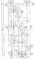
- FIG. 3D is a general block diagram of an arrangement which avoids this error for a primary/secondary pair of channels with a multiplicity of bands 12/22 and a multiplicity of secondary inputs 21 (any or all of the secondary inputs 21 may be from a single source). All elements of secondary channel 22 should be of the simple filter type. The gain of each band's transfer function T may vary only from 0 to +1, allowing only cut in the primary channel filters. As in FIG. 3C , the filter functions are here incorporated at each step. There are no errors in maintaining gain relationships when all the inputs of 11 and 21 are equal, other than errors of construction tolerances.
- a filter is represented by T(s) , and an equalizer by (1 - T(s)).
- the final transfer function of the device is as follows: In A ⁇ 1 - T ⁇ 1 s + In 1 ⁇ T ⁇ 1 s ⁇ 1 - T ⁇ 2 s + In 2 ⁇ T ⁇ 2 s ... ⁇ ... 1 - TN s + In N ⁇ TN s
- V in ⁇ 1 - T ⁇ 1 s the expression can be factored as: V in ⁇ 1 - T ⁇ 1 s ) + T ⁇ 1 s ⁇ 1 - T ⁇ 2 s + T ⁇ 2 s ... ⁇ ... 1 - TN s + TN s which equals V in .
- the meaning of this equivalency is that there is a direct replacement of frequencies from one channel to another.
- each secondary channel filter section of FIG. 3D may be summed separately to maintain channel independence, although accuracy is compromised. If all filters T1(s) ⁇ TN(s) are narrow bandpass filters with significantly different pole frequencies, the error can be kept to within ⁇ 2 dB across the spectrum.
- the separate set of controls 24 shown in FIG. 2B allowing individual adjustments to the secondary channel parameters for each band, allow an operator to compensate for this error.
- FIG. 3B and 3C are most appropriate where 2 useful signals are present, and one wants to affect certain frequency ranges of these two complementarily (boost one and cut the other).
- the embodiments of FIG. 3D are most appropriate when one wants to cut problematic frequency ranges of an otherwise useful signal, and 'fill them in' (replace them) with useful sections of an otherwise undesireable signal.
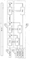
- FIG. 4 is a general block diagram of an embodiment with a switching arrangement which allows a user to choose one of the embodiments of FIGS. 3A, 3B , 3C , and 3D from within a single device. Since the switching process is a straightforward implementation of the elements discussed above, a detailed descripton is not necessary here. Switch elements labeled the same (e.g., all switches marked F1) operate as a unit, and are toggled by a single user selection. The switching process must enable certain gain adjustments for proper operation.
- a microphone underneath the drum receives a disproportionate amount of this high frequency signal, compared to the normal sound of the drum.
- This filtered signal from a microphone below the drum is missing the problematic hi-hat crosstalk, but also has little of the drum's low frequencies - what remains is a good, but overly strong, representation of the drum's higher frequency range.
- the gain of microphone pre-amp AR2 (used for the microphone below the drum) is set to track about -9 dB lower than the the gain for pre-amp AR1 (used for the microphone above the drum).
- This assumes the use of microphones with equivalent sensitivity and signal level, each of the 2 microphones being placed about 1 inch from its appropriate drumhead.
- the resulting combined output sounds most similar to the acoustic sound when mixed at a majority of frequency settings determined by the dual potentiometer R8 + R10.
- the user can vary the level of bottom microphone 21's signal independently with variable resistor R2 to account for differences in microphones, snare timbre, placement, and taste.
- a single gain control, dual potentiometer R3 + R6, varies the pre-amp gain applied to both signals 11 (above drum microphone) and 21 (below drum microphone) in tandem. This maintains the set gain ratio, which allows the user to adjust level without worrying about the balance of the microphone signals.
- the filter circuit 52 of FIG. 5 acts as a variable-frequency low pass for input signal 11 (from the microphone above the drum) and as a variable-frequency high pass for input signal 21 (from the microphone below the drum).
- the pole frequency for the low pass overlaps the pole frequency for the high pass by approximately one octave. Both poles are adjusted simultaneously with the single control (R8 + R10). As the pole frequencies are lowered, the overlap of the frequency poles drops to less than a third of an octave.
- the high pass responds as a first-order filter in parallel with a second-order filter.
- the low pass filter is comprised of two first-order filters in series, with resonance.
- Connection 51 can be to a) signal 11's pre-amp output, b) ground, or c) filter circuit 52's output, each yielding.a slightly different frequency response at the crossover frequencies. Scenarios a) and b) differ only in the top mic's resonance response, whereas c) adds resonance to both filter functions. Our experimentation shows that the approximate useful low-pass frequency range is 160 Hz to 8 kHz, and the approximate useful high-pass frequency range is 125 Hz to 4 kHz.
- FIG. 6 is simplified filter section versions of the example of FIG 5 , where a cost savings can be attained in circumstances that will allow for it.
- input signal 11's low-pass frequency pole and filter slope vary as in FIG. 5 , but the filter pole for the input signal 21 (from the microphone below the drum) is fixed at about 1 kHz.
- FIG. 7 is an even simpler version, with poles for both the low-pass and high-pass filters fixed at about 1kHz. They are shown here as first-order filter functions, but other filter orders can be easily constructed.
- FIG. 8 shows an embodiment for another use of the present invention, as a variable emphasis/de-emphasis noise-reduction device.
- Primary Channel 12 adds emphasis by boosting a region
- Secondary Channel 22 de-emphasizes by cutting the same region.
- the gain relationships should be maintained not when summed, (i.e., mixed in parallel) but rather when multiplied (i.e., used in series); therefore output device 14 is inserted between 12 and 22 - the output of 14 becomes the Input Signal 21.
- the total transfer function of 12 must be the reciprocal of the total transfer function of 22. The result is transparent for any linear function of processing implemented in the device/s 14. Since multiplication is associative, a multiplicity of bands can be used in series without any errors described in previous designs. Note that since the reciprocal of infinite cut is infinite boost, infinite cut is not possible.
- Another specific application is for use with any acoustical instrument, such as the guitar.
- the guitar is commonly used with three common transducer types: air pressure microphones, accelerometer (physical vibration induction) pickups, and magnetic induction pickups.
- air pressure microphones For truest fidelity, the microphone is placed at least as far from the instrument as the largest sound producing dimension of the instrument; for a guitar, this distance is between 0.5 and 1.0 meters.
- An accelerometer pickup induces energy from the physical vibrations of a particular part of the guitar's material body, usually the wood near the bridge (the energy from the strings is transmitted through the bridge to the rest of the instrument, so the vibrations are strongest there).
- the vibrations so induced are somewhat like the air-born sound waves which we normally hear, and the result, if done carefully, is a mediocre but recognizable instrument sound.
- These pickups do not suffer from isolation and feedback problems nearly as much as air pressure microphones.
- a magnetic induction pickup requires the instrument to have metal strings, necessary to create the magnetic field which is then induced.
- the instrument is not required to (and most commonly does not) produce enough acoustic energy to be heard without the amplification for which it was designed, though it arose out of attempts to amplify pre-existing acoustic instruments.
- the sound produced only remotely resembles that produced by an instrument's body, but has given rise to what are essentially new instruments, such as the electric guitar, electric bass, and electric violin.
- Acoustic guitars provide enough acoustic energy to be heard without assistance, but the amount of energy is small, and limits un-amplified use to a small range of circumstances.
- amplification is generally needed.
- the system source the microphone or other transducer
- a positive feedback loop is often created that drives the speaker amplifier into saturation, producing a loud howl. This is a common occurrence.
- the feedback generally occurs at specific frequency regions that are emphasized by accidental (random) circumstances of instrument construction, room construction, and placement of the instrument and transducer within the room and with relation to the amplification system.
- Air pressure devices are more sensitive to this problem than the other, lower fidelity induction devices.
- the common prior art corrective is to use a device such as an equalizer 12 ( FIGS. 1 , 3A ) to reduce the level of the signal in the problematic frequency bands. This lowers the fidelity of the reduced signal, and a compromise must be reached.
- a complimentary-pair equalizer may greatly improve the quality of sound in this circumstance.
- a high-fidelity (e.g., air pressure microphone) signal is used as Primary Input Signal 11
- a lower fidelity (e.g., accelerometer 'pickup') signal is used as Secondary Input Signal 21.
- An appropriate embodiment may be used, such as one of those in the FIGS. 2A, 2B , 3B , 3C , or 3D .
- frequency bands which include feedback in the acoustic microphone are merely reduced.
- the present invention not only reduces these bands from the (primary) acoustic microphone signal, but replaces them with the (secondary) accelerometer signal from the same bands. This may provide a higher fidelity overall signal quality than that from the accelerometer alone, and may also greatly increase the gain-before-feedback level available with only an air pressure microphone.
Landscapes
- Tone Control, Compression And Expansion, Limiting Amplitude (AREA)
- Addition Polymer Or Copolymer, Post-Treatments, Or Chemical Modifications (AREA)
- Filters And Equalizers (AREA)
Claims (34)
- Verfahren zur Verarbeitung von Signalen mit:Bereitstellen eines ersten Signals (11) und eines zweiten Signals (21), wobei das erste Signal (11) und zweite Signal (21) durch einen ersten und einen zweiten Wandler zugeführt werden, die ein erstes und zweites Signal (11, 21) produzieren, die durch eine Quelle über unterschiedliche Positionen der Wandler relativ zur Quelle oder über die Fortleitung unterschiedlicher Energiemedienarten erzeugt werden, wobei das erste und zweite Signal (11, 21) jeweils ein Frequenzspektrum mit mehreren Frequenzbändern so aufweisen, daß das zweite Signal (21) eine Zunahme des Verhältnisses eines erwünschten Klangs zu einem unerwünschten Klang in einem Frequenzbereich verglichen mit dem ersten Signal (11) im gleichen Frequenzbereich hat;Zuführen des ersten und zweiten Signals (11, 21) zu einem ersten bzw. einem zweiten Signalprozessor (12, 22);Auswählen mindestens eines der mehreren Frequenzbänder, das den unerwünschten Klang aufweist, mit dem ersten Signalprozessor (12) und Auswählen mindestens eines der mehreren Frequenzbänder mit dem zweiten Signalprozessor (22), wobei die Auswahlen kleiner als das Frequenzspektrum der mehreren Frequenzbänder für das erste und zweite Signal sind;Einstellen eines Pegels für das durch den ersten Prozessor (12) ausgewählte mindestens eine Frequenzband mit dem ersten Prozessor und Einstellen eines Pegels für das durch den zweiten Prozessor (22) ausgewählte mindestens eine Frequenzband mit dem zweiten Prozessor, so daß eine Pegelzunahme des ausgewählten mindestens einen Frequenzbands in dem ersten oder zweiten Signal zu einer Pegelabnahme des ausgewählten mindestens einen Frequenzbands in dem anderen aus dem ersten und zweiten Signal führt und die Pegelzunahme sowie die resultierende Pegelabnahme unabhängig von Änderungen an anderen Frequenzbändern im ersten und zweiten Signalprozessor durchgeführt werden; undSummieren (23) des eingestellten und der anderen Frequenzbänder des ersten Signals (11) sowie des eingestellten und der anderen Frequenzbänder des zweiten Signals (21).
- Verfahren nach Anspruch 1, wobei eine Größe der Pegelzunahme gleich einer Größe der Pegelabnahme ist.
- Verfahren nach Anspruch 1 oder 2, ferner mit:Einstellen des Pegels des ersten und zweiten Signals vor Zuführen des ersten und zweiten Signals zu den Signal-(11, 21) Prozessoren.
- Verfahren nach Anspruch 1, 2 oder 3, ferner mit:getrenntes Einstellen der ausgewählten Frequenzbänder für das erste und zweite Signal (11, 21).
- Verfahren nach einem der Ansprüche 1 bis 4, wobei das erste und zweite Signal (11, 21) einer ersten und einer zweiten Gruppe von Signalprozessoren zugeführt werden und der Einstellschritt mit der ersten und zweiten Gruppe von Signalprozessoren vorgenommen wird.
- Verfahren nach Anspruch 5, wobei im Zufuhrschritt die erste Gruppe von Signalprozessoren in Reihe gekoppelt ist und die zweite Gruppe von Signalprozessoren parallel gekoppelt ist und im Kombinierschritt entsprechende Ausgaben von Signalprozessoren aus der ersten und zweiten Gruppe von Prozessoren individuell summiert werden.
- Verfahren nach Anspruch 6, wobei im Kombinierschritt ein unverändertes alternatives Signal mit dem ersten und alternativen Signal nach dem Einstellschritt kombiniert wird.
- Verfahren nach einem der Ansprüche 1 bis 7, wobei das erste und zweite Signal (11, 21) von einer ersten bzw. einer zweiten Position relativ zu einem Instrument abgeleitet werden.
- Verfahren nach Anspruch 8, wobei das Instrument eine kleine Trommel ist und die erste Stelle über der kleinen Trommel und die zweite Stelle unter der kleinen Trommel liegt.
- Verfahren nach Anspruch 9, wobei im Einstellschritt ein voreingestelltes Verhältnis einer Verstärkung für das zweite Signal (21) zwischen 11 und 5 dB niedriger als die Verstärkung für das erste Signal (11) ist.
- Verfahren nach Anspruch 8, wobei der erste oder der zweite Signalprozessor ein Hochpaßfilter und der andere aus dem ersten und zweiten Signalprozessor ein Tiefpaßfilter ist.
- Verfahren nach Anspruch 11, wobei ein Pol für jedes der Filter auf 1 kHz eingestellt ist.
- Verfahren nach Anspruch 11, wobei ein Pol des Hochpaßfilters auf 1 kHz eingestellt ist und ein Pol des Tiefpaßfilters zwischen einem Tiefpaß erster Ordnung mit etwa 160 Hz und einem Tiefpaß zweiter Ordnung mit etwa 8 kHz variabel ist.
- Verfahren nach Anspruch 11, ferner mit:Einstellen eines Pols für das jeweilige Hochpaß- und Tiefpaßfilter.
- Verfahren nach Anspruch 11, wobei sich an Hochfrequenzpolen das Hochpaß- und Tiefpaßfilter etwa eine Oktave überschneiden und sich an Niederfrequenzpolen das Hochpaß- und Tiefpaßfilter etwa ein Drittel einer Oktave überschneiden.
- Verfahren nach Anspruch 14, wobei ein annähernder Einstellbereich des Frequenzpols des Hochpaßfilters zwischen 160 Hz und 8 kHz in Verbindung mit einem annähernden Einstellbereich des Tiefpaßfilters liegt, der zwischen 125 Hz bis 4 kHz liegt.
- Vorrichtung zur Verarbeitung von Signalen mit:einem ersten Eingang, um ein erstes Signal (11) zu empfangen, und einem zweiten Eingang, um ein zweites Signal (21) zu empfangen, wobei das erste Signal (11) und zweite Signal (21) durch einen ersten und einen zweiten Wandler zugeführt werden, durch eine Quelle über unterschiedliche Positionen der Wandler relativ zur Quelle erzeugt werden, wobei das erste und zweite Signal jeweils ein Frequenzspektrum mit mehreren Frequenzbändern so aufweisen, daß das zweite Signal (21) eine Zunahme des Verhältnisses eines erwünschten Klangs zu einem unerwünschten Klang in einem Frequenzbereich verglichen mit dem ersten Signal (11) im gleichen Frequenzbereich hat;einem ersten und einem zweiten Signalprozessor (12, 22), die ausgebildet sind, das erste bzw. zweite Signal zu empfangen;wobei der erste Signalprozessor (12) ferner ausgebildet ist, mindestens eines der mehreren Frequenzbänder mit dem unerwünschten Klang auszuwählen, wobei die Auswahl kleiner als das Frequenzspektrum der mehreren Frequenzbänder für das erste Signal (11) ist;
wobei der zweite Signalprozessor (22) ferner ausgebildet ist, mindestens eines der mehreren Frequenzbänder mit dem unerwünschten Klang auszuwählen, wobei die Auswahl kleiner als das Frequenzspektrum der mehreren Frequenzbänder für das zweite Signal (21) ist;
wobei der erste Signalprozessor (12) ferner ausgebildet ist, einen Pegel für das durch den ersten Prozessor (12) ausgewählte mindestens eine Frequenzband einzustellen, und der zweite Signalprozessor (22) ferner ausgebildet ist, einen Pegel für das durch den zweiten Prozessor (22) ausgewählte mindestens eine Frequenzband einzustellen, so daß eine Pegelzunahme des ausgewählten mindestens einen Frequenzbands in dem ersten oder zweiten Signal (11, 21) zu einer Pegelabnahme des ausgewählten mindestens einen Frequenzbands in dem anderen aus dem ersten und zweiten Signal (11, 21) führt und die Pegelzunahme sowie die resultierende Pegelabnahme unabhängig von Änderungen an anderen Frequenzbändern im ersten und zweiten Signalprozessor (12, 22) durchgeführt werden; und
einer Schaltung (23), um das eingestellte und die anderen Frequenzbänder des ersten Signals (11) sowie das eingestellte und die anderen Frequenzbänder des zweiten Signals (21) zu summieren. - Vorrichtung nach Anspruch 17, wobei eine Größe der Pegelzunahme gleich einer Größe der Pegelabnahme ist.
- Vorrichtung nach Anspruch 17 oder 18, wobei die ausgewählten Frequenzbänder für das erste und zweite Signal (11, 21) getrennt eingestellt werden.
- Vorrichtung nach Anspruch 17, 18 oder 19, wobei das erste und zweite Signal (11, 21) einer ersten und einer zweiten Gruppe von Signalprozessoren zugeführt werden und der Einstellschritt mit einer jeweiligen ersten und zweiten Gruppe von Signalprozessoren vorgenommen wird.
- Vorrichtung nach Anspruch 20, wobei die erste Gruppe von Signalprozessoren in Reihe gekoppelt ist und die zweite Gruppe von Signalprozessoren parallel gekoppelt ist und entsprechende Ausgaben von Signalprozessoren aus der ersten und zweiten Gruppe von Prozessoren individuell summiert werden.
- Vorrichtung nach einem der Ansprüche 17 bis 21, wobei das erste und zweite Signal (11, 21) von einer ersten bzw. einer zweiten Position relativ zu einem Instrument abgeleitet sind.
- Vorrichtung nach Anspruch 22, wobei das Instrument eine kleine Trommel ist und die erste Stelle über der kleinen Trommel und die zweite Stelle unter der kleinen Trommel liegt.
- Vorrichtung nach Anspruch 22, wobei der erste oder zweite Signalprozessor ein Hochpaßfilter und der andere aus dem ersten und zweiten Signalprozessor ein Tiefpaßfilter ist.
- Vorrichtung nach Anspruch 24, wobei sich an Hochfrequenzpolen das Hochpaß- und Tiefpaßfilter etwa eine Oktave überschneiden und sich an Niederfrequenzpolen das Hochpaß- und Tiefpaßfilter etwa ein Drittel einer Oktave überschneiden.
- Vorrichtung nach Anspruch 22, wobei die erste Signalquelle ein akustisches Druckmikrofon aufweist und die zweite Signalquelle einen Beschleunigungsaufnehmer aufweist.
- Vorrichtung nach Anspruch 22, wobei die erste Signalquelle ein akustisches Druckmikrofon aufweist und die zweite Signalquelle einen elektromagnetischen Aufnehmer aufweist.
- Vorrichtung nach Anspruch 17, wobei die erste und zweite Signalquelle von einer Gitarre stammen.
- Vorrichtung nach Anspruch 28, wobei die erste Signalquelle ein akustisches Druckmikrofon aufweist und die alternative Signalquelle einen Beschleunigungsaufnehmer aufweist.
- Vorrichtung nach Anspruch 28, wobei die erste Signalquelle ein akustisches Druckmikrofon aufweist und die alternative Signalquelle einen elektromagnetischen Aufnehmer aufweist.
- Verfahren nach Anspruch 1, wobei die Auswahlen sowohl im ersten als auch im zweiten Signalprozessor gleich sind.
- Vorrichtung nach einem der Ansprüche 17 bis 30, wobei das mindestens eine der durch den ersten und zweiten Prozessor ausgewählten mehreren Frequenzbänder gleich ist.
- Vorrichtung nach einem der Ansprüche 17 bis 30, ferner mit einem Mischer, um das erste und zweite Signal zu kombinieren.
- Vorrichtung nach Anspruch 18, wobei Einrichtungen zum getrennten Einstellen des Pegels des ersten und zweiten Signals (11, 21) vor Zuführen des ersten und zweiten Signals zu den Signalprozessoren vorgesehen sind.
Priority Applications (3)
| Application Number | Priority Date | Filing Date | Title |
|---|---|---|---|
| AT05024416T ATE442008T1 (de) | 2005-11-09 | 2005-11-09 | Paarweise komplementärer entzerrer |
| DE602005016433T DE602005016433D1 (de) | 2005-11-09 | 2005-11-09 | Paarweise komplementärer Entzerrer |
| EP05024416A EP1786236B1 (de) | 2005-11-09 | 2005-11-09 | Paarweise komplementärer Entzerrer |
Applications Claiming Priority (1)
| Application Number | Priority Date | Filing Date | Title |
|---|---|---|---|
| EP05024416A EP1786236B1 (de) | 2005-11-09 | 2005-11-09 | Paarweise komplementärer Entzerrer |
Publications (2)
| Publication Number | Publication Date |
|---|---|
| EP1786236A1 EP1786236A1 (de) | 2007-05-16 |
| EP1786236B1 true EP1786236B1 (de) | 2009-09-02 |
Family
ID=35949715
Family Applications (1)
| Application Number | Title | Priority Date | Filing Date |
|---|---|---|---|
| EP05024416A Expired - Lifetime EP1786236B1 (de) | 2005-11-09 | 2005-11-09 | Paarweise komplementärer Entzerrer |
Country Status (3)
| Country | Link |
|---|---|
| EP (1) | EP1786236B1 (de) |
| AT (1) | ATE442008T1 (de) |
| DE (1) | DE602005016433D1 (de) |
Cited By (2)
| Publication number | Priority date | Publication date | Assignee | Title |
|---|---|---|---|---|
| US8712076B2 (en) | 2012-02-08 | 2014-04-29 | Dolby Laboratories Licensing Corporation | Post-processing including median filtering of noise suppression gains |
| US9173025B2 (en) | 2012-02-08 | 2015-10-27 | Dolby Laboratories Licensing Corporation | Combined suppression of noise, echo, and out-of-location signals |
Family Cites Families (3)
| Publication number | Priority date | Publication date | Assignee | Title |
|---|---|---|---|---|
| JPH0774560A (ja) * | 1993-04-28 | 1995-03-17 | Night Technol Internatl | 音響システム用利得/等化回路 |
| DE4436272A1 (de) * | 1994-10-11 | 1996-04-18 | Schalltechnik Dr Ing Schoeps G | Verfahren und Vorrichtung zur Beeinflussung der Richtcharakteristiken einer akustoelektrischen Empfangsanordnung |
| US6937738B2 (en) * | 2001-04-12 | 2005-08-30 | Gennum Corporation | Digital hearing aid system |
-
2005
- 2005-11-09 EP EP05024416A patent/EP1786236B1/de not_active Expired - Lifetime
- 2005-11-09 AT AT05024416T patent/ATE442008T1/de not_active IP Right Cessation
- 2005-11-09 DE DE602005016433T patent/DE602005016433D1/de not_active Expired - Lifetime
Cited By (2)
| Publication number | Priority date | Publication date | Assignee | Title |
|---|---|---|---|---|
| US8712076B2 (en) | 2012-02-08 | 2014-04-29 | Dolby Laboratories Licensing Corporation | Post-processing including median filtering of noise suppression gains |
| US9173025B2 (en) | 2012-02-08 | 2015-10-27 | Dolby Laboratories Licensing Corporation | Combined suppression of noise, echo, and out-of-location signals |
Also Published As
| Publication number | Publication date |
|---|---|
| DE602005016433D1 (de) | 2009-10-15 |
| EP1786236A1 (de) | 2007-05-16 |
| ATE442008T1 (de) | 2009-09-15 |
Similar Documents
| Publication | Publication Date | Title |
|---|---|---|
| US20060072768A1 (en) | Complementary-pair equalizer | |
| US7518055B2 (en) | System and method for intelligent equalization | |
| US7162046B2 (en) | Microphone-tailored equalizing system | |
| EA002858B1 (ru) | Бесконденсаторный разделительный фильтр (варианты) и система звуковоспроизведения | |
| JPS6342599A (ja) | スピ−カ再生装置 | |
| US9319789B1 (en) | Bass enhancement | |
| US7024006B1 (en) | Complementary-pair equalizer | |
| CN101770769B (zh) | 频带划分装置 | |
| EP2590434B1 (de) | Filterkreis | |
| US8023665B2 (en) | Microphone-tailored equalizing system | |
| JP4036140B2 (ja) | 音出力システム | |
| US4426552A (en) | Speaker distortion compensator | |
| US7206419B1 (en) | Guitar preamlifier system with controllable distortion | |
| US20050190930A1 (en) | Equalizer parameter control interface and method for parametric equalization | |
| EP1786236B1 (de) | Paarweise komplementärer Entzerrer | |
| CN108305635B (zh) | 用于使音频信号的频率失真的方法 | |
| GB2100550A (en) | Method and apparatus for eliminating feedback in stage monitors | |
| US4101840A (en) | Volume control arrangement for an electro-acoustic system | |
| CA2525388A1 (en) | Complementary-pair equalizer | |
| EP1446874B1 (de) | Entzerrungssystem mit mikrofonanpassung | |
| Bellini et al. | Experimental validation of equalizing filters for car cockpits designed with warping techniques | |
| CA2445955C (en) | Microphone-tailored equalizing system | |
| JP2002101499A (ja) | 音響再生装置 | |
| US8687822B1 (en) | Filtering system for equalizing a loudspeaker system | |
| JP2017126944A (ja) | 音響装置、電子鍵盤楽器およびプログラム |
Legal Events
| Date | Code | Title | Description |
|---|---|---|---|
| PUAI | Public reference made under article 153(3) epc to a published international application that has entered the european phase |
Free format text: ORIGINAL CODE: 0009012 |
|
| AK | Designated contracting states |
Kind code of ref document: A1 Designated state(s): AT BE BG CH CY CZ DE DK EE ES FI FR GB GR HU IE IS IT LI LT LU LV MC NL PL PT RO SE SI SK TR |
|
| AX | Request for extension of the european patent |
Extension state: AL BA HR MK YU |
|
| 17P | Request for examination filed |
Effective date: 20071114 |
|
| AKX | Designation fees paid |
Designated state(s): AT BE BG CH CY CZ DE DK EE ES FI FR GB GR HU IE IS IT LI LT LU LV MC NL PL PT RO SE SI SK TR |
|
| 17Q | First examination report despatched |
Effective date: 20080110 |
|
| GRAP | Despatch of communication of intention to grant a patent |
Free format text: ORIGINAL CODE: EPIDOSNIGR1 |
|
| GRAS | Grant fee paid |
Free format text: ORIGINAL CODE: EPIDOSNIGR3 |
|
| GRAA | (expected) grant |
Free format text: ORIGINAL CODE: 0009210 |
|
| AK | Designated contracting states |
Kind code of ref document: B1 Designated state(s): AT BE BG CH CY CZ DE DK EE ES FI FR GB GR HU IE IS IT LI LT LU LV MC NL PL PT RO SE SI SK TR |
|
| REG | Reference to a national code |
Ref country code: CH Ref legal event code: EP |
|
| REG | Reference to a national code |
Ref country code: IE Ref legal event code: FG4D |
|
| REF | Corresponds to: |
Ref document number: 602005016433 Country of ref document: DE Date of ref document: 20091015 Kind code of ref document: P |
|
| PG25 | Lapsed in a contracting state [announced via postgrant information from national office to epo] |
Ref country code: SE Free format text: LAPSE BECAUSE OF FAILURE TO SUBMIT A TRANSLATION OF THE DESCRIPTION OR TO PAY THE FEE WITHIN THE PRESCRIBED TIME-LIMIT Effective date: 20090902 Ref country code: FI Free format text: LAPSE BECAUSE OF FAILURE TO SUBMIT A TRANSLATION OF THE DESCRIPTION OR TO PAY THE FEE WITHIN THE PRESCRIBED TIME-LIMIT Effective date: 20090902 Ref country code: LT Free format text: LAPSE BECAUSE OF FAILURE TO SUBMIT A TRANSLATION OF THE DESCRIPTION OR TO PAY THE FEE WITHIN THE PRESCRIBED TIME-LIMIT Effective date: 20090902 |
|
| NLV1 | Nl: lapsed or annulled due to failure to fulfill the requirements of art. 29p and 29m of the patents act | ||
| LTIE | Lt: invalidation of european patent or patent extension |
Effective date: 20090902 |
|
| PG25 | Lapsed in a contracting state [announced via postgrant information from national office to epo] |
Ref country code: NL Free format text: LAPSE BECAUSE OF FAILURE TO SUBMIT A TRANSLATION OF THE DESCRIPTION OR TO PAY THE FEE WITHIN THE PRESCRIBED TIME-LIMIT Effective date: 20090902 Ref country code: SI Free format text: LAPSE BECAUSE OF FAILURE TO SUBMIT A TRANSLATION OF THE DESCRIPTION OR TO PAY THE FEE WITHIN THE PRESCRIBED TIME-LIMIT Effective date: 20090902 Ref country code: LV Free format text: LAPSE BECAUSE OF FAILURE TO SUBMIT A TRANSLATION OF THE DESCRIPTION OR TO PAY THE FEE WITHIN THE PRESCRIBED TIME-LIMIT Effective date: 20090902 Ref country code: PL Free format text: LAPSE BECAUSE OF FAILURE TO SUBMIT A TRANSLATION OF THE DESCRIPTION OR TO PAY THE FEE WITHIN THE PRESCRIBED TIME-LIMIT Effective date: 20090902 |
|
| PG25 | Lapsed in a contracting state [announced via postgrant information from national office to epo] |
Ref country code: CY Free format text: LAPSE BECAUSE OF FAILURE TO SUBMIT A TRANSLATION OF THE DESCRIPTION OR TO PAY THE FEE WITHIN THE PRESCRIBED TIME-LIMIT Effective date: 20090902 |
|
| PG25 | Lapsed in a contracting state [announced via postgrant information from national office to epo] |
Ref country code: IS Free format text: LAPSE BECAUSE OF FAILURE TO SUBMIT A TRANSLATION OF THE DESCRIPTION OR TO PAY THE FEE WITHIN THE PRESCRIBED TIME-LIMIT Effective date: 20100102 Ref country code: EE Free format text: LAPSE BECAUSE OF FAILURE TO SUBMIT A TRANSLATION OF THE DESCRIPTION OR TO PAY THE FEE WITHIN THE PRESCRIBED TIME-LIMIT Effective date: 20090902 Ref country code: RO Free format text: LAPSE BECAUSE OF FAILURE TO SUBMIT A TRANSLATION OF THE DESCRIPTION OR TO PAY THE FEE WITHIN THE PRESCRIBED TIME-LIMIT Effective date: 20090902 Ref country code: PT Free format text: LAPSE BECAUSE OF FAILURE TO SUBMIT A TRANSLATION OF THE DESCRIPTION OR TO PAY THE FEE WITHIN THE PRESCRIBED TIME-LIMIT Effective date: 20100104 Ref country code: ES Free format text: LAPSE BECAUSE OF FAILURE TO SUBMIT A TRANSLATION OF THE DESCRIPTION OR TO PAY THE FEE WITHIN THE PRESCRIBED TIME-LIMIT Effective date: 20091213 Ref country code: CZ Free format text: LAPSE BECAUSE OF FAILURE TO SUBMIT A TRANSLATION OF THE DESCRIPTION OR TO PAY THE FEE WITHIN THE PRESCRIBED TIME-LIMIT Effective date: 20090902 |
|
| PG25 | Lapsed in a contracting state [announced via postgrant information from national office to epo] |
Ref country code: SK Free format text: LAPSE BECAUSE OF FAILURE TO SUBMIT A TRANSLATION OF THE DESCRIPTION OR TO PAY THE FEE WITHIN THE PRESCRIBED TIME-LIMIT Effective date: 20090902 |
|
| PG25 | Lapsed in a contracting state [announced via postgrant information from national office to epo] |
Ref country code: AT Free format text: LAPSE BECAUSE OF FAILURE TO SUBMIT A TRANSLATION OF THE DESCRIPTION OR TO PAY THE FEE WITHIN THE PRESCRIBED TIME-LIMIT Effective date: 20090902 Ref country code: MC Free format text: LAPSE BECAUSE OF NON-PAYMENT OF DUE FEES Effective date: 20091130 Ref country code: BE Free format text: LAPSE BECAUSE OF FAILURE TO SUBMIT A TRANSLATION OF THE DESCRIPTION OR TO PAY THE FEE WITHIN THE PRESCRIBED TIME-LIMIT Effective date: 20090902 |
|
| REG | Reference to a national code |
Ref country code: CH Ref legal event code: PL |
|
| PLBE | No opposition filed within time limit |
Free format text: ORIGINAL CODE: 0009261 |
|
| STAA | Information on the status of an ep patent application or granted ep patent |
Free format text: STATUS: NO OPPOSITION FILED WITHIN TIME LIMIT |
|
| PG25 | Lapsed in a contracting state [announced via postgrant information from national office to epo] |
Ref country code: DK Free format text: LAPSE BECAUSE OF FAILURE TO SUBMIT A TRANSLATION OF THE DESCRIPTION OR TO PAY THE FEE WITHIN THE PRESCRIBED TIME-LIMIT Effective date: 20090902 |
|
| 26N | No opposition filed |
Effective date: 20100603 |
|
| PG25 | Lapsed in a contracting state [announced via postgrant information from national office to epo] |
Ref country code: GR Free format text: LAPSE BECAUSE OF FAILURE TO SUBMIT A TRANSLATION OF THE DESCRIPTION OR TO PAY THE FEE WITHIN THE PRESCRIBED TIME-LIMIT Effective date: 20091203 Ref country code: CH Free format text: LAPSE BECAUSE OF NON-PAYMENT OF DUE FEES Effective date: 20091130 Ref country code: LI Free format text: LAPSE BECAUSE OF NON-PAYMENT OF DUE FEES Effective date: 20091130 Ref country code: IE Free format text: LAPSE BECAUSE OF NON-PAYMENT OF DUE FEES Effective date: 20091109 |
|
| PG25 | Lapsed in a contracting state [announced via postgrant information from national office to epo] |
Ref country code: BG Free format text: LAPSE BECAUSE OF FAILURE TO SUBMIT A TRANSLATION OF THE DESCRIPTION OR TO PAY THE FEE WITHIN THE PRESCRIBED TIME-LIMIT Effective date: 20091130 Ref country code: IT Free format text: LAPSE BECAUSE OF FAILURE TO SUBMIT A TRANSLATION OF THE DESCRIPTION OR TO PAY THE FEE WITHIN THE PRESCRIBED TIME-LIMIT Effective date: 20090902 |
|
| PG25 | Lapsed in a contracting state [announced via postgrant information from national office to epo] |
Ref country code: LU Free format text: LAPSE BECAUSE OF NON-PAYMENT OF DUE FEES Effective date: 20091109 |
|
| PG25 | Lapsed in a contracting state [announced via postgrant information from national office to epo] |
Ref country code: HU Free format text: LAPSE BECAUSE OF FAILURE TO SUBMIT A TRANSLATION OF THE DESCRIPTION OR TO PAY THE FEE WITHIN THE PRESCRIBED TIME-LIMIT Effective date: 20100303 |
|
| PG25 | Lapsed in a contracting state [announced via postgrant information from national office to epo] |
Ref country code: TR Free format text: LAPSE BECAUSE OF FAILURE TO SUBMIT A TRANSLATION OF THE DESCRIPTION OR TO PAY THE FEE WITHIN THE PRESCRIBED TIME-LIMIT Effective date: 20090902 |
|
| REG | Reference to a national code |
Ref country code: FR Ref legal event code: PLFP Year of fee payment: 11 |
|
| REG | Reference to a national code |
Ref country code: FR Ref legal event code: PLFP Year of fee payment: 12 |
|
| REG | Reference to a national code |
Ref country code: FR Ref legal event code: PLFP Year of fee payment: 13 |
|
| REG | Reference to a national code |
Ref country code: FR Ref legal event code: PLFP Year of fee payment: 14 |
|
| PGFP | Annual fee paid to national office [announced via postgrant information from national office to epo] |
Ref country code: GB Payment date: 20240919 Year of fee payment: 20 |
|
| PGFP | Annual fee paid to national office [announced via postgrant information from national office to epo] |
Ref country code: FR Payment date: 20240909 Year of fee payment: 20 |
|
| PGFP | Annual fee paid to national office [announced via postgrant information from national office to epo] |
Ref country code: DE Payment date: 20240925 Year of fee payment: 20 |
|
| REG | Reference to a national code |
Ref country code: DE Ref legal event code: R071 Ref document number: 602005016433 Country of ref document: DE |
|
| REG | Reference to a national code |
Ref country code: GB Ref legal event code: PE20 Expiry date: 20251108 |