EP1786254A1 - Dispositif d'alimentation linéaire multiple pour appareils de positionnement automatique de composants electroniques de type SMD - Google Patents
Dispositif d'alimentation linéaire multiple pour appareils de positionnement automatique de composants electroniques de type SMD Download PDFInfo
- Publication number
- EP1786254A1 EP1786254A1 EP06123664A EP06123664A EP1786254A1 EP 1786254 A1 EP1786254 A1 EP 1786254A1 EP 06123664 A EP06123664 A EP 06123664A EP 06123664 A EP06123664 A EP 06123664A EP 1786254 A1 EP1786254 A1 EP 1786254A1
- Authority
- EP
- European Patent Office
- Prior art keywords
- tapes
- tape
- film
- smd
- lanes
- Prior art date
- Legal status (The legal status is an assumption and is not a legal conclusion. Google has not performed a legal analysis and makes no representation as to the accuracy of the status listed.)
- Granted
Links
- 239000011248 coating agent Substances 0.000 claims abstract description 10
- 238000000576 coating method Methods 0.000 claims abstract description 10
- 230000001681 protective effect Effects 0.000 claims abstract description 4
- 230000033001 locomotion Effects 0.000 claims description 6
- 230000000903 blocking effect Effects 0.000 claims description 4
- 230000000694 effects Effects 0.000 description 2
- 238000004519 manufacturing process Methods 0.000 description 2
- 238000004806 packaging method and process Methods 0.000 description 2
- 230000000284 resting effect Effects 0.000 description 2
- 239000000853 adhesive Substances 0.000 description 1
- 230000001070 adhesive effect Effects 0.000 description 1
- 230000032683 aging Effects 0.000 description 1
- 230000005540 biological transmission Effects 0.000 description 1
- 230000007547 defect Effects 0.000 description 1
- 230000001419 dependent effect Effects 0.000 description 1
- 238000006073 displacement reaction Methods 0.000 description 1
- 238000005516 engineering process Methods 0.000 description 1
- 230000000670 limiting effect Effects 0.000 description 1
- 238000000034 method Methods 0.000 description 1
- 230000036961 partial effect Effects 0.000 description 1
- 230000000452 restraining effect Effects 0.000 description 1
- 230000000630 rising effect Effects 0.000 description 1
- 230000035882 stress Effects 0.000 description 1
Images



Classifications
-
- H—ELECTRICITY
- H05—ELECTRIC TECHNIQUES NOT OTHERWISE PROVIDED FOR
- H05K—PRINTED CIRCUITS; CASINGS OR CONSTRUCTIONAL DETAILS OF ELECTRIC APPARATUS; MANUFACTURE OF ASSEMBLAGES OF ELECTRICAL COMPONENTS
- H05K13/00—Apparatus or processes specially adapted for manufacturing or adjusting assemblages of electric components
- H05K13/04—Mounting of components, e.g. of leadless components
- H05K13/0417—Feeding with belts or tapes
-
- H—ELECTRICITY
- H05—ELECTRIC TECHNIQUES NOT OTHERWISE PROVIDED FOR
- H05K—PRINTED CIRCUITS; CASINGS OR CONSTRUCTIONAL DETAILS OF ELECTRIC APPARATUS; MANUFACTURE OF ASSEMBLAGES OF ELECTRICAL COMPONENTS
- H05K13/00—Apparatus or processes specially adapted for manufacturing or adjusting assemblages of electric components
- H05K13/04—Mounting of components, e.g. of leadless components
- H05K13/0417—Feeding with belts or tapes
- H05K13/0419—Feeding with belts or tapes tape feeders
-
- Y—GENERAL TAGGING OF NEW TECHNOLOGICAL DEVELOPMENTS; GENERAL TAGGING OF CROSS-SECTIONAL TECHNOLOGIES SPANNING OVER SEVERAL SECTIONS OF THE IPC; TECHNICAL SUBJECTS COVERED BY FORMER USPC CROSS-REFERENCE ART COLLECTIONS [XRACs] AND DIGESTS
- Y10—TECHNICAL SUBJECTS COVERED BY FORMER USPC
- Y10T—TECHNICAL SUBJECTS COVERED BY FORMER US CLASSIFICATION
- Y10T156/00—Adhesive bonding and miscellaneous chemical manufacture
- Y10T156/11—Methods of delaminating, per se; i.e., separating at bonding face
- Y10T156/1168—Gripping and pulling work apart during delaminating
- Y10T156/1174—Using roller for delamination [e.g., roller pairs operating at differing speeds or directions, etc.]
-
- Y—GENERAL TAGGING OF NEW TECHNOLOGICAL DEVELOPMENTS; GENERAL TAGGING OF CROSS-SECTIONAL TECHNOLOGIES SPANNING OVER SEVERAL SECTIONS OF THE IPC; TECHNICAL SUBJECTS COVERED BY FORMER USPC CROSS-REFERENCE ART COLLECTIONS [XRACs] AND DIGESTS
- Y10—TECHNICAL SUBJECTS COVERED BY FORMER USPC
- Y10T—TECHNICAL SUBJECTS COVERED BY FORMER US CLASSIFICATION
- Y10T156/00—Adhesive bonding and miscellaneous chemical manufacture
- Y10T156/11—Methods of delaminating, per se; i.e., separating at bonding face
- Y10T156/1168—Gripping and pulling work apart during delaminating
- Y10T156/1195—Delaminating from release surface
-
- Y—GENERAL TAGGING OF NEW TECHNOLOGICAL DEVELOPMENTS; GENERAL TAGGING OF CROSS-SECTIONAL TECHNOLOGIES SPANNING OVER SEVERAL SECTIONS OF THE IPC; TECHNICAL SUBJECTS COVERED BY FORMER USPC CROSS-REFERENCE ART COLLECTIONS [XRACs] AND DIGESTS
- Y10—TECHNICAL SUBJECTS COVERED BY FORMER USPC
- Y10T—TECHNICAL SUBJECTS COVERED BY FORMER US CLASSIFICATION
- Y10T156/00—Adhesive bonding and miscellaneous chemical manufacture
- Y10T156/19—Delaminating means
- Y10T156/195—Delaminating roller means
- Y10T156/1956—Roller pair delaminating means
-
- Y—GENERAL TAGGING OF NEW TECHNOLOGICAL DEVELOPMENTS; GENERAL TAGGING OF CROSS-SECTIONAL TECHNOLOGIES SPANNING OVER SEVERAL SECTIONS OF THE IPC; TECHNICAL SUBJECTS COVERED BY FORMER USPC CROSS-REFERENCE ART COLLECTIONS [XRACs] AND DIGESTS
- Y10—TECHNICAL SUBJECTS COVERED BY FORMER USPC
- Y10T—TECHNICAL SUBJECTS COVERED BY FORMER US CLASSIFICATION
- Y10T156/00—Adhesive bonding and miscellaneous chemical manufacture
- Y10T156/19—Delaminating means
- Y10T156/1994—Means for delaminating from release surface
-
- Y—GENERAL TAGGING OF NEW TECHNOLOGICAL DEVELOPMENTS; GENERAL TAGGING OF CROSS-SECTIONAL TECHNOLOGIES SPANNING OVER SEVERAL SECTIONS OF THE IPC; TECHNICAL SUBJECTS COVERED BY FORMER USPC CROSS-REFERENCE ART COLLECTIONS [XRACs] AND DIGESTS
- Y10—TECHNICAL SUBJECTS COVERED BY FORMER USPC
- Y10T—TECHNICAL SUBJECTS COVERED BY FORMER US CLASSIFICATION
- Y10T428/00—Stock material or miscellaneous articles
- Y10T428/14—Layer or component removable to expose adhesive
Definitions
- the present invention relates to the field of machinery for automatically positioning SMD electronic components, commonly known as "pick and place” machines, and, more particularly, the invention concerns a linear multiple feeder for feeding SMD to such machines.
- SMD surface mounted devices
- Feeders are used to make the SMD ready for collection from their packaging.
- the feeders open the packages and present the components at a required position so that they can be collected by a positioning head.
- the feeder is used to feed the tape forward by means of holes punched in the tape and to separate and wind up the film applied over the tape to cover the recesses containing the components.
- Pneumatic actuators have been used in the gear wheel delivery systems, in which levering devices are used to turn the gear wheel to feed the tape carrying the SMD forward and simultaneously operate a system that retrieves the film.
- Electrical actuators have also been used instead of pneumatic actuators.
- Linear delivery systems generally involve the use of a linear electric actuator, which drives a carriage complete with retractable pins designed to engage in the holes in the tape, and thereby entrain the tape together with the carriage, and then become disengaged therefrom at the beginning of the carriage's return stroke.
- Such solutions have been used both for single feeders, i.e. where each tape is installed on a separate delivery device, and for multiple feeders, i.e. where several tapes are contained in the same unit and a common actuator is used to drive them forward with a system for selecting only the tape(s) that have been programmed for delivery.
- a mechanical housing structure contains a linear electrical actuator capable of driving a carriage with a plurality of retractable pins, i.e. that rise and fall due to the effect of respective electromagnetic actuators.
- the selective engagement of the pins enables only the required tapes to be moved forward together with the carriage. After the forward motion the activated carriage returns to the resting position.
- the film covering the SMD is lifted away from one side to enable the component to be picked up and the film exits from the front of the feeder, still attached to the tape, which is now empty on the other side.
- the tape moves forward, it encounters a shaped blade that detaches the film from the tape along one side of the latter, raising it enough to expose the SMD.
- This solution entails a significant increase in the dimensions and structural complexity of the feeder, while failing to eliminate the risk of the tape moving.
- the tapes are more complicated to feed and the system is sensitive to any differences in the way the film is attached to the tape as a result of manufacturing defects or aging of the adhesive.
- the object of the present invention is to provide a linear multiple feeder for automatic SMD positioning machines that enables a highly precise exposure of the components for simultaneous pickups, ensuring several pickup heads descending simultaneously onto the feeder to collect a number of suitably exposed and perfectly aligned SMD.
- Another object of the present invention is to provide a linear multiple feeder of the aforesaid type that is less expensive and smaller in size than comparable feeders of known type with an equivalent performance.
- a further object of the present invention is to provide a linear multiple feeder of the aforesaid type whose reliability and precision are unaffected by highly numerous operating cycles.
- the linear multiple feeder for SMD automatic positioning machines comprises a supporting structure, a plurality of reels of tapes carrying the SMD revolvingly installed on the supporting structure, means for the retrieval of the protective film detached from the tapes when the SMD components are exposed for collection, a plurality of parallel lanes for the delivery of the tapes provided on the supporting structure, downstream from the means for retrieving the film, and a device for the linear forward delivery of the tapes along the lanes, comprising a carriage alternately moving between two stops and carrying a row of tape-entraining pins selectively engageable in the tapes inside the lanes so as to carry only the selected tapes forward as necessary.
- the lanes there are respective elements for separating the coating film, which is axially drawn along by the retrieval means, in the opposite direction to the delivery of the respective tape, in order to detach the film from the forward-moving tape, forcing it against the separator elements, the tension created in the coating film by film retrieval means being suitable for pushing the separators against the bottom of their respective lanes and thereby prevent any movement of the tapes that have not been selected for delivery, by locking them between the separators and the bottom of the lane.
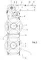
- the numeral 1 generically indicates a rigid, box-type frame comprising a base portion 1a, an upright portion 1b rising from said base portion 1a, and a top portion 1c extending horizontally from the free end of the upright portion 1b.
- Inside the upright portion 1b there are two sets of reels 2 and 3 revolvingly mounted on respective spindles 4 and 5 supported on either side, at two different heights, by the upright portion 1b.
- the two sets of reels 2 and 3 are vertically staggered so as to avoid any interference between the tapes containing the SMD being unwound therefrom.
- a shaft 7 whereon a battery of driving wheels 6 is integrally mounted for retrieving the coating film detached from the tape containing the SMD.
- the shaft 7 is connected to a geared motor 8 by means of a pulley transmission system (not shown) with a geared wheel 9, shown in figure 2.
- the top portion 1c comprises a horizontal bed 10 containing a plurality of longitudinal lanes 11, lying parallel to one another for the controlled feeding of the tape carrying the components towards a pickup area generically indicated by the numeral 12, situated at the free end of the top portion 1c.
- a pickup area generically indicated by the numeral 12
- the lanes 11 also contain respective film separators 14 consisting of suitably shaped bars, described in more detail later on.
- the delivery device 13 comprises an actuator 15, which is pneumatic in the present embodiment of the invention, solidly attached to the bed 10 with a mobile stem 16 connected by means of a bracket 20 to a transverse carriage 17 and to a block 21 sliding inside a guide (not shown) that is integral to the bed 10.
- the carriage is longitudinally movable between two stops 18 and 19.
- the pins 22 have a body 22a that fits inside a seat 23 in the carriage 17 and they are designed so that their pointed end projects from a head 17a extending crosswise over the carriage 17.
- the pins 22 are arranged vertically with their pointed ends facing the lanes 11 and they are axially mobile within the carriage 17 so that they can selectively engage in or be disengaged from the guide holes aligned along at least one side of the tape carrying the SMD, a length of which (indicated by the letter N) is shown in figure 5.
- the axial movement of the pins 22 is controlled by pneumatic actuators 24.
- the sliding lanes 11 have side walls 25 between which the film separators 14 are installed. As shown in detail in figure 6, the walls 25 frontally (i.e. in the area facing the pickup section 12) present an edge 25a that slopes in the opposite direction with respect to the pick up section 12 and, towards the bottom of the respective lane, against which a blocking pin 26 (that extends across the front end 14a of the separator 14) abuts.
- the end 14a of the separator 14 is substantially wedge-shaped so as to guide the coating film, which slides over the separator 14, coming up against its end 14a, after it has been detached from the tape carrying the SMD as a result of the tensile stress brought to bear by the respective film rewinding wheel 6 on which it is retrieved.
- the opposite edge 25b of the walls 25 slopes in the opposite direction to edge 25a and serves as a striker for a second transverse pin 27 connected to a spring (not shown) contained longitudinally inside the separator 14.
- the feeder according to the invention functions as explained below.
- the tapes containing the SMD are placed inside respective lanes 11 and the protective film, already partly detached from the respective tapes, passes over the separators 14 and is wound around respective film-retrieving driving wheels, which are at a standstill.
- the carriage 17 is in its withdrawn position up against the rear stop 18, and the pins 22 are each engaged in a hole in the respective tape.
- the geared motor 8 turns the film-retrieving driving wheels 6, which draw the coating film taut.
- the tension on the film comes to bear on the ends 14a of the separators 14, which are thus drawn back.
- the separators 14 are pushed downwards and come to rest on the tapes, holding them pressed against the bottom of their respective lanes 11.
- the tape-entraining pins 22 are withdrawn inside the carriage 17 to disengage them from the respective tapes with the exception of those engaged in the tapes selected for delivery.
- the carriage 17 advances to the front stop 19 entraining the tapes in which the selected pins 22 have remained engaged, while the drive wheels 6 continue to keep the film pulled taut.
- the tape-entraining pins 22 engaged in the selected tapes drop back into the carriage 17, thus becoming disengaged from the tape, and the carriage returns to the opposite end of its stroke 18, while the drive wheels 6 ensure the retrieval of the film detached from the selected tapes as a result of the delivery stroke. Then all the tape-entraining pins 22 re-emerge, hooking up the tapes again, while the film-retrieving drive wheels 6 stop and the feeder returns to its resting condition, ready for a new feeding cycle.
- the tapes that do not need to move forward are kept at a standstill by the separators 14 due to the effect of the tension on the films, which would normally tend to displace them.
- the second pin 27 exerts an auxiliary tensile action in the same direction as the one brought to bear by the film-retrieving wheels 6.
- This auxiliary action is useful both to reinforce the downward thrust towards the bottom of the lanes 11, which helps to hold the tapes fast therein, and to compensate for any (ultimately unavoidable) discrepancy in the turning speeds of the film-retrieving wheels 6.
- the combined and opposing action of the transverse pins 26 and 27 ensures the stable positioning of the separators 14 inside their respective lanes 11, preventing their accidental or unwanted displacement.
- the provision of a movement of the carriage 17 with a fixed stroke between the two stops 18 and 19 contributes simply and reliably to ensuring an excellent repeatability of exposure of the components.
- the assembly of the tapes on the feeder is straightforward and practical because the film separators are simply rested on the tapes and can consequently be promptly removed from their respective lanes, to allow for the positioning of the tapes, and then put back in place.
Landscapes
- Engineering & Computer Science (AREA)
- Manufacturing & Machinery (AREA)
- Microelectronics & Electronic Packaging (AREA)
- Supply And Installment Of Electrical Components (AREA)
- Casting Or Compression Moulding Of Plastics Or The Like (AREA)
- Advancing Webs (AREA)
- Replacement Of Web Rolls (AREA)
- Apparatuses And Processes For Manufacturing Resistors (AREA)
- Folding Of Thin Sheet-Like Materials, Special Discharging Devices, And Others (AREA)
- Feeding Of Articles To Conveyors (AREA)
Applications Claiming Priority (1)
| Application Number | Priority Date | Filing Date | Title |
|---|---|---|---|
| IT000232A ITFI20050232A1 (it) | 2005-11-14 | 2005-11-14 | Caricatore multiplo lineare per macchine di posizionamento automatico di componenti elettronici smd |
Publications (2)
| Publication Number | Publication Date |
|---|---|
| EP1786254A1 true EP1786254A1 (fr) | 2007-05-16 |
| EP1786254B1 EP1786254B1 (fr) | 2008-05-07 |
Family
ID=37698238
Family Applications (1)
| Application Number | Title | Priority Date | Filing Date |
|---|---|---|---|
| EP06123664A Not-in-force EP1786254B1 (fr) | 2005-11-14 | 2006-11-08 | Dispositif d'alimentation linéaire multiple pour appareils de positionnement automatique de composants electroniques de type SMD |
Country Status (7)
| Country | Link |
|---|---|
| US (1) | US7681617B2 (fr) |
| EP (1) | EP1786254B1 (fr) |
| AT (1) | ATE394914T1 (fr) |
| BR (1) | BRPI0604783A (fr) |
| DE (1) | DE602006001100D1 (fr) |
| ES (1) | ES2306382T3 (fr) |
| IT (1) | ITFI20050232A1 (fr) |
Families Citing this family (2)
| Publication number | Priority date | Publication date | Assignee | Title |
|---|---|---|---|---|
| JP5980594B2 (ja) * | 2012-06-29 | 2016-08-31 | ヤマハ発動機株式会社 | リールストッカ及び電子部品供給台車 |
| US10743446B2 (en) * | 2014-11-17 | 2020-08-11 | Fuji Corporation | Component tape feeder with reel displacing mechanism |
Citations (5)
| Publication number | Priority date | Publication date | Assignee | Title |
|---|---|---|---|---|
| US4494902A (en) * | 1981-07-29 | 1985-01-22 | U.S. Philips Corporation | Method of and device for feeding electric and/or electronic elements to given positions |
| US4586670A (en) * | 1984-12-17 | 1986-05-06 | Usm Corporation | Tape stripper for electrical component tape feeder |
| US4657158A (en) * | 1983-05-11 | 1987-04-14 | U.S. Philips Corporation | Device for feeding electronic components packed in tape to a pick-up position |
| DE4137193A1 (de) * | 1991-11-12 | 1993-05-13 | Siemens Ag | Abzugseinrichtung fuer die abdeckfolien von in gurten verpackten bauelementen |
| US5515600A (en) * | 1993-04-14 | 1996-05-14 | Kabushiki Kaisha Toshiba | Parts mounter and cartridge structure |
Family Cites Families (7)
| Publication number | Priority date | Publication date | Assignee | Title |
|---|---|---|---|---|
| JPH07114319B2 (ja) * | 1991-01-22 | 1995-12-06 | 松下電器産業株式会社 | チップ形電子部品の供給装置 |
| JPH04300126A (ja) * | 1991-03-27 | 1992-10-23 | Matsushita Electric Ind Co Ltd | 組立装置 |
| US5873691A (en) * | 1995-05-11 | 1999-02-23 | Fuji Machine Mfg. Co., Ltd. | Electronic-component supplying system |
| JP3358461B2 (ja) * | 1996-09-27 | 2002-12-16 | 松下電器産業株式会社 | 電子部品実装方法 |
| JP4041736B2 (ja) * | 2000-11-14 | 2008-01-30 | アッセンブレオン エヌ ヴィ | ピックアップ位置に電子部品を供給する装置 |
| SE522521C2 (sv) * | 2001-09-07 | 2004-02-10 | Mydata Automation Ab | Förfarande, system och arrangemang för hantering av komponenttejper |
| TWI236321B (en) * | 2003-04-10 | 2005-07-11 | Protec Co Ltd | Tape feeder for chip mounters |
-
2005
- 2005-11-14 IT IT000232A patent/ITFI20050232A1/it unknown
-
2006
- 2006-11-08 ES ES06123664T patent/ES2306382T3/es active Active
- 2006-11-08 DE DE602006001100T patent/DE602006001100D1/de active Active
- 2006-11-08 EP EP06123664A patent/EP1786254B1/fr not_active Not-in-force
- 2006-11-08 AT AT06123664T patent/ATE394914T1/de not_active IP Right Cessation
- 2006-11-10 BR BRPI0604783-1A patent/BRPI0604783A/pt not_active IP Right Cessation
- 2006-11-14 US US11/599,863 patent/US7681617B2/en not_active Expired - Fee Related
Patent Citations (5)
| Publication number | Priority date | Publication date | Assignee | Title |
|---|---|---|---|---|
| US4494902A (en) * | 1981-07-29 | 1985-01-22 | U.S. Philips Corporation | Method of and device for feeding electric and/or electronic elements to given positions |
| US4657158A (en) * | 1983-05-11 | 1987-04-14 | U.S. Philips Corporation | Device for feeding electronic components packed in tape to a pick-up position |
| US4586670A (en) * | 1984-12-17 | 1986-05-06 | Usm Corporation | Tape stripper for electrical component tape feeder |
| DE4137193A1 (de) * | 1991-11-12 | 1993-05-13 | Siemens Ag | Abzugseinrichtung fuer die abdeckfolien von in gurten verpackten bauelementen |
| US5515600A (en) * | 1993-04-14 | 1996-05-14 | Kabushiki Kaisha Toshiba | Parts mounter and cartridge structure |
Also Published As
| Publication number | Publication date |
|---|---|
| ES2306382T3 (es) | 2008-11-01 |
| US7681617B2 (en) | 2010-03-23 |
| DE602006001100D1 (de) | 2008-06-19 |
| US20070169436A1 (en) | 2007-07-26 |
| ATE394914T1 (de) | 2008-05-15 |
| EP1786254B1 (fr) | 2008-05-07 |
| BRPI0604783A (pt) | 2007-08-28 |
| ITFI20050232A1 (it) | 2007-05-15 |
Similar Documents
| Publication | Publication Date | Title |
|---|---|---|
| CA1127774A (fr) | Dispositif de montage de composants electroniques | |
| US8678065B2 (en) | Carrier tape feeder | |
| EP3250019B1 (fr) | Dispositif d'alimentation | |
| US10271469B2 (en) | Component supply device and component installation device | |
| US9820420B2 (en) | Feeder for an electronic component | |
| EP1508262B1 (fr) | Dispositif d'alimentation de bande a composants a chargement automatique | |
| CA1116646A (fr) | Courroie transporteuse sans fin inclinable pour chaine de montage automatisee | |
| KR20100087663A (ko) | 부품 공급 장치 | |
| US9901019B2 (en) | Tape feeder and method for moving a carrier tape towards a picking position in a component mounting machine | |
| JPH0157519B2 (fr) | ||
| US6368045B1 (en) | Multiple index tape feeder and method | |
| JPS61502676A (ja) | 構成部品取付機械用カセットマガジン | |
| KR102188295B1 (ko) | 부품 공급 장치, 표면 실장기, 및 부품 공급 방법 | |
| EP1786254B1 (fr) | Dispositif d'alimentation linéaire multiple pour appareils de positionnement automatique de composants electroniques de type SMD | |
| JPH08330787A (ja) | フィーダー装置 | |
| DE60121102T2 (de) | Verfahren und Vorrichtung zur Herstellung einer Filmkassette | |
| CN111564402B (zh) | 跳片自动安装机 | |
| US20020092883A1 (en) | Part feeder | |
| CN216301709U (zh) | 出料设备及供料系统 | |
| EP0471133B1 (fr) | Appareil pour saisir et guider une bande magnétique enroulée autour d'une bobine dans un appareil de chargement automatique de cassettes suivant un trajet prédéterminé | |
| KR20130088657A (ko) | 부품 실장기용 캐리어 테이프 자동공급 장치 | |
| US20260042630A1 (en) | Tape releasing device and tape loading device | |
| JP7600320B2 (ja) | 後退可能フィーダ | |
| WO2024176431A1 (fr) | Dispositif d'alimentation | |
| JPS61162423A (ja) | キヤリヤテ−プから電子部品を取り出す方法 |
Legal Events
| Date | Code | Title | Description |
|---|---|---|---|
| PUAI | Public reference made under article 153(3) epc to a published international application that has entered the european phase |
Free format text: ORIGINAL CODE: 0009012 |
|
| AK | Designated contracting states |
Kind code of ref document: A1 Designated state(s): AT BE BG CH CY CZ DE DK EE ES FI FR GB GR HU IE IS IT LI LT LU LV MC NL PL PT RO SE SI SK TR |
|
| AX | Request for extension of the european patent |
Extension state: AL BA HR MK YU |
|
| 17P | Request for examination filed |
Effective date: 20070918 |
|
| GRAP | Despatch of communication of intention to grant a patent |
Free format text: ORIGINAL CODE: EPIDOSNIGR1 |
|
| RIN1 | Information on inventor provided before grant (corrected) |
Inventor name: ARRIGHI, CLAUDIO |
|
| AKX | Designation fees paid |
Designated state(s): AT BE BG CH CY CZ DE DK EE ES FI FR GB GR HU IE IS IT LI LT LU LV MC NL PL PT RO SE SI SK TR |
|
| GRAS | Grant fee paid |
Free format text: ORIGINAL CODE: EPIDOSNIGR3 |
|
| GRAA | (expected) grant |
Free format text: ORIGINAL CODE: 0009210 |
|
| AK | Designated contracting states |
Kind code of ref document: B1 Designated state(s): AT BE BG CH CY CZ DE DK EE ES FI FR GB GR HU IE IS IT LI LT LU LV MC NL PL PT RO SE SI SK TR |
|
| REG | Reference to a national code |
Ref country code: GB Ref legal event code: FG4D |
|
| REG | Reference to a national code |
Ref country code: CH Ref legal event code: EP |
|
| REG | Reference to a national code |
Ref country code: IE Ref legal event code: FG4D Free format text: LANGUAGE OF EP DOCUMENT: FRENCH |
|
| REF | Corresponds to: |
Ref document number: 602006001100 Country of ref document: DE Date of ref document: 20080619 Kind code of ref document: P |
|
| PG25 | Lapsed in a contracting state [announced via postgrant information from national office to epo] |
Ref country code: SI Free format text: LAPSE BECAUSE OF FAILURE TO SUBMIT A TRANSLATION OF THE DESCRIPTION OR TO PAY THE FEE WITHIN THE PRESCRIBED TIME-LIMIT Effective date: 20080507 |
|
| PG25 | Lapsed in a contracting state [announced via postgrant information from national office to epo] |
Ref country code: NL Free format text: LAPSE BECAUSE OF FAILURE TO SUBMIT A TRANSLATION OF THE DESCRIPTION OR TO PAY THE FEE WITHIN THE PRESCRIBED TIME-LIMIT Effective date: 20080507 Ref country code: FI Free format text: LAPSE BECAUSE OF FAILURE TO SUBMIT A TRANSLATION OF THE DESCRIPTION OR TO PAY THE FEE WITHIN THE PRESCRIBED TIME-LIMIT Effective date: 20080507 |
|
| REG | Reference to a national code |
Ref country code: ES Ref legal event code: FG2A Ref document number: 2306382 Country of ref document: ES Kind code of ref document: T3 |
|
| NLV1 | Nl: lapsed or annulled due to failure to fulfill the requirements of art. 29p and 29m of the patents act | ||
| PG25 | Lapsed in a contracting state [announced via postgrant information from national office to epo] |
Ref country code: PL Free format text: LAPSE BECAUSE OF FAILURE TO SUBMIT A TRANSLATION OF THE DESCRIPTION OR TO PAY THE FEE WITHIN THE PRESCRIBED TIME-LIMIT Effective date: 20080507 Ref country code: AT Free format text: LAPSE BECAUSE OF FAILURE TO SUBMIT A TRANSLATION OF THE DESCRIPTION OR TO PAY THE FEE WITHIN THE PRESCRIBED TIME-LIMIT Effective date: 20080507 Ref country code: LV Free format text: LAPSE BECAUSE OF FAILURE TO SUBMIT A TRANSLATION OF THE DESCRIPTION OR TO PAY THE FEE WITHIN THE PRESCRIBED TIME-LIMIT Effective date: 20080507 |
|
| PG25 | Lapsed in a contracting state [announced via postgrant information from national office to epo] |
Ref country code: IS Free format text: LAPSE BECAUSE OF FAILURE TO SUBMIT A TRANSLATION OF THE DESCRIPTION OR TO PAY THE FEE WITHIN THE PRESCRIBED TIME-LIMIT Effective date: 20080907 |
|
| PG25 | Lapsed in a contracting state [announced via postgrant information from national office to epo] |
Ref country code: CZ Free format text: LAPSE BECAUSE OF FAILURE TO SUBMIT A TRANSLATION OF THE DESCRIPTION OR TO PAY THE FEE WITHIN THE PRESCRIBED TIME-LIMIT Effective date: 20080507 Ref country code: LT Free format text: LAPSE BECAUSE OF FAILURE TO SUBMIT A TRANSLATION OF THE DESCRIPTION OR TO PAY THE FEE WITHIN THE PRESCRIBED TIME-LIMIT Effective date: 20080507 Ref country code: DK Free format text: LAPSE BECAUSE OF FAILURE TO SUBMIT A TRANSLATION OF THE DESCRIPTION OR TO PAY THE FEE WITHIN THE PRESCRIBED TIME-LIMIT Effective date: 20080507 Ref country code: SE Free format text: LAPSE BECAUSE OF FAILURE TO SUBMIT A TRANSLATION OF THE DESCRIPTION OR TO PAY THE FEE WITHIN THE PRESCRIBED TIME-LIMIT Effective date: 20080807 |
|
| PG25 | Lapsed in a contracting state [announced via postgrant information from national office to epo] |
Ref country code: SK Free format text: LAPSE BECAUSE OF FAILURE TO SUBMIT A TRANSLATION OF THE DESCRIPTION OR TO PAY THE FEE WITHIN THE PRESCRIBED TIME-LIMIT Effective date: 20080507 Ref country code: RO Free format text: LAPSE BECAUSE OF FAILURE TO SUBMIT A TRANSLATION OF THE DESCRIPTION OR TO PAY THE FEE WITHIN THE PRESCRIBED TIME-LIMIT Effective date: 20080507 Ref country code: BE Free format text: LAPSE BECAUSE OF FAILURE TO SUBMIT A TRANSLATION OF THE DESCRIPTION OR TO PAY THE FEE WITHIN THE PRESCRIBED TIME-LIMIT Effective date: 20080507 Ref country code: PT Free format text: LAPSE BECAUSE OF FAILURE TO SUBMIT A TRANSLATION OF THE DESCRIPTION OR TO PAY THE FEE WITHIN THE PRESCRIBED TIME-LIMIT Effective date: 20081007 |
|
| PLBE | No opposition filed within time limit |
Free format text: ORIGINAL CODE: 0009261 |
|
| STAA | Information on the status of an ep patent application or granted ep patent |
Free format text: STATUS: NO OPPOSITION FILED WITHIN TIME LIMIT |
|
| 26N | No opposition filed |
Effective date: 20090210 |
|
| PG25 | Lapsed in a contracting state [announced via postgrant information from national office to epo] |
Ref country code: EE Free format text: LAPSE BECAUSE OF FAILURE TO SUBMIT A TRANSLATION OF THE DESCRIPTION OR TO PAY THE FEE WITHIN THE PRESCRIBED TIME-LIMIT Effective date: 20080507 Ref country code: BG Free format text: LAPSE BECAUSE OF FAILURE TO SUBMIT A TRANSLATION OF THE DESCRIPTION OR TO PAY THE FEE WITHIN THE PRESCRIBED TIME-LIMIT Effective date: 20080807 |
|
| PG25 | Lapsed in a contracting state [announced via postgrant information from national office to epo] |
Ref country code: MC Free format text: LAPSE BECAUSE OF NON-PAYMENT OF DUE FEES Effective date: 20081130 |
|
| PG25 | Lapsed in a contracting state [announced via postgrant information from national office to epo] |
Ref country code: IT Free format text: LAPSE BECAUSE OF FAILURE TO SUBMIT A TRANSLATION OF THE DESCRIPTION OR TO PAY THE FEE WITHIN THE PRESCRIBED TIME-LIMIT Effective date: 20080507 |
|
| PG25 | Lapsed in a contracting state [announced via postgrant information from national office to epo] |
Ref country code: IE Free format text: LAPSE BECAUSE OF NON-PAYMENT OF DUE FEES Effective date: 20081108 |
|
| PG25 | Lapsed in a contracting state [announced via postgrant information from national office to epo] |
Ref country code: LU Free format text: LAPSE BECAUSE OF NON-PAYMENT OF DUE FEES Effective date: 20081108 Ref country code: CY Free format text: LAPSE BECAUSE OF FAILURE TO SUBMIT A TRANSLATION OF THE DESCRIPTION OR TO PAY THE FEE WITHIN THE PRESCRIBED TIME-LIMIT Effective date: 20080507 Ref country code: HU Free format text: LAPSE BECAUSE OF FAILURE TO SUBMIT A TRANSLATION OF THE DESCRIPTION OR TO PAY THE FEE WITHIN THE PRESCRIBED TIME-LIMIT Effective date: 20081108 |
|
| PG25 | Lapsed in a contracting state [announced via postgrant information from national office to epo] |
Ref country code: TR Free format text: LAPSE BECAUSE OF FAILURE TO SUBMIT A TRANSLATION OF THE DESCRIPTION OR TO PAY THE FEE WITHIN THE PRESCRIBED TIME-LIMIT Effective date: 20080507 |
|
| PG25 | Lapsed in a contracting state [announced via postgrant information from national office to epo] |
Ref country code: GR Free format text: LAPSE BECAUSE OF FAILURE TO SUBMIT A TRANSLATION OF THE DESCRIPTION OR TO PAY THE FEE WITHIN THE PRESCRIBED TIME-LIMIT Effective date: 20080808 |
|
| REG | Reference to a national code |
Ref country code: CH Ref legal event code: PL |
|
| PG25 | Lapsed in a contracting state [announced via postgrant information from national office to epo] |
Ref country code: CH Free format text: LAPSE BECAUSE OF NON-PAYMENT OF DUE FEES Effective date: 20101130 Ref country code: LI Free format text: LAPSE BECAUSE OF NON-PAYMENT OF DUE FEES Effective date: 20101130 |
|
| PGFP | Annual fee paid to national office [announced via postgrant information from national office to epo] |
Ref country code: FR Payment date: 20121130 Year of fee payment: 7 |
|
| PGFP | Annual fee paid to national office [announced via postgrant information from national office to epo] |
Ref country code: GB Payment date: 20121120 Year of fee payment: 7 Ref country code: ES Payment date: 20121127 Year of fee payment: 7 |
|
| PGFP | Annual fee paid to national office [announced via postgrant information from national office to epo] |
Ref country code: DE Payment date: 20131121 Year of fee payment: 8 |
|
| GBPC | Gb: european patent ceased through non-payment of renewal fee |
Effective date: 20131108 |
|
| REG | Reference to a national code |
Ref country code: FR Ref legal event code: ST Effective date: 20140731 |
|
| PG25 | Lapsed in a contracting state [announced via postgrant information from national office to epo] |
Ref country code: GB Free format text: LAPSE BECAUSE OF NON-PAYMENT OF DUE FEES Effective date: 20131108 Ref country code: FR Free format text: LAPSE BECAUSE OF NON-PAYMENT OF DUE FEES Effective date: 20131202 |
|
| REG | Reference to a national code |
Ref country code: DE Ref legal event code: R119 Ref document number: 602006001100 Country of ref document: DE |
|
| REG | Reference to a national code |
Ref country code: ES Ref legal event code: FD2A Effective date: 20150708 |
|
| PG25 | Lapsed in a contracting state [announced via postgrant information from national office to epo] |
Ref country code: ES Free format text: LAPSE BECAUSE OF NON-PAYMENT OF DUE FEES Effective date: 20131109 |
|
| PG25 | Lapsed in a contracting state [announced via postgrant information from national office to epo] |
Ref country code: DE Free format text: LAPSE BECAUSE OF NON-PAYMENT OF DUE FEES Effective date: 20150602 |