EP1787564B1 - Plaque de fixation avec dispositif de déviation pour un sac à poussières d'aspirateur - Google Patents
Plaque de fixation avec dispositif de déviation pour un sac à poussières d'aspirateur Download PDFInfo
- Publication number
- EP1787564B1 EP1787564B1 EP06006750.1A EP06006750A EP1787564B1 EP 1787564 B1 EP1787564 B1 EP 1787564B1 EP 06006750 A EP06006750 A EP 06006750A EP 1787564 B1 EP1787564 B1 EP 1787564B1
- Authority
- EP
- European Patent Office
- Prior art keywords
- holding plate
- deflection device
- vacuum cleaner
- plate according
- passage opening
- Prior art date
- Legal status (The legal status is an assumption and is not a legal conclusion. Google has not performed a legal analysis and makes no representation as to the accuracy of the status listed.)
- Expired - Lifetime
Links
Images


Classifications
-
- A—HUMAN NECESSITIES
- A47—FURNITURE; DOMESTIC ARTICLES OR APPLIANCES; COFFEE MILLS; SPICE MILLS; SUCTION CLEANERS IN GENERAL
- A47L—DOMESTIC WASHING OR CLEANING; SUCTION CLEANERS IN GENERAL
- A47L9/00—Details or accessories of suction cleaners, e.g. mechanical means for controlling the suction or for effecting pulsating action; Storing devices specially adapted to suction cleaners or parts thereof; Carrying-vehicles specially adapted for suction cleaners
- A47L9/10—Filters; Dust separators; Dust removal; Automatic exchange of filters
- A47L9/14—Bags or the like; Rigid filtering receptacles; Attachment of, or closures for, bags or receptacles
-
- A—HUMAN NECESSITIES
- A47—FURNITURE; DOMESTIC ARTICLES OR APPLIANCES; COFFEE MILLS; SPICE MILLS; SUCTION CLEANERS IN GENERAL
- A47L—DOMESTIC WASHING OR CLEANING; SUCTION CLEANERS IN GENERAL
- A47L9/00—Details or accessories of suction cleaners, e.g. mechanical means for controlling the suction or for effecting pulsating action; Storing devices specially adapted to suction cleaners or parts thereof; Carrying-vehicles specially adapted for suction cleaners
- A47L9/10—Filters; Dust separators; Dust removal; Automatic exchange of filters
- A47L9/14—Bags or the like; Rigid filtering receptacles; Attachment of, or closures for, bags or receptacles
- A47L9/1427—Means for mounting or attaching bags or filtering receptacles in suction cleaners; Adapters
-
- A—HUMAN NECESSITIES
- A47—FURNITURE; DOMESTIC ARTICLES OR APPLIANCES; COFFEE MILLS; SPICE MILLS; SUCTION CLEANERS IN GENERAL
- A47L—DOMESTIC WASHING OR CLEANING; SUCTION CLEANERS IN GENERAL
- A47L9/00—Details or accessories of suction cleaners, e.g. mechanical means for controlling the suction or for effecting pulsating action; Storing devices specially adapted to suction cleaners or parts thereof; Carrying-vehicles specially adapted for suction cleaners
- A47L9/10—Filters; Dust separators; Dust removal; Automatic exchange of filters
- A47L9/14—Bags or the like; Rigid filtering receptacles; Attachment of, or closures for, bags or receptacles
- A47L9/1427—Means for mounting or attaching bags or filtering receptacles in suction cleaners; Adapters
- A47L9/1436—Connecting plates, e.g. collars, end closures
-
- A—HUMAN NECESSITIES
- A47—FURNITURE; DOMESTIC ARTICLES OR APPLIANCES; COFFEE MILLS; SPICE MILLS; SUCTION CLEANERS IN GENERAL
- A47L—DOMESTIC WASHING OR CLEANING; SUCTION CLEANERS IN GENERAL
- A47L9/00—Details or accessories of suction cleaners, e.g. mechanical means for controlling the suction or for effecting pulsating action; Storing devices specially adapted to suction cleaners or parts thereof; Carrying-vehicles specially adapted for suction cleaners
- A47L9/10—Filters; Dust separators; Dust removal; Automatic exchange of filters
- A47L9/14—Bags or the like; Rigid filtering receptacles; Attachment of, or closures for, bags or receptacles
- A47L9/1427—Means for mounting or attaching bags or filtering receptacles in suction cleaners; Adapters
- A47L9/1436—Connecting plates, e.g. collars, end closures
- A47L9/1445—Connecting plates, e.g. collars, end closures with closure means
- A47L9/1454—Self-sealing closures, e.g. valves
Definitions
- the invention relates to a holding plate for a vacuum cleaner filter bag, which is attachable to a holding device in a vacuum cleaner housing for holding the vacuum cleaner filter bag.
- vacuum cleaners which work with vacuum cleaner filter bags
- the latter are arranged in the housing of the vacuum cleaner.
- a holding plate is provided on the filter bag, which is attached to a holding device in the vacuum cleaner housing, so that in this way the vacuum cleaner filter bag is held in the housing.
- Such holding plates are often glued or welded in conventional vacuum cleaner filter bags with the filter material of the bag. Since the holding devices of different types of vacuum cleaner generally differ, for each different type of vacuum cleaner, a corresponding vacuum cleaner filter bag must be made and purchased with matching holding plate.
- adapter plates that are each tuned to a holding device of a particular vacuum cleaner.
- This adapter plate is designed so that it can be releasably connected to a universal vacuum cleaner filter bag. In this way, it is sufficient to provide different adapter plates for the different vacuum cleaners or their holding devices, although a uniform filter bag can be used.
- Such adapter plates are for example from the WO 00/36966 , of the DE 20 2005 010606 or the EP 1 607 034 known.
- a vacuum cleaner filter bag with a filter structure in which a coarse filter layer is arranged in front of a fine filter layer in the direction of the air flow.
- the coarse filter has a high dust storage capacity, so that dust particles in its pores can be stored over the entire thickness. In this way, a clogging of the filter material is delayed and thus increases the service life of the bag.
- a holding plate for a vacuum cleaner filter bag which comprises a slip-on sleeve for the bag. Clamping blocks are provided which secure the filter bag.
- the US 5,544,385 disclosed an assembly for securing a filter bag in a vacuum cleaner.
- a solid plate is fastened to the housing of the vacuum cleaner.
- An air deflector extends from the fixed plate so that it is inserted into the filter bag when inserted into the vacuum cleaner.
- the BE 529 649 discloses a closure element for the opening in a vacuum cleaner bag, wherein the closure element may be formed as a flexible band in the form of a loop.
- the dirt collector is part of a connecting element and extends transversely to the direction of movement of the air to be filtered.
- the dirt trap does not extend over the entire area of the opening provided for the air to be filtered in the connecting element.
- a holding plate for a vacuum cleaner filter bag which is attachable to a holding device in a vacuum cleaner housing for holding the vacuum cleaner filter bag, with a base plate in which a passage opening is formed for an air flow, a fastening device connected to the base plate for non-destructively detachable connection of the retaining plate to a vacuum cleaner filter bag, and a deflector at least partially surrounding the deflector, which is connected to the base plate and is formed so that it is at least partially disposed in the bag interior after connecting the holding plate with a vacuum cleaner filter bag and an entering through the passage opening in the deflector air flow in the deflector is deflected
- the deflecting device comprises at least one, preferably flat, deflection surface opposite the passage opening; and wherein the at least one deflection surface has a larger area than the area of the passage opening.
- the deflecting device may in particular comprise at least one outflow opening, which is arranged in the bag interior after connecting the holding plate to the vacuum cleaner filter bag, so that a deflected in the deflector air flow can flow into the bag interior.
- the at least one deflection or baffle surface opposite the passage opening can in particular reduce the velocity of the particles in a suitable manner.
- the distance or the average distance of such a deflection of the Passage opening may depend in particular on the size and shape of the vacuum cleaner filter bag or vacuum cleaner, for which such a holding plate should be provided.
- Each deflection surface may have an area of 15 to 100 cm 2 , in particular 40 to 60 cm 2 .
- the baffle is formed as part of a retainer plate which also has attachment means for non-destructively detachable connection to a vacuum cleaner filter bag
- a retrofit member is provided in this manner which can be connected to a variety of vacuum cleaner filter bags as far as they are for connection to the retainer plate are formed suitable. This further allows that the vacuum cleaner filter bag itself can be made only with little effort, since the deflector is provided on the side of the holding plate. This, on the one hand, reduces the complexity of the manufacturing process of the filter bags; on the other hand, the filter bags can be folded to smaller dimensions and / or pack.
- flow direction of the air flow or air flow direction is meant the main flow direction of the air, which runs generally parallel to a wall, for example a vacuum cleaner pipe or nozzle.
- main flow direction results at any point through a vacuum cleaner tube into the bag, even if turbulence may possibly occur at individual points.
- the deflection device can in particular be non-destructively releasably connected to the base plate.
- the fastening device can be designed to form a non-positive or a positive connection.
- the fastening device can be designed to form a screw, wedge, pin, Velcro or snap connection.
- the deflection device can be designed to split the air flow into at least two partial flows with different flow directions.
- the at least one deflection surface can be arranged at a predetermined angle relative to the plane of the passage opening, in particular parallel to the plane of the passage opening.
- the deflection of the air flow to different parameters such as inlet angle, geometry or dimensioning of a vacuum cleaner housing and / or bag can be adjusted and optimized.
- air flow is deflected or deflected by about 90 °, which has a favorable distribution of the particles and the resulting filter cake in the filter bag result.
- a deflection surface opposite the passage opening can have a distance or an average distance of between 0.5 cm and 5 cm, in particular 2.5 cm to 4 cm, in particular from the latter.
- the deflection device can be designed, in particular, for dividing the air flow into at least two partial flows with opposite directions of flow.
- Opposing flow directions means that both flow directions have a component in the plane perpendicular to the flow direction, with which an air flow enters the deflection device through the passage opening, ie a component perpendicular to the inlet flow direction, wherein the components enclose an angle of approximately 180 ° and the components in this plane are each larger than the corresponding component parallel to the inlet flow direction.
- the deflecting device can be designed such that an air flow passing into the deflecting device in the deflecting device can be deflected by at least 45 °, preferably at least 60 °, more preferably at least 80 °, compared to the air flow at the passage opening.
- the air flow direction forms an angle of at least 45 ° when exiting the deflecting device with the flow direction at the passage opening. This results in a particularly advantageous air flow direction in a vacuum cleaner filter bag.
- the deflection device of the retaining plates described above can have two trapezoidal or rectangular deflection surfaces which, starting from the passage opening, run in a wedge shape towards one another and are connected to one another at a connecting edge opposite the passage opening.
- such a deflecting device may further comprise at at least one end of the connecting edge an outflow opening and a region surrounding the passage opening and connected to the base plate, which is designed in the manner of a block bottom and has an inflow opening.
- the deflection device of the retaining plates described above may, in an alternative development, have the shape of a cuboid which has an inflow opening in the cover surface surrounding the passage opening and connected to the base plate and an outflow opening in at least one side face.
- the cuboid shape achieves a stable construction of the deflection device, with a suitable deflecting or baffle surface being simultaneously formed for deflecting the air flow through the base surface of the cuboid opposite the inflow opening.
- the base surface of the cuboid may have at least one opening, which forms an outflow opening with an opening in a side surface.
- the base surface of the cuboid deflector may have at least one opening, which forms an outflow opening with an opening in a side surface.
- the distance between the side surface of the cuboid deflector and the bag wall due to the geometry of the bag and the vacuum cleaner housing is low (for example, in American upright vacuum cleaners), so that at an outflow only in a sidewall a clogging problem may occur.
- each outflow opening can occupy substantially the entire width of the side surface of the cuboid. This avoids that in the operation of the holding plate in a corner of the cuboid sucked in dust particles accumulate.
- a deflection device provided in the form of a cuboid, in particular at least two opposite outflow openings can be provided.
- the retaining plates described above may have a deflection device, which is designed in such a way that, in a first position, it has a reduced extent, compared to a second position, perpendicular to the plane of the passage opening.
- the holding plate Due to the smaller extent in the second position, the holding plate can be brought into a very compact form. Thus, the holding plate can be packaged and transported in an advantageous manner.
- the deflection device may be formed substantially flat in the first position.
- the deflecting device may be designed such that it assumes the first position when the holding plate is not supported by the holding device, and that it can be brought into the second position when the vacuum cleaner filter bag is held by the holding device.
- the deflecting device can thus be brought to the second position already when attaching the holding plate to the holding device. Upon removal from the fixture, the deflector will return to the first position.
- the deflecting device can be brought into the second position when the holding device is brought into position, which it occupies during operation of the vacuum cleaner.
- the deflector automatically returns to the first position.
- the deflector can be brought by a vacuum cleaner side provided element in the second position and by this element again in the first position.
- a vacuum cleaner side provided element may for example be designed such that it moves when turning on the vacuum cleaner so that the deflector is brought into the second position; when switching off then takes place a reverse movement, which makes it possible that the deflector returns to the first position.
- the deflection device may be designed such that it can be brought from the first position to the second position by a suction air flow. In this way, it is possible that the holding plate with its deflector passes by the resulting due to the suction of air in the bag negative pressure in the vacuum cleaner in its operating position in which the deflector fulfills its deflection.
- the deflecting device may comprise a restoring element, in particular a spring element, which exerts a restoring force on a part of the deflecting device in such a way that the deflecting device can be brought from the second position into the first position.
- Such a return element allows the deflector on release of the suction air flow, for example, when the vacuum cleaner is switched from the second position back to the first position with reduced extension perpendicular to the plane of the passage opening.
- the deflection device can have fold lines or film hinges, with the result that the deflection device can be brought from the first or second position into the second or first position.
- fold lines or film hinges allow the desired folding or folding in a simple and reliable manner.
- the deflecting device can also be rigid, so that collapsing is not possible.
- the deflecting device can furthermore be designed to close the passage opening.
- the deflection device may comprise a spring element which exerts a restoring force on a part of the deflection device in order to close the passage opening.
- the holding plates described above may comprise a sealing element, in particular for sealing the passage opening.
- the passage opening can be sealed by a nozzle introduced during operation of the vacuum cleaner.
- the sealing element can in particular be connected to the base plate on its side facing the deflection device and / or arranged inside the deflection device. This reduces the risk of damaging the sealing element.
- the sealing element may in particular comprise rubber, an elastomer, a foil or a foam, in particular a closed-cell foam.
- the holding plate may comprise a sprayed onto the base plate foam, which is provided on the side facing the deflector surrounding the passage opening so that it enters the passage opening when connecting the holding plate with a vacuum cleaner filter bag.
- the base plate of the holding plate may in particular comprise cardboard or a plastic.
- the deflection device may comprise a plastic, a dry or wet-laid nonwoven or paper, in particular cardboard, or a film. Both for the deflection and for the base plate other materials are possible, but it is sufficient rigidity of the material beneficial.
- the fastening device may in particular comprise a plastic or cardboard.
- the base plate and the deflection device and, if necessary, the fastening device may comprise the same material.
- a vacuum cleaner filter bag for connection to one of the above-described holding plates with a counter attachment means adapted to cooperate with the attachment means, such that the holding plate is connectable to the vacuum cleaner filter bag.
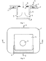
- FIG. 1 schematically illustrates a cross-sectional view of a holding plate 1 according to the invention.
- the holding plate comprises a base plate 2, a deflection device 3 and a fastening device 4.
- the base plate 2, the deflector 3 and the fastening device 4 may each consist of a plastic.
- the entire holding plate may be formed as an injection molded part.
- the base plate 2 is formed so that it can be connected to a holding device of a vacuum cleaner so that it can be held in a vacuum cleaner housing.
- FIG. 2 A plan view of a holding plate 1 connected to a vacuum cleaner filter bag 5 is shown in FIG. 2 shown.
- This holding plate 1 is in a holding device 6, which may be particularly firmly connected to the vacuum cleaner housing, plugged and is supported in this manner.
- the cross-sectional view along the line II is in FIG. 1 shown.
- the base plate 2 of the retaining plate 1 has a passage opening 7, through which an air flow during operation can enter the deflection device and then into the vacuum cleaner filter bag.
- the deflector 3 connected to the base plate 2 has a cylindrical shape.
- the Side wall of the deflector is connected at its upper end to the base plate 2 and surrounds the passage opening 7.
- the cylinder 3 forming the deflector is open at the top, so that in this way an inlet opening is formed in the deflector.
- the base plate of the cylinder is opposite to the passage opening 7 and parallel to the plane of the passage opening.
- a deflection 8 is formed in the side wall of the deflector in the side wall of the deflector two opposite outflow openings 9 are provided.
- the deflection device may alternatively also have only one outflow opening or more than two outflow openings.
- the height of the deflector can be between 1 cm and 5 cm, in particular between 2 cm and 4 cm, and the diameter between 3 cm and 9 cm, preferably 5 cm and 8 cm.
- the holding plate 1 also has a fastening device 4, which is also cylindrical in the illustrated example and surrounds the passage opening 7.
- the fastening device 4 comprises an external thread (not shown).
- On the vacuum cleaner filter bag 5 a counter attachment 10 is attached.
- This fastening counterpart device comprises, in particular, an internal thread corresponding to the external thread of the fastening device 4.
- the attachment counter-device 10 is fixedly connected to the bag wall of the vacuum cleaner filter bag 5, for example glued or welded. In this way, the holding plate 1 can be screwed to the vacuum cleaner filter bag, whereby a secure connection is achieved.
- the holding plate 1 further comprises a sealing element 11, which is a ring made of a flexible material surrounding the passage opening 7. Through this ring a plugged into the passage opening (for connection to a vacuum cleaner tube) is sealed.
- the bag wall of the vacuum cleaner filter bag for example, have a structure as shown in the EP 0 960 645 is described.
- a coarse filter layer for example from a meltblown
- a fine filter layer for example likewise from a meltblown.
- further layers may be provided in the filter structure, for example support layers and / or odor-absorbing layers.
- FIGS. 3 and 4 illustrate another embodiment of a retaining plate with a deflector. It shows FIG. 3 schematically a cross section of the holding plate, in which the deflector assumes its first position in which they, in comparison with the in FIG. 4 Having shown second position, a smaller extent perpendicular to the plane of the passage opening 7.
- the cross-sectional view in the FIGS. 3 and 4 corresponds to the cross section along the line II-II in FIG. 2 ,
- the in these FIGS. 3 and 4 Holding plate 1 shown also includes a deflector 3, which here, however, has a cuboid shape.
- the base 8 of the cuboid is arranged parallel to the plane of the passage opening 7. This base also serves to close the passage opening.
- a further sealing element 12 is provided on the base 8 of the cuboid. This serves to seal the passage opening in the first position of the closure device tight.
- the further sealing element 12 may in particular be adapted to the opening in the first sealing element 11.
- the sealing elements 11 and 12 can be made by using a continuous, i. the passage opening overlapping, sealing material is disposed in the interior of the deflector.
- This may be, for example, a closed-cell foam, into which an opening is subsequently punched during production in order to expose an inflow opening in the cuboid.
- the punched out material can then be arranged on the base 8 of the cuboid.
- a bending spring 13 which may be, for example, cambered provided.
- the spring force is a restoring force on the deflector exercised, so that these in principle their in FIG. 3 shown closed position occupies.
- the bending spring 13 may be glued, for example, with the base surface and a side surface of the cuboid.
- the spring can also be arranged in another way.
- the deflection device may be at least partially double-layered (for example with two layers of cardboard), wherein the spring is arranged between the two layers. The layers are glued together leaving a non-bonded gap for the spring; the spring itself then need not be glued to one of the layers; Alternatively, it may also be firmly connected to one or both layers only at one end.
- the sealing element 12 can penetrate into the opening of the sealing element 11 differently far in the first position of the deflecting device.
- a permanent magnet can also be provided in or on the base plate 2 and a ferromagnetic element in or on one of the side surfaces or the base surface of the deflection device.
- a return device is also formed, which allows a folding of the deflection.
- the spring 13 may be formed such that in operation of the vacuum cleaner, the force caused by a suction air flow is sufficient to bring the deflector from the first position to the second position. When you turn off the vacuum cleaner then the restoring force of the spring acts such that the passage opening is closed again.
- the fastening device 4 is a hook-and-loop fastener element.
- a corresponding Velcro counter element 10 is then arranged, so that the holding plate can be securely connected to the vacuum cleaner filter bag.
- the hook-and-loop fastener element can, for example, be glued or welded to the bag wall.
- the dimensions of the cuboid deflection devices can be, for example, 7.5 cm ⁇ 8 cm ⁇ 3 cm (width ⁇ depth ⁇ height).
- the material may be cardboard, for example.
- the deflection can be glued, for example, with a base plate made of plastic.
- the surface of the deflection device facing the base plate 2 may be coated with a plastic corresponding to the base plate so that the base plate 2 and the deflection device 3 can be welded together.
- a plastic for example polypropylene may be provided.
- outflow openings are provided in the two parallel to the plane of the side surfaces of the cuboid deflection, which in particular each occupy the entire side surface of the cuboid.
- At the edges between the baffle plate 8 and the two other side surfaces or between the two side surfaces and the top surface with the inlet opening in the deflection folding lines 14 are provided which allow a folding of the deflector to the extent of the deflector perpendicular to the plane of the passage opening out.
- part of the base area of a cuboid deflection device may be removed, so that a common outflow opening is formed by both. This can be avoided that a relatively narrow gap between the deflector and bag wall clogged during operation.
- the deflection device may be formed and / or arranged on the base plate, that they the position according to FIG. 3 occupies, if the vacuum cleaner filter bag is not held with the holding plate in the vacuum cleaner housing.
- the deflector is by contact, for example, with a housing in the position according to FIG. 4 brought.
- the two side walls welded together along the edge are at least partially moved apart in this way, so that the volume increases in the interior. This also allows a flat bag with a side gusset in an upright vacuum cleaner use.
- the deflector may be formed by a strip of material from a film or a non-woven fabric.
- a holding plate 1 with such a flexible deflecting device 3 is in FIG. 5 shown schematically.
- Such a Strip can be connected at its two ends to the base plate so that it hangs in front of the passage opening 7. In this way, two outflow openings are also formed.
- the film of the deflector 3 made of the same material as the base plate 2 and be injected in one operation.
- the film can be made of a different material and sprayed in a second operation to a base plate (2K injection molding).
- the production can be carried out by means of insert molding or subsequent gluing or welding. If a thermoplastic elastomer is used, the sealing member 11 may be formed simultaneously.
- FIG. 6 Another embodiment is shown schematically in a cross-sectional view in FIG. 6 shown.
- the deflector 3 can be folded in the manner of a concertina.
- the two left and right side surfaces each have in their middle a parallel to the base surface extending fold line 14 on which the side surface can be kinked.
- a permanent magnet (not shown) in or on the base plate 2 and a ferromagnetic element (not shown) may be provided in or on one of the side surfaces or the base of the deflector 3.
- a ferromagnetic element may be provided in or on one of the side surfaces or the base of the deflector 3.
- a suction air flow acts on the base of the deflection a force to move them in the direction of the base plate.
- the deflection device may also have a wedge-shaped or wedge-like shape.
- the deflector may be formed like a reduced filter bag with block bottom, but without its own holding plate or the like.
- the block bottom is connected to the inlet opening with the bag facing side of the holding plate; in the two narrow side surfaces of the deflector two holes are cut at the wedge tip as discharge openings.
- the incoming air is formed by the wide side surfaces and the spiral fold with the connecting edge or in the region of the Wickelfalzes Surface deflected by the discharge opening.
- the advantage of this shape of the deflector is that it can also be folded in a simple manner. Further designs of the deflection device are also possible.
Landscapes
- Engineering & Computer Science (AREA)
- Mechanical Engineering (AREA)
- Filters For Electric Vacuum Cleaners (AREA)
Claims (21)
- Plaque d'embout de maintien (1) pour un sac filtrant d'aspirateur (5), qui peut être rapportée sur un dispositif de support de maintien (6) dans un boitier ou carter d'aspirateur en vue de maintenir le sac filtrant d'aspirateur (5), comprenant
une plaque de base (2) dans laquelle est formée une ouverture de passage (7) pour un flux d'air,
un dispositif de fixation (4) relié à la plaque de base (2) pour assurer une liaison pouvant être interrompue de façon non destructive, de la plaque d'embout de maintien (1) avec un sac filtrant d'aspirateur (5), et
un dispositif déflecteur (3), qui entoure au moins partiellement l'ouverture de passage (7), et qui est relié à la plaque de base (2) et conçu de manière à se retrouver, après la liaison de la plaque d'embout de maintien (1) avec un sac filtrant d'aspirateur (5), au moins partiellement à l'intérieur du sac, et de façon à ce qu'un flux d'air pénétrant dans le dispositif déflecteur (3) à travers l'ouverture de passage (7), puisse être dévié dans le dispositif déflecteur (3) ;
le dispositif déflecteur (3) présentant au moins une surface déflectrice (8), de préférence plane, située en regard de l'ouverture de passage (7)
caractérisée en ce que
ladite au moins une surface déflectrice (8) présente une surface plus grande que la surface de l'ouverture de passage (7). - Plaque d'embout de maintien selon la revendication 1, dans laquelle le dispositif de fixation est conçu pour réaliser une liaison par adhérence ou par complémentarité de formes.
- Plaque d'embout de maintien selon la revendication 2, dans laquelle le dispositif de fixation est conçu pour réaliser une liaison par vissage, une liaison à coin, à broche, une liaison auto-agrippante ou une liaison par encliquetage.
- Plaque d'embout de maintien selon l'une des revendications précédentes, dans laquelle le dispositif déflecteur est conçu pour subdiviser le flux d'air en au moins deux flux partiels avec des directions d'écoulement de flux différentes.
- Plaque d'embout de maintien selon la revendication 1, dans laquelle ladite au moins une surface déflectrice est agencée selon un angle prédéterminé par rapport au plan de l'ouverture de passage.
- Plaque d'embout de maintien selon l'une des revendications précédentes, dans laquelle le dispositif déflecteur présente deux surfaces déflectrices de forme trapézoïdale ou rectangulaire, qui, à partir de l'ouverture de passage, se dirigent l'une vers l'autre en forme de coin et sont reliées mutuellement le long d'un bord de liaison situé en regard de l'ouverture de passage.
- Plaque d'embout de maintien selon la revendication 6, dans laquelle le dispositif déflecteur comprend, en outre, une ouverture de sortie d'écoulement de flux à au moins une extrémité du bord de liaison, et une zone entourant l'ouverture de passage et reliée au côté intérieur du sac, qui est réalisée à la manière d'un fond à soufflets et présente une ouverture d'entrée d'écoulement de flux.
- Plaque d'embout de maintien selon l'une des revendications 1-5, dans laquelle le dispositif déflecteur présente la forme d'un parallélépipède qui comporte, dans la surface supérieure entourant l'ouverture de passage et reliée à la plaque de base, une ouverture d'entrée d'écoulement de flux, et une ouverture de sortie d'écoulement de flux (9) dans au moins une surface latérale.
- Plaque d'embout de maintien selon la revendication 8, dans laquelle chaque ouverture de sortie d'écoulement de flux occupe sensiblement la totalité de la largeur de la surface latérale du parallélépipède.
- Plaque d'embout de maintien selon l'une des revendications 7-9, dans laquelle sont prévues au moins deux ouvertures de sortie d'écoulement de flux mutuellement en regard l'une de l'autre.
- Plaque d'embout de maintien selon l'une des revendications précédentes, dans laquelle le dispositif déflecteur est conçu de manière à présenter une étendue perpendiculairement au plan de l'ouverture de passage, qui est réduite dans une première position par rapport à une deuxième position.
- Plaque d'embout de maintien selon la revendication 11, dans laquelle le dispositif déflecteur est conçu de manière à occuper la première position lorsque la plaque d'embout de maintien n'est pas supportée par le dispositif de support de maintien, et de manière à pouvoir être amené dans la deuxième position lorsque le sac filtrant d'aspirateur est maintenu par le dispositif de support de maintien.
- Plaque d'embout de maintien selon la revendication 11, dans laquelle le dispositif déflecteur est conçu de manière à pouvoir être amené de la première position à la deuxième position sous l'effet d'un flux d'air d'aspiration.
- Plaque d'embout de maintien selon l'une des revendications 11-13, dans laquelle le dispositif déflecteur comprend un élément de rappel (13), qui exerce une force de rappel sur une partie du dispositif déflecteur de manière telle que le dispositif déflecteur puisse être amené de la deuxième position à la première position.
- Plaque d'embout de maintien selon l'une des revendications 11-14, dans laquelle le dispositif déflecteur présente des lignes de pliage ou des charnières à film (14), de sorte que le dispositif déflecteur peut être amené de la première ou de la deuxième position à la deuxième et respectivement à la première position.
- Plaque d'embout de maintien selon l'une des revendications précédentes, dans laquelle le dispositif déflecteur est conçu pour fermer l'ouverture de passage.
- Plaque d'embout de maintien selon l'une des revendications précédentes, comprenant un élément d'étanchéité (11 ; 12), notamment pour assurer l'étanchéité de l'ouverture de passage.
- Plaque d'embout de maintien selon la revendication 17, dans laquelle l'élément d'étanchéité est relié à la plaque de base sur son côté dirigé vers le dispositif déflecteur, et/ou est agencé à l'intérieur du dispositif déflecteur.
- Plaque d'embout de maintien selon la revendication 17 ou la revendication 18, dans laquelle l'élément d'étanchéité comporte du caoutchouc, un élastomère, une feuille ou une mousse.
- Plaque d'embout de maintien selon l'une des revendications précédentes, dans laquelle le dispositif déflecteur comprend une matière plastique, un non tissé de fibres obtenu par voie sèche ou humide, du papier, notamment du carton, ou une feuille.
- Plaque d'embout de maintien selon l'une des revendications précédentes, dans laquelle la plaque de base est réalisée d'un seul tenant avec le dispositif déflecteur et/ou avec le dispositif de fixation.
Priority Applications (2)
| Application Number | Priority Date | Filing Date | Title |
|---|---|---|---|
| EP06006750.1A EP1787564B1 (fr) | 2005-11-22 | 2006-03-30 | Plaque de fixation avec dispositif de déviation pour un sac à poussières d'aspirateur |
| PL06006750T PL1787564T3 (pl) | 2005-11-22 | 2006-03-30 | Płyta nośna z urządzeniem odchylającym do worka filtrującego do odkurzacza |
Applications Claiming Priority (4)
| Application Number | Priority Date | Filing Date | Title |
|---|---|---|---|
| EP05025480 | 2005-11-22 | ||
| EP05027013A EP1787560B1 (fr) | 2005-11-22 | 2005-12-09 | Sac à poussières d'aspirateur avec dispositif de déviation |
| EP06003723.1A EP1787562B1 (fr) | 2005-11-22 | 2006-02-23 | Raccord avec dispositif de déviation pour un aspirateur |
| EP06006750.1A EP1787564B1 (fr) | 2005-11-22 | 2006-03-30 | Plaque de fixation avec dispositif de déviation pour un sac à poussières d'aspirateur |
Publications (3)
| Publication Number | Publication Date |
|---|---|
| EP1787564A2 EP1787564A2 (fr) | 2007-05-23 |
| EP1787564A3 EP1787564A3 (fr) | 2009-12-09 |
| EP1787564B1 true EP1787564B1 (fr) | 2014-10-22 |
Family
ID=37761914
Family Applications (1)
| Application Number | Title | Priority Date | Filing Date |
|---|---|---|---|
| EP06006750.1A Expired - Lifetime EP1787564B1 (fr) | 2005-11-22 | 2006-03-30 | Plaque de fixation avec dispositif de déviation pour un sac à poussières d'aspirateur |
Country Status (2)
| Country | Link |
|---|---|
| EP (1) | EP1787564B1 (fr) |
| PL (1) | PL1787564T3 (fr) |
Families Citing this family (2)
| Publication number | Priority date | Publication date | Assignee | Title |
|---|---|---|---|---|
| EP2712532A3 (fr) * | 2012-09-28 | 2015-07-01 | Roland Kuhblank | Système de sac anti-poussière pour aspirateurs |
| DK3042598T3 (en) * | 2013-06-25 | 2018-05-22 | Ando Filtersysteme Gmbh | Dust bag system for vacuum cleaners |
Citations (1)
| Publication number | Priority date | Publication date | Assignee | Title |
|---|---|---|---|---|
| US3675399A (en) * | 1969-04-21 | 1972-07-11 | Whirlpool Co | Vacuum cleaner |
Family Cites Families (12)
| Publication number | Priority date | Publication date | Assignee | Title |
|---|---|---|---|---|
| BE529649A (fr) * | 1953-06-16 | 1957-07-05 | Tornado Sa | Obturateur de recipient s'ouvrant automatiquement dans le sens du remplissage |
| FR1148583A (fr) * | 1956-02-23 | 1957-12-11 | Tornado A G | Collecteur de poussières pour aspirateur et aspirateur muni de ce dispositif |
| US3973936A (en) * | 1975-01-28 | 1976-08-10 | Sol Howard | Horseshoe-shaped vacuum cleaner filter bag |
| US4469498A (en) * | 1982-09-29 | 1984-09-04 | Whirlpool Corporation | Dirt interceptor filter bag mount for vacuum cleaner |
| US5544385A (en) * | 1996-04-13 | 1996-08-13 | Bissell Inc. | Filter bag mounting assembly for a vacuum cleaner |
| SE9701006L (sv) * | 1997-03-19 | 1998-09-20 | Electrolux Ab | Hållare för en dammsugarpåse |
| DK0960645T3 (da) | 1998-05-11 | 2003-12-22 | Airflo Europe Nv | Støvsugerpose eller -filter og fremgangsmåde til filtrering af en gas |
| DE19858832C1 (de) | 1998-12-19 | 2000-01-27 | Kuhblank Roland | Universaler Staubfilterbeutel mit Adapterplatte |
| DE19948563A1 (de) * | 1999-10-08 | 2001-04-12 | Roland Kuhblank | Staubfilterbeutel für Staubsauger |
| DE10064608A1 (de) | 2000-09-29 | 2002-04-11 | Vorwerk Co Interholding | Filterbeutel für einen Staubsager |
| DE102004030346A1 (de) | 2004-06-18 | 2006-01-05 | Branofilter Gmbh | Staubfilterbeutel und zugeordnete Adapterplatte |
| DE202005010606U1 (de) | 2005-07-06 | 2005-09-15 | Melitta Haushaltsprodukte | Staubbeutelsystem für Staubsauger und Verbindungsplatte |
-
2006
- 2006-03-30 EP EP06006750.1A patent/EP1787564B1/fr not_active Expired - Lifetime
- 2006-03-30 PL PL06006750T patent/PL1787564T3/pl unknown
Patent Citations (1)
| Publication number | Priority date | Publication date | Assignee | Title |
|---|---|---|---|---|
| US3675399A (en) * | 1969-04-21 | 1972-07-11 | Whirlpool Co | Vacuum cleaner |
Also Published As
| Publication number | Publication date |
|---|---|
| EP1787564A2 (fr) | 2007-05-23 |
| EP1787564A3 (fr) | 2009-12-09 |
| PL1787564T3 (pl) | 2015-03-31 |
Similar Documents
| Publication | Publication Date | Title |
|---|---|---|
| EP1804635B2 (fr) | Sac filtrant d'aspirateur et utilisation d'un sac filtrant d'aspirateur | |
| EP1787562B1 (fr) | Raccord avec dispositif de déviation pour un aspirateur | |
| EP2098151B1 (fr) | Sac d'aspirateur | |
| DE202008008989U1 (de) | Staubsaugerfilterbeutel | |
| EP0973597B1 (fr) | Element de filtrage en particules frittees de matiere plastique | |
| EP2929823B1 (fr) | Sac d'aspirateur pour aspirateur vertical | |
| EP2359730B2 (fr) | Sac d'aspirateur doté d'un volet latéral | |
| DE102010006556B4 (de) | Luftfilter eines Verbrennungsmotors | |
| EP1787561B1 (fr) | Sac à poussières d'aspirateur comprenant un dispositif de fermeture | |
| EP1787564B1 (fr) | Plaque de fixation avec dispositif de déviation pour un sac à poussières d'aspirateur | |
| EP2452603B1 (fr) | Sachet de filtre d'aspirateur plié | |
| WO2007059937A1 (fr) | Raccord comportant un dispositif de deviation destine a un aspirateur | |
| WO2007059938A1 (fr) | Sac filtrant d'aspirateur comportant un dispositif de fermeture | |
| EP0458084A1 (fr) | Elément filtrant | |
| EP1095610A2 (fr) | Embout pour appareil aspirant destiné au nettoyage par voie humide de surfaces | |
| EP1787563A1 (fr) | Sac filtrant d'un aspirateur et son utilisation | |
| EP4520423A1 (fr) | Module de filtration | |
| EP1932461B1 (fr) | Sac à poussière d'aspirateur avec dispositif de guidage | |
| DE102006016009A1 (de) | Staubsaugerfilterbeutel und Verwendung eines Staubsaugerfilterbeutels | |
| EP1942783A1 (fr) | Aspirateur equipe d'un cyclone pivotant |
Legal Events
| Date | Code | Title | Description |
|---|---|---|---|
| PUAI | Public reference made under article 153(3) epc to a published international application that has entered the european phase |
Free format text: ORIGINAL CODE: 0009012 |
|
| AK | Designated contracting states |
Kind code of ref document: A2 Designated state(s): AT BE BG CH CY CZ DE DK EE ES FI FR GB GR HU IE IS IT LI LT LU LV MC NL PL PT RO SE SI SK TR |
|
| AX | Request for extension of the european patent |
Extension state: AL BA HR MK YU |
|
| PUAL | Search report despatched |
Free format text: ORIGINAL CODE: 0009013 |
|
| AK | Designated contracting states |
Kind code of ref document: A3 Designated state(s): AT BE BG CH CY CZ DE DK EE ES FI FR GB GR HU IE IS IT LI LT LU LV MC NL PL PT RO SE SI SK TR |
|
| AX | Request for extension of the european patent |
Extension state: AL BA HR MK YU |
|
| RIC1 | Information provided on ipc code assigned before grant |
Ipc: A47L 9/14 20060101AFI20070227BHEP Ipc: B01D 45/08 20060101ALI20091103BHEP |
|
| 17P | Request for examination filed |
Effective date: 20091127 |
|
| AKX | Designation fees paid |
Designated state(s): AT BE BG CH CY CZ DE DK EE ES FI FR GB GR HU IE IS IT LI LT LU LV MC NL PL PT RO SE SI SK TR |
|
| 17Q | First examination report despatched |
Effective date: 20100927 |
|
| GRAP | Despatch of communication of intention to grant a patent |
Free format text: ORIGINAL CODE: EPIDOSNIGR1 |
|
| INTG | Intention to grant announced |
Effective date: 20140602 |
|
| GRAS | Grant fee paid |
Free format text: ORIGINAL CODE: EPIDOSNIGR3 |
|
| GRAA | (expected) grant |
Free format text: ORIGINAL CODE: 0009210 |
|
| AK | Designated contracting states |
Kind code of ref document: B1 Designated state(s): AT BE BG CH CY CZ DE DK EE ES FI FR GB GR HU IE IS IT LI LT LU LV MC NL PL PT RO SE SI SK TR |
|
| REG | Reference to a national code |
Ref country code: GB Ref legal event code: FG4D Free format text: NOT ENGLISH |
|
| REG | Reference to a national code |
Ref country code: CH Ref legal event code: EP |
|
| REG | Reference to a national code |
Ref country code: DK Ref legal event code: T3 Effective date: 20141031 |
|
| REG | Reference to a national code |
Ref country code: AT Ref legal event code: REF Ref document number: 692200 Country of ref document: AT Kind code of ref document: T Effective date: 20141115 |
|
| REG | Reference to a national code |
Ref country code: IE Ref legal event code: FG4D Free format text: LANGUAGE OF EP DOCUMENT: GERMAN |
|
| REG | Reference to a national code |
Ref country code: ES Ref legal event code: FG2A Ref document number: 2523838 Country of ref document: ES Kind code of ref document: T3 Effective date: 20141201 |
|
| REG | Reference to a national code |
Ref country code: DE Ref legal event code: R096 Ref document number: 502006014024 Country of ref document: DE Effective date: 20141204 |
|
| REG | Reference to a national code |
Ref country code: SE Ref legal event code: TRGR |
|
| REG | Reference to a national code |
Ref country code: NL Ref legal event code: T3 |
|
| REG | Reference to a national code |
Ref country code: LT Ref legal event code: MG4D |
|
| REG | Reference to a national code |
Ref country code: PL Ref legal event code: T3 |
|
| PG25 | Lapsed in a contracting state [announced via postgrant information from national office to epo] |
Ref country code: FI Free format text: LAPSE BECAUSE OF FAILURE TO SUBMIT A TRANSLATION OF THE DESCRIPTION OR TO PAY THE FEE WITHIN THE PRESCRIBED TIME-LIMIT Effective date: 20141022 Ref country code: PT Free format text: LAPSE BECAUSE OF FAILURE TO SUBMIT A TRANSLATION OF THE DESCRIPTION OR TO PAY THE FEE WITHIN THE PRESCRIBED TIME-LIMIT Effective date: 20150223 Ref country code: LT Free format text: LAPSE BECAUSE OF FAILURE TO SUBMIT A TRANSLATION OF THE DESCRIPTION OR TO PAY THE FEE WITHIN THE PRESCRIBED TIME-LIMIT Effective date: 20141022 Ref country code: IS Free format text: LAPSE BECAUSE OF FAILURE TO SUBMIT A TRANSLATION OF THE DESCRIPTION OR TO PAY THE FEE WITHIN THE PRESCRIBED TIME-LIMIT Effective date: 20150222 |
|
| PG25 | Lapsed in a contracting state [announced via postgrant information from national office to epo] |
Ref country code: CY Free format text: LAPSE BECAUSE OF FAILURE TO SUBMIT A TRANSLATION OF THE DESCRIPTION OR TO PAY THE FEE WITHIN THE PRESCRIBED TIME-LIMIT Effective date: 20141022 Ref country code: GR Free format text: LAPSE BECAUSE OF FAILURE TO SUBMIT A TRANSLATION OF THE DESCRIPTION OR TO PAY THE FEE WITHIN THE PRESCRIBED TIME-LIMIT Effective date: 20150123 Ref country code: LV Free format text: LAPSE BECAUSE OF FAILURE TO SUBMIT A TRANSLATION OF THE DESCRIPTION OR TO PAY THE FEE WITHIN THE PRESCRIBED TIME-LIMIT Effective date: 20141022 |
|
| REG | Reference to a national code |
Ref country code: DE Ref legal event code: R026 Ref document number: 502006014024 Country of ref document: DE |
|
| PLBI | Opposition filed |
Free format text: ORIGINAL CODE: 0009260 |
|
| PG25 | Lapsed in a contracting state [announced via postgrant information from national office to epo] |
Ref country code: RO Free format text: LAPSE BECAUSE OF FAILURE TO SUBMIT A TRANSLATION OF THE DESCRIPTION OR TO PAY THE FEE WITHIN THE PRESCRIBED TIME-LIMIT Effective date: 20141022 Ref country code: EE Free format text: LAPSE BECAUSE OF FAILURE TO SUBMIT A TRANSLATION OF THE DESCRIPTION OR TO PAY THE FEE WITHIN THE PRESCRIBED TIME-LIMIT Effective date: 20141022 Ref country code: CZ Free format text: LAPSE BECAUSE OF FAILURE TO SUBMIT A TRANSLATION OF THE DESCRIPTION OR TO PAY THE FEE WITHIN THE PRESCRIBED TIME-LIMIT Effective date: 20141022 Ref country code: SK Free format text: LAPSE BECAUSE OF FAILURE TO SUBMIT A TRANSLATION OF THE DESCRIPTION OR TO PAY THE FEE WITHIN THE PRESCRIBED TIME-LIMIT Effective date: 20141022 |
|
| PLAX | Notice of opposition and request to file observation + time limit sent |
Free format text: ORIGINAL CODE: EPIDOSNOBS2 |
|
| 26 | Opposition filed |
Opponent name: WOLF PVG GMBH & CO. KG Effective date: 20150720 |
|
| PLBB | Reply of patent proprietor to notice(s) of opposition received |
Free format text: ORIGINAL CODE: EPIDOSNOBS3 |
|
| PG25 | Lapsed in a contracting state [announced via postgrant information from national office to epo] |
Ref country code: MC Free format text: LAPSE BECAUSE OF FAILURE TO SUBMIT A TRANSLATION OF THE DESCRIPTION OR TO PAY THE FEE WITHIN THE PRESCRIBED TIME-LIMIT Effective date: 20141022 Ref country code: LU Free format text: LAPSE BECAUSE OF FAILURE TO SUBMIT A TRANSLATION OF THE DESCRIPTION OR TO PAY THE FEE WITHIN THE PRESCRIBED TIME-LIMIT Effective date: 20150330 |
|
| REG | Reference to a national code |
Ref country code: CH Ref legal event code: PL |
|
| REG | Reference to a national code |
Ref country code: IE Ref legal event code: MM4A |
|
| PG25 | Lapsed in a contracting state [announced via postgrant information from national office to epo] |
Ref country code: CH Free format text: LAPSE BECAUSE OF NON-PAYMENT OF DUE FEES Effective date: 20150331 Ref country code: LI Free format text: LAPSE BECAUSE OF NON-PAYMENT OF DUE FEES Effective date: 20150331 Ref country code: IE Free format text: LAPSE BECAUSE OF NON-PAYMENT OF DUE FEES Effective date: 20150330 |
|
| PG25 | Lapsed in a contracting state [announced via postgrant information from national office to epo] |
Ref country code: SI Free format text: LAPSE BECAUSE OF FAILURE TO SUBMIT A TRANSLATION OF THE DESCRIPTION OR TO PAY THE FEE WITHIN THE PRESCRIBED TIME-LIMIT Effective date: 20141022 |
|
| REG | Reference to a national code |
Ref country code: FR Ref legal event code: PLFP Year of fee payment: 11 |
|
| REG | Reference to a national code |
Ref country code: AT Ref legal event code: MM01 Ref document number: 692200 Country of ref document: AT Kind code of ref document: T Effective date: 20150330 |
|
| PG25 | Lapsed in a contracting state [announced via postgrant information from national office to epo] |
Ref country code: AT Free format text: LAPSE BECAUSE OF NON-PAYMENT OF DUE FEES Effective date: 20150330 |
|
| REG | Reference to a national code |
Ref country code: DE Ref legal event code: R100 Ref document number: 502006014024 Country of ref document: DE |
|
| REG | Reference to a national code |
Ref country code: FR Ref legal event code: PLFP Year of fee payment: 12 |
|
| PG25 | Lapsed in a contracting state [announced via postgrant information from national office to epo] |
Ref country code: HU Free format text: LAPSE BECAUSE OF FAILURE TO SUBMIT A TRANSLATION OF THE DESCRIPTION OR TO PAY THE FEE WITHIN THE PRESCRIBED TIME-LIMIT; INVALID AB INITIO Effective date: 20060330 Ref country code: BG Free format text: LAPSE BECAUSE OF FAILURE TO SUBMIT A TRANSLATION OF THE DESCRIPTION OR TO PAY THE FEE WITHIN THE PRESCRIBED TIME-LIMIT Effective date: 20141022 |
|
| PLCK | Communication despatched that opposition was rejected |
Free format text: ORIGINAL CODE: EPIDOSNREJ1 |
|
| PG25 | Lapsed in a contracting state [announced via postgrant information from national office to epo] |
Ref country code: TR Free format text: LAPSE BECAUSE OF FAILURE TO SUBMIT A TRANSLATION OF THE DESCRIPTION OR TO PAY THE FEE WITHIN THE PRESCRIBED TIME-LIMIT Effective date: 20141022 |
|
| PLBN | Opposition rejected |
Free format text: ORIGINAL CODE: 0009273 |
|
| STAA | Information on the status of an ep patent application or granted ep patent |
Free format text: STATUS: OPPOSITION REJECTED |
|
| 27O | Opposition rejected |
Effective date: 20170314 |
|
| REG | Reference to a national code |
Ref country code: FR Ref legal event code: PLFP Year of fee payment: 13 |
|
| PGFP | Annual fee paid to national office [announced via postgrant information from national office to epo] |
Ref country code: DK Payment date: 20240320 Year of fee payment: 19 |
|
| PGFP | Annual fee paid to national office [announced via postgrant information from national office to epo] |
Ref country code: ES Payment date: 20240401 Year of fee payment: 19 |
|
| PGFP | Annual fee paid to national office [announced via postgrant information from national office to epo] |
Ref country code: SE Payment date: 20250307 Year of fee payment: 20 |
|
| PGFP | Annual fee paid to national office [announced via postgrant information from national office to epo] |
Ref country code: DE Payment date: 20250327 Year of fee payment: 20 |
|
| PGFP | Annual fee paid to national office [announced via postgrant information from national office to epo] |
Ref country code: NL Payment date: 20250326 Year of fee payment: 20 |
|
| PGFP | Annual fee paid to national office [announced via postgrant information from national office to epo] |
Ref country code: BE Payment date: 20250325 Year of fee payment: 20 |
|
| PGFP | Annual fee paid to national office [announced via postgrant information from national office to epo] |
Ref country code: FR Payment date: 20250326 Year of fee payment: 20 Ref country code: PL Payment date: 20250303 Year of fee payment: 20 |
|
| PGFP | Annual fee paid to national office [announced via postgrant information from national office to epo] |
Ref country code: GB Payment date: 20250322 Year of fee payment: 20 |
|
| PGFP | Annual fee paid to national office [announced via postgrant information from national office to epo] |
Ref country code: IT Payment date: 20250327 Year of fee payment: 20 |
|
| REG | Reference to a national code |
Ref country code: DK Ref legal event code: EBP Effective date: 20250331 |
|
| REG | Reference to a national code |
Ref country code: DE Ref legal event code: R071 Ref document number: 502006014024 Country of ref document: DE |
|
| REG | Reference to a national code |
Ref country code: NL Ref legal event code: MK Effective date: 20260329 |
|
| REG | Reference to a national code |
Ref country code: BE Ref legal event code: MK Effective date: 20260330 |
|
| PG25 | Lapsed in a contracting state [announced via postgrant information from national office to epo] |
Ref country code: DK Free format text: LAPSE BECAUSE OF NON-PAYMENT OF DUE FEES Effective date: 20250331 |
|
| REG | Reference to a national code |
Ref country code: GB Ref legal event code: PE20 Expiry date: 20260329 |