EP1787836B1 - Fahrzeug-Klimaanlage - Google Patents
Fahrzeug-Klimaanlage Download PDFInfo
- Publication number
- EP1787836B1 EP1787836B1 EP06023667A EP06023667A EP1787836B1 EP 1787836 B1 EP1787836 B1 EP 1787836B1 EP 06023667 A EP06023667 A EP 06023667A EP 06023667 A EP06023667 A EP 06023667A EP 1787836 B1 EP1787836 B1 EP 1787836B1
- Authority
- EP
- European Patent Office
- Prior art keywords
- vent
- opening
- foot
- back seat
- air
- Prior art date
- Legal status (The legal status is an assumption and is not a legal conclusion. Google has not performed a legal analysis and makes no representation as to the accuracy of the status listed.)
- Ceased
Links
Images






Classifications
-
- B—PERFORMING OPERATIONS; TRANSPORTING
- B60—VEHICLES IN GENERAL
- B60H—ARRANGEMENTS OF HEATING, COOLING, VENTILATING OR OTHER AIR-TREATING DEVICES SPECIALLY ADAPTED FOR PASSENGER OR GOODS SPACES OF VEHICLES
- B60H1/00—Heating, cooling or ventilating devices
- B60H1/00007—Combined heating, ventilating, or cooling devices
- B60H1/00021—Air flow details of HVAC devices
- B60H1/00035—Air flow details of HVAC devices for sending an air stream of uniform temperature into the passenger compartment
-
- B—PERFORMING OPERATIONS; TRANSPORTING
- B60—VEHICLES IN GENERAL
- B60H—ARRANGEMENTS OF HEATING, COOLING, VENTILATING OR OTHER AIR-TREATING DEVICES SPECIALLY ADAPTED FOR PASSENGER OR GOODS SPACES OF VEHICLES
- B60H1/00—Heating, cooling or ventilating devices
- B60H1/00007—Combined heating, ventilating, or cooling devices
- B60H1/00021—Air flow details of HVAC devices
- B60H2001/00185—Distribution of conditionned air
- B60H2001/002—Distribution of conditionned air to front and rear part of passenger compartment
Definitions
- a vehicular air conditioner 100 includes an air conditioner case 103 incorporating a heater core 102 and an evaporator 101 which adjusts conditioned air to a predetermined temperature.
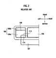
- the air conditioner case 103 is formed with a defroster opening 104 which introduces conditioned air to be discharged toward a front window glass of the vehicle, a front seat center vent opening 105 (shown in Fig.
- a passage distance from the back seat vent opening 107 to the back seat vent blowout opening (not shown) is longer than each passage distance of vent on the front seat, and air blowing resistance on the side of the back seat vent is high. Therefore, a volume of air which is in proportion to an area of the opening like the front seat vent cannot be obtained.
- the opening area of the back seat vent opening 107 is merely widened, the air conditioner is increased in size.
- the back seat auxiliary vent opening 114 is formed in the front seat side vent opening 106, and the volume of air being discharged from the back seat vent blowout opening (not shown) is increased without merely increasing the opening area of the back seat vent opening 107 in the longitudinal direction or widthwise direction of the vehicle.
- the front seat center vent opening 105 and the front seat side vent opening 106 are disposed in a side-by-side configuration, and the back seat vent opening 107 is disposed around this side-by-side configuration. Therefore, opening areas of the front seat center vent opening 105 and the front seat side vent opening 106 are relatively reduced.
- back seat vent opening 107 is disposed at arbitrary location where an air mix area is desired, conditioned air into which air is not sufficiently mixed is taken in.
- said objective is solved by a vehicular air conditioner having the features of independent claim 1.
- a preferred embodiment is laid down in the dependent claim.
- the front seat vent opening can be disposed over the entire region of a position into which cold air substantially straightly enters and thus, an opening area of the front seat vent opening can be sufficiently taken. Since the foot opening is formed in a position where mixed conditioned air can be taken in, sufficiently mixed conditioned air is introduced also into the back seat vent opening formed near the foot opening. From the above reasons, sufficiently mixed conditioned air can be taken into the back seat vent opening without reducing the airblowing volume into the front seat vent opening.
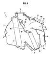
- an air sending passage 4 is formed in an air conditioner case 3 of the air conditioner unit 2.
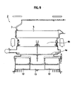
- An evaporator 5, an air mix door 6 (shown in Fig. 7 and the like) and a heater core 7 are disposed in the air sending passage 4 from an upstream side in the air blowing direction.
- the defroster opening 10 is disposed above the air mix area ME.
- the defroster opening 10 introduces conditioned air to be discharged toward the front window glass of the vehicle, and is connected to a blowout opening (not shown) of the defroster disposed on an upper surface of an instrument panel.
- the defroster door 20 is in the fully-opened position, the vent foot switching door 21 is in the vent fully-closed position, and the foot door 22 and the back seat vent door 23 are in the foot fully-closedposition and the back seat vent fully-closed position.
- Conditioned air into which air is mixed in the air mix area ME is introduced into the defroster opening 10 and discharged into the passenger room from the defroster blowout opening (not shown) . Since the portions of the side vent openings 11b and 11b are not closed even in the vent fully-closed position of the vent foot switching door 21, a portion of the conditioned air is discharged into the passenger room from the side vent blowout opening (not shown).
- the defroster door 20 is in the fully-closed position, the vent foot switching door 21 is in the vent fully-closed position, and the foot door 22 and the back seat vent door 23 is in the foot fully-opened position and the back seat vent fully-opened position.
- Conditioned air into which air is mixed in the air mix area ME is introduced into the foot opening 12 and the back seat vent opening 13.
- the conditioned air introduced into the foot opening 12 is discharged toward the front seat through the foot passage 14 and the like and into the passenger room from the back seat foot blowout opening (not shown).
- Conditioned air introduced into the back seat vent opening 13 is discharged into the passenger room from the back seat vent blowout opening (not shown) through the back seat vent passage 17. Since portions of the side vent openings 11b and 11b are not closed even in the vent fully-closed position of the vent foot switching door 21, a portion of the conditioned air is discharged into the passenger room from the side vent blowout opening.
- the defroster door 20 is in the fully-closed position
- the vent foot switching door 21 is in the foot fully-closed position
- the foot door 22 and the back seat vent door 23 are in the foot fully-opened position and the back seat vent fully-opened position.
- the conditioned air is introduced into the front seat vent opening 11 and the back seat vent opening 13.
- Conditioned air introduced into the front seat vent opening is discharged into the passenger room from the front seat center vent blowout opening (not shown) and the front seat side vent blowout opening (not shown) .
- Conditioned air introduced into the back seat vent opening 13 is discharged into the passenger room from the back seat vent blowout opening (not shown) through the back seat vent passage 17 and the like.
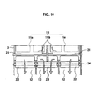
- the back seat vent opening 13 is provided near the foot openings 12, and the back seat vent door 23 which opens and closes the back seat vent opening 13 and the foot doors 22 which open and close the foot openings 12 are provided downstream from the vent foot switching door 21. Therefore, the front seat vent opening 11 can be disposed over the entire region of a position into which cold air substantially straightly enters and thus, the opening area of the front seat vent opening 11 can be secured sufficiently. Since the foot opening 12 is formed in a position where mixed conditioned air can be sufficiently taken in, sufficiently mixed conditioned air is introduced also into the back seat vent opening 13 formed near the foot opening 12. From the above reasons, sufficiently mixed conditioned air can be taken into the back seat vent opening 13 without reducing the air blowing volume into the front seat vent opening 11.
- the back seat vent door 23 and the foot doors 22 are provided downstream from the vent foot switching door 21, air mixing degree of the doors 22 and 23 is not deteriorated. That is, if the back seat vent door 23 and the foot doors 22 are provided at substantially the same position as the vent foot switching door 21, flow of conditioned air from the air mix area ME to each opening is influenced by the position of the door, and there is an adverse possibility that the air mixing degree is deteriorated. In this embodiment, however, since the back seat vent door 23 and the foot doors 22 are disposed in the back seat vent passage 17 and the foot passage 14, the flow of conditioned air is not influenced by the position of the door, and the air mixing degree is not deteriorated.
- the back seat vent door 23 and the foot doors 22 are opened, closed and moved integrally. That is, in the air-blowing modes other than the defroster mode, the back seat vent opening 13 is in the opened position to take air in, but if desired control is performed for the foot doors 22, the back seat vent door 23 is brought into the predetermined position described above. Therefore, it is not necessary to control the back seat vent door 23 independently.
Landscapes
- Physics & Mathematics (AREA)
- Thermal Sciences (AREA)
- Engineering & Computer Science (AREA)
- Mechanical Engineering (AREA)
- Air-Conditioning For Vehicles (AREA)
Claims (2)
- Fahrzeugklimaanlage, in der eine Defrosteröffnung (10), eine Vordersitz- Lüftungsöffnung (11) und eine Fußöffnung (12) an Orten, gegenüberliegend zu einem Luftmischbereich (ME) in einem Klimaanlagengehäuse (3), vorgesehen sind, wobei eine Defrosterklappe (20), die die Entfrosteröffnung (10) öffnet oder schließt, und eine Fußlüftungs- Schaltklappe (21), die wahlweise die Fußöffnung (12) und die Vordersitz- Lüftungsöffnung (11) öffnet oder schließt, vorgesehen ist, wobei eine Rücksitz- Lüftungsöffnung (13) nahe der Fußöffnung (12) vorgesehen ist, dadurch gekennzeichnet, dass die Rücksitz- Lüftungsöffnung (13) zwischen einem Paar von linken und rechten Fußöffnungen (12) und einer Rücksitz- Lüftungsklappe (23), die die Rücksitz- Lüftungsöffnung (13) öffnet oder schließt, vorgesehen ist und Fußklappen (22), die die Fußöffnungen (12) öffnen oder schließen, stromab von der Fußlüftungs- Schaltklappe (21) vorgesehen sind.
- Fahrzeugklimaanlage nach Anspruch 1, dadurch gekennzeichnet, dass die Rücksitz- Lüftungsklappe (23) und die Fußklappen (22) einstückig geöffnet, geschlossen und bewegt werden.
Applications Claiming Priority (1)
| Application Number | Priority Date | Filing Date | Title |
|---|---|---|---|
| JP2005331905A JP5189732B2 (ja) | 2005-11-16 | 2005-11-16 | 自動車用空気調和装置 |
Publications (2)
| Publication Number | Publication Date |
|---|---|
| EP1787836A1 EP1787836A1 (de) | 2007-05-23 |
| EP1787836B1 true EP1787836B1 (de) | 2009-08-05 |
Family
ID=37685189
Family Applications (1)
| Application Number | Title | Priority Date | Filing Date |
|---|---|---|---|
| EP06023667A Ceased EP1787836B1 (de) | 2005-11-16 | 2006-11-14 | Fahrzeug-Klimaanlage |
Country Status (5)
| Country | Link |
|---|---|
| US (1) | US7905278B2 (de) |
| EP (1) | EP1787836B1 (de) |
| JP (1) | JP5189732B2 (de) |
| CN (1) | CN100448708C (de) |
| DE (1) | DE602006008248D1 (de) |
Families Citing this family (22)
| Publication number | Priority date | Publication date | Assignee | Title |
|---|---|---|---|---|
| US7380586B2 (en) | 2004-05-10 | 2008-06-03 | Bsst Llc | Climate control system for hybrid vehicles using thermoelectric devices |
| US7743614B2 (en) | 2005-04-08 | 2010-06-29 | Bsst Llc | Thermoelectric-based heating and cooling system |
| US9090143B2 (en) | 2006-10-27 | 2015-07-28 | Calsonic Kansei Corporation | Vehicle air conditioner foot and rear vent door arrangement |
| CN104990301B (zh) | 2007-05-25 | 2019-04-16 | 詹思姆公司 | 分配式热电加热和冷却的系统和方法 |
| US9555686B2 (en) | 2008-10-23 | 2017-01-31 | Gentherm Incorporated | Temperature control systems with thermoelectric devices |
| US9447994B2 (en) | 2008-10-23 | 2016-09-20 | Gentherm Incorporated | Temperature control systems with thermoelectric devices |
| WO2010135363A2 (en) | 2009-05-18 | 2010-11-25 | Bsst Llc | Temperature control system with thermoelectric device |
| US10029536B2 (en) * | 2009-05-29 | 2018-07-24 | Honda Motor Co., Ltd. | Integrated front and rear HVAC system |
| US8408980B2 (en) * | 2009-07-10 | 2013-04-02 | Keihin Corporation | Vehicular air conditioning apparatus |
| JP2012040960A (ja) * | 2010-08-19 | 2012-03-01 | Keihin Corp | 車両用空気調和システム |
| EP2567841B1 (de) * | 2011-09-09 | 2019-01-02 | Hanon Systems | Klimaanlage für ein Fahrzeug |
| KR20130064393A (ko) * | 2011-12-08 | 2013-06-18 | 현대자동차주식회사 | 차량용 공조장치의 공기토출 시스템 |
| US8893517B2 (en) * | 2012-08-27 | 2014-11-25 | Ford Global Technologies, Llc | Vehicle air handling system |
| US9694652B2 (en) * | 2013-01-08 | 2017-07-04 | Doowon Climate Control Co., Ltd | Vehicle rear console duct air flow |
| KR20170095952A (ko) | 2014-12-19 | 2017-08-23 | 젠썸 인코포레이티드 | 차량 영역을 위한 열적 조화 시스템 및 방법 |
| US10625566B2 (en) | 2015-10-14 | 2020-04-21 | Gentherm Incorporated | Systems and methods for controlling thermal conditioning of vehicle regions |
| JP2018043192A (ja) * | 2016-09-14 | 2018-03-22 | カルソニックカンセイ株式会社 | 空気浄化装置 |
| CN106828014B (zh) * | 2017-01-03 | 2019-06-18 | 北京汽车股份有限公司 | 用于车辆的空调系统及具有其的车辆 |
| US10882378B2 (en) * | 2017-08-18 | 2021-01-05 | Zhejiang CFMOTO Power Co., Ltd. | ATV air heat exchanger with mounting structure and linkage |
| KR102536615B1 (ko) * | 2018-06-11 | 2023-05-25 | 한온시스템 주식회사 | 차량용 공조장치 |
| WO2021145712A1 (ko) * | 2020-01-17 | 2021-07-22 | 한온시스템 주식회사 | 차량용 공조장치 |
| DE102021113120B3 (de) * | 2021-05-20 | 2022-06-02 | Audi Aktiengesellschaft | Ionisationsvorrichtung und Luftführungsanordnung für ein Fahrzeug |
Family Cites Families (38)
| Publication number | Priority date | Publication date | Assignee | Title |
|---|---|---|---|---|
| JPS60259517A (ja) * | 1984-06-04 | 1985-12-21 | Diesel Kiki Co Ltd | 自動車用空気調和装置 |
| JPS63154303U (de) * | 1987-03-31 | 1988-10-11 | ||
| EP0397997B1 (de) * | 1989-05-19 | 1992-12-30 | Siemens Aktiengesellschaft | Heiz- und Klimagerät für ein Kraftfahrzeug |
| JPH0754008Y2 (ja) * | 1989-07-20 | 1995-12-13 | 日産自動車株式会社 | 自動車用ヒーターユニット |
| DE59300637D1 (de) * | 1993-12-20 | 1995-10-26 | Siemens Ag | Heiz- bzw. Klimagerät, insbesondere zum Einbau in ein Kraftfahrzeug. |
| JP3422136B2 (ja) * | 1995-07-06 | 2003-06-30 | 株式会社デンソー | 自動車用空調装置 |
| US5673964A (en) * | 1995-08-04 | 1997-10-07 | Ford Motor Company | Integral center-mounted airhandling system with integral instrument panel air-conditioning duct and structural beam |
| US5687790A (en) * | 1995-12-26 | 1997-11-18 | Chrysler Corporation | Heater, ventilation and air conditioning assembly for a motor vehicle |
| JP3713780B2 (ja) * | 1995-12-26 | 2005-11-09 | 株式会社デンソー | 空調装置 |
| JPH09226350A (ja) * | 1996-02-28 | 1997-09-02 | Calsonic Corp | 車両用空気調和装置のヒータユニット |
| JP3582219B2 (ja) * | 1996-04-01 | 2004-10-27 | 株式会社デンソー | 自動車用空調装置 |
| KR100294482B1 (ko) * | 1996-07-27 | 2001-10-24 | 신영주 | 공기조화장치의케이스와이를이용한공기조화장치 |
| JPH10236137A (ja) * | 1996-12-24 | 1998-09-08 | Denso Corp | 車両用空調装置 |
| JPH1148751A (ja) * | 1997-07-31 | 1999-02-23 | Mitsubishi Heavy Ind Ltd | 車両用空調装置 |
| DE19804287C5 (de) * | 1998-02-04 | 2004-02-19 | Daimlerchrysler Ag | Klimaanlage für Fahrzeuge |
| JP4048587B2 (ja) * | 1998-02-19 | 2008-02-20 | 株式会社デンソー | 車両用空調装置 |
| JP4016496B2 (ja) * | 1998-08-28 | 2007-12-05 | 株式会社デンソー | 車両用空調装置 |
| JP2000127742A (ja) * | 1998-10-22 | 2000-05-09 | Zexel Corp | 車両用空調装置 |
| FR2787392B1 (fr) * | 1998-12-21 | 2002-01-11 | Valeo Climatisation | Dispositif de chauffage-climatisaiton d'encombrement reduit pour vehicule automobile |
| JP2000238526A (ja) * | 1999-02-23 | 2000-09-05 | Denso Corp | 車両用空調装置 |
| DE19922324C1 (de) * | 1999-05-14 | 2000-10-19 | Daimler Chrysler Ag | Heizungs- oder Klimaanlage für eine Fahrgastzelle eines Fahrzeugs |
| JP4196492B2 (ja) * | 1999-08-17 | 2008-12-17 | 株式会社デンソー | 車両用空調装置 |
| JP4061793B2 (ja) * | 1999-11-11 | 2008-03-19 | 株式会社デンソー | 車両用空調装置 |
| JP4253960B2 (ja) * | 1999-11-18 | 2009-04-15 | 株式会社デンソー | 車両用空調装置 |
| US6415851B1 (en) * | 1999-12-21 | 2002-07-09 | Visteon Global Technologies, Inc. | Multi-zone temperature control system for HVAC air-handling assembly |
| FR2804377B1 (fr) * | 2000-01-28 | 2002-06-14 | Valeo Climatisation | Installation de climatisation de vehicule a traitement separe pour l'arriere de l'habitacle |
| JP2002046451A (ja) * | 2000-08-01 | 2002-02-12 | Denso Corp | 車両用空調装置 |
| DE10037384B4 (de) * | 2000-08-01 | 2013-04-04 | Behr Gmbh & Co. Kg | Heizungs- und Klimaanlage für ein Kraftfahrzeug |
| US6736190B2 (en) * | 2001-04-03 | 2004-05-18 | Denso Corporation | Vehicle air conditioner |
| CA2394689A1 (en) * | 2001-07-25 | 2003-01-25 | Nobuya Nakagawa | Air-conditioning system for a vehicle |
| JP4671566B2 (ja) * | 2001-09-18 | 2011-04-20 | サンデン株式会社 | 自動車用空調装置 |
| JP3960020B2 (ja) * | 2001-11-22 | 2007-08-15 | 株式会社デンソー | 車両用空調装置 |
| US6769978B2 (en) * | 2001-12-21 | 2004-08-03 | Modine Manufacturing Company | Method and apparatus for controlling airflow in a vehicular HVAC system |
| US6772833B2 (en) * | 2002-07-23 | 2004-08-10 | Visteon Global Technologies, Inc. | HVAC system with modular inserts |
| JP4082121B2 (ja) * | 2002-07-26 | 2008-04-30 | 株式会社デンソー | 車両用空調装置 |
| JP2004098964A (ja) * | 2002-09-12 | 2004-04-02 | Denso Corp | 車両用空調装置 |
| JP3931818B2 (ja) * | 2003-02-13 | 2007-06-20 | 株式会社デンソー | 車両用空調装置 |
| EP1685990B1 (de) * | 2005-02-01 | 2009-08-26 | Halla Climate Control Corporation | Fahrzeugklimaanlage |
-
2005
- 2005-11-16 JP JP2005331905A patent/JP5189732B2/ja not_active Expired - Lifetime
-
2006
- 2006-11-14 DE DE602006008248T patent/DE602006008248D1/de active Active
- 2006-11-14 EP EP06023667A patent/EP1787836B1/de not_active Ceased
- 2006-11-15 US US11/599,594 patent/US7905278B2/en active Active
- 2006-11-16 CN CNB2006101457363A patent/CN100448708C/zh not_active Expired - Fee Related
Also Published As
| Publication number | Publication date |
|---|---|
| JP5189732B2 (ja) | 2013-04-24 |
| US7905278B2 (en) | 2011-03-15 |
| CN100448708C (zh) | 2009-01-07 |
| JP2007137189A (ja) | 2007-06-07 |
| US20070107892A1 (en) | 2007-05-17 |
| CN1966290A (zh) | 2007-05-23 |
| EP1787836A1 (de) | 2007-05-23 |
| DE602006008248D1 (de) | 2009-09-17 |
Similar Documents
| Publication | Publication Date | Title |
|---|---|---|
| US7905278B2 (en) | Vehicular air conditioner | |
| US20040089007A1 (en) | Ceiling air-blowing device for a vehicle air conditioner | |
| JP4196492B2 (ja) | 車両用空調装置 | |
| JPH11235916A (ja) | 車両用空調装置 | |
| US20070266726A1 (en) | Air-conditioning unit and air-conditioning apparatus | |
| JP4016496B2 (ja) | 車両用空調装置 | |
| JP2015164837A (ja) | 車両用空気調和装置 | |
| US5890651A (en) | Air conditioning apparatus for vehicle | |
| JPH09267620A (ja) | 自動車用空調装置 | |
| JP2000255247A (ja) | 車両用空調装置 | |
| CN110562004A (zh) | 车辆用空调装置 | |
| JP2001191782A (ja) | 車両用空調装置 | |
| JPH11222021A (ja) | 車両用空調装置 | |
| JP3972492B2 (ja) | 車両用空調装置 | |
| JP4602839B2 (ja) | 自動車用空気調和装置 | |
| JP2003039930A (ja) | 車両用空調装置 | |
| JP3798897B2 (ja) | 自動車用空気調和装置 | |
| JP2008087576A (ja) | 車両用空調装置 | |
| KR20120019118A (ko) | 차량용 공조장치 | |
| JP2001277838A (ja) | 車両用空調装置 | |
| KR102192849B1 (ko) | 차량용 공조장치 | |
| JP2001010329A (ja) | 車両用空調装置 | |
| KR20010109987A (ko) | 자동차용 공기조화장치 | |
| JPH05319216A (ja) | 車両用空調装置 | |
| JP2003054242A (ja) | 車両用空調ユニット |
Legal Events
| Date | Code | Title | Description |
|---|---|---|---|
| PUAI | Public reference made under article 153(3) epc to a published international application that has entered the european phase |
Free format text: ORIGINAL CODE: 0009012 |
|
| AK | Designated contracting states |
Kind code of ref document: A1 Designated state(s): AT BE BG CH CY CZ DE DK EE ES FI FR GB GR HU IE IS IT LI LT LU LV MC NL PL PT RO SE SI SK TR |
|
| AX | Request for extension of the european patent |
Extension state: AL BA HR MK YU |
|
| 17P | Request for examination filed |
Effective date: 20071012 |
|
| 17Q | First examination report despatched |
Effective date: 20071107 |
|
| AKX | Designation fees paid |
Designated state(s): DE FR GB |
|
| GRAP | Despatch of communication of intention to grant a patent |
Free format text: ORIGINAL CODE: EPIDOSNIGR1 |
|
| RIN1 | Information on inventor provided before grant (corrected) |
Inventor name: SATO, SEIJIC/O CALSONIC KANSEI CORPORATION Inventor name: TSUKUDA, RYUJIC/O CALSONIC KANSEI CORPORATION |
|
| GRAS | Grant fee paid |
Free format text: ORIGINAL CODE: EPIDOSNIGR3 |
|
| GRAA | (expected) grant |
Free format text: ORIGINAL CODE: 0009210 |
|
| AK | Designated contracting states |
Kind code of ref document: B1 Designated state(s): DE FR GB |
|
| REG | Reference to a national code |
Ref country code: GB Ref legal event code: FG4D |
|
| REF | Corresponds to: |
Ref document number: 602006008248 Country of ref document: DE Date of ref document: 20090917 Kind code of ref document: P |
|
| PLBE | No opposition filed within time limit |
Free format text: ORIGINAL CODE: 0009261 |
|
| STAA | Information on the status of an ep patent application or granted ep patent |
Free format text: STATUS: NO OPPOSITION FILED WITHIN TIME LIMIT |
|
| 26N | No opposition filed |
Effective date: 20100507 |
|
| REG | Reference to a national code |
Ref country code: FR Ref legal event code: PLFP Year of fee payment: 10 |
|
| REG | Reference to a national code |
Ref country code: FR Ref legal event code: PLFP Year of fee payment: 11 |
|
| REG | Reference to a national code |
Ref country code: FR Ref legal event code: PLFP Year of fee payment: 12 |
|
| REG | Reference to a national code |
Ref country code: FR Ref legal event code: PLFP Year of fee payment: 13 |
|
| REG | Reference to a national code |
Ref country code: DE Ref legal event code: R081 Ref document number: 602006008248 Country of ref document: DE Owner name: HIGHLY MARELLI JAPAN CORPORATION, JP Free format text: FORMER OWNER: CALSONIC KANSEI CORP., TOKIO/TOKYO, JP Ref country code: DE Ref legal event code: R082 Ref document number: 602006008248 Country of ref document: DE Representative=s name: GRUENECKER PATENT- UND RECHTSANWAELTE PARTG MB, DE Ref country code: DE Ref legal event code: R081 Ref document number: 602006008248 Country of ref document: DE Owner name: MARELLI CABIN COMFORT JAPAN CORP., JP Free format text: FORMER OWNER: CALSONIC KANSEI CORP., TOKIO/TOKYO, JP |
|
| REG | Reference to a national code |
Ref country code: GB Ref legal event code: 732E Free format text: REGISTERED BETWEEN 20210121 AND 20210127 |
|
| REG | Reference to a national code |
Ref country code: DE Ref legal event code: R081 Ref document number: 602006008248 Country of ref document: DE Owner name: HIGHLY MARELLI JAPAN CORPORATION, JP Free format text: FORMER OWNER: MARELLI CABIN COMFORT JAPAN CORP., SAITAMA-SHI, JP |
|
| PGFP | Annual fee paid to national office [announced via postgrant information from national office to epo] |
Ref country code: GB Payment date: 20231123 Year of fee payment: 18 |
|
| PGFP | Annual fee paid to national office [announced via postgrant information from national office to epo] |
Ref country code: FR Payment date: 20231120 Year of fee payment: 18 Ref country code: DE Payment date: 20231121 Year of fee payment: 18 |
|
| REG | Reference to a national code |
Ref country code: DE Ref legal event code: R119 Ref document number: 602006008248 Country of ref document: DE |
|
| GBPC | Gb: european patent ceased through non-payment of renewal fee |
Effective date: 20241114 |
|
| PG25 | Lapsed in a contracting state [announced via postgrant information from national office to epo] |
Ref country code: DE Free format text: LAPSE BECAUSE OF NON-PAYMENT OF DUE FEES Effective date: 20250603 |
|
| PG25 | Lapsed in a contracting state [announced via postgrant information from national office to epo] |
Ref country code: GB Free format text: LAPSE BECAUSE OF NON-PAYMENT OF DUE FEES Effective date: 20241114 |
|
| PG25 | Lapsed in a contracting state [announced via postgrant information from national office to epo] |
Ref country code: FR Free format text: LAPSE BECAUSE OF NON-PAYMENT OF DUE FEES Effective date: 20241130 |