EP1787927A2 - Verfahren und Vorrichtung zur Steuerung der vereinzelten Zufuhr von Bogen - Google Patents
Verfahren und Vorrichtung zur Steuerung der vereinzelten Zufuhr von Bogen Download PDFInfo
- Publication number
- EP1787927A2 EP1787927A2 EP06023401A EP06023401A EP1787927A2 EP 1787927 A2 EP1787927 A2 EP 1787927A2 EP 06023401 A EP06023401 A EP 06023401A EP 06023401 A EP06023401 A EP 06023401A EP 1787927 A2 EP1787927 A2 EP 1787927A2
- Authority
- EP
- European Patent Office
- Prior art keywords
- sheet
- suction head
- stack
- sheet feeder
- distance
- Prior art date
- Legal status (The legal status is an assumption and is not a legal conclusion. Google has not performed a legal analysis and makes no representation as to the accuracy of the status listed.)
- Granted
Links
Images
Classifications
-
- B—PERFORMING OPERATIONS; TRANSPORTING
- B65—CONVEYING; PACKING; STORING; HANDLING THIN OR FILAMENTARY MATERIAL
- B65H—HANDLING THIN OR FILAMENTARY MATERIAL, e.g. SHEETS, WEBS, CABLES
- B65H3/00—Separating articles from piles
- B65H3/08—Separating articles from piles using pneumatic force
- B65H3/0808—Suction grippers
- B65H3/0816—Suction grippers separating from the top of pile
- B65H3/0825—Suction grippers separating from the top of pile and acting on the rear part of the articles relatively to the final separating direction
-
- B—PERFORMING OPERATIONS; TRANSPORTING
- B65—CONVEYING; PACKING; STORING; HANDLING THIN OR FILAMENTARY MATERIAL
- B65H—HANDLING THIN OR FILAMENTARY MATERIAL, e.g. SHEETS, WEBS, CABLES
- B65H1/00—Supports or magazines for piles from which articles are to be separated
- B65H1/08—Supports or magazines for piles from which articles are to be separated with means for advancing the articles to present the articles to the separating device
- B65H1/18—Supports or magazines for piles from which articles are to be separated with means for advancing the articles to present the articles to the separating device controlled by height of pile
-
- B—PERFORMING OPERATIONS; TRANSPORTING
- B65—CONVEYING; PACKING; STORING; HANDLING THIN OR FILAMENTARY MATERIAL
- B65H—HANDLING THIN OR FILAMENTARY MATERIAL, e.g. SHEETS, WEBS, CABLES
- B65H7/00—Controlling article feeding, separating, pile-advancing, or associated apparatus, to take account of incorrect feeding, absence of articles, or presence of faulty articles
- B65H7/18—Modifying or stopping actuation of separators
-
- B—PERFORMING OPERATIONS; TRANSPORTING
- B65—CONVEYING; PACKING; STORING; HANDLING THIN OR FILAMENTARY MATERIAL
- B65H—HANDLING THIN OR FILAMENTARY MATERIAL, e.g. SHEETS, WEBS, CABLES
- B65H2407/00—Means not provided for in groups B65H2220/00 – B65H2406/00 specially adapted for particular purposes
- B65H2407/10—Safety means, e.g. for preventing injuries or illegal operations
-
- B—PERFORMING OPERATIONS; TRANSPORTING
- B65—CONVEYING; PACKING; STORING; HANDLING THIN OR FILAMENTARY MATERIAL
- B65H—HANDLING THIN OR FILAMENTARY MATERIAL, e.g. SHEETS, WEBS, CABLES
- B65H2511/00—Dimensions; Position; Numbers; Identification; Occurrences
- B65H2511/20—Location in space
- B65H2511/22—Distance
-
- B—PERFORMING OPERATIONS; TRANSPORTING
- B65—CONVEYING; PACKING; STORING; HANDLING THIN OR FILAMENTARY MATERIAL
- B65H—HANDLING THIN OR FILAMENTARY MATERIAL, e.g. SHEETS, WEBS, CABLES
- B65H2515/00—Physical entities not provided for in groups B65H2511/00 or B65H2513/00
- B65H2515/30—Forces; Stresses
- B65H2515/34—Pressure, e.g. fluid pressure
-
- B—PERFORMING OPERATIONS; TRANSPORTING
- B65—CONVEYING; PACKING; STORING; HANDLING THIN OR FILAMENTARY MATERIAL
- B65H—HANDLING THIN OR FILAMENTARY MATERIAL, e.g. SHEETS, WEBS, CABLES
- B65H2553/00—Sensing or detecting means
- B65H2553/40—Sensing or detecting means using optical, e.g. photographic, elements
- B65H2553/41—Photoelectric detectors
Definitions
- the invention relates to a method for controlling the isolated supply of sheets from a sheet feeder to a sheet-processing machine, with a pile support plate of the sheet feeder on which a stack of sheets can be placed and which is vertically adjustable by a lifting device and arranged with one above the stack of sheets Suction head of the sheet feeder, which has a vertically movable drivable separating suction and / or horizontally movable in and against the conveying direction drag sucker, wherein the stack support plate is einregelbar to a certain height distance between the uppermost sheet of the sheet stack and the suction head, which is detectable by a scanning device , from which a corresponding distance signal can be supplied on receipt of the determined height distance of a control unit, of which the operating mode of the suction head is controlled.
- the object of the invention is to provide a method of the type mentioned above and a sheet feeder for carrying out the method, are avoided by the damage of reaching in the path of movement of vacuum cleaner and / or tractor sucker parts.
- This object is achieved in a method of the type mentioned above in that is switched inactive when not present the specific distance signal from the control unit of the suction head.
- the stacking plate is raised so far that only a small height distance between the uppermost sheet of the sheet stack and the suction head is present. This distance is so small that objects, especially human hands can not be brought between the top sheet of the sheet stack and the suction head. This is without additional components alone by locking the operation at not taken certain height distance between the top sheet and the suction head between pinching and damaging parts, in particular of body parts of a person prevented.
- the object is in a sheet feeder with a pile support plate on which a stack of sheets can be placed and which is vertically adjustable by a lifting device and arranged above the sheet stack suction head, a vertically movable drivable separating sucker and / or a horizontal in and against
- the conveying direction has movably drivable Schleppsauger, wherein the stacking plate einregelbar to a certain height distance between the uppermost sheet of the sheet stack and the suction head, which is detectable by a scanning device, from which a corresponding distance signal when taking the certain height distance of a control unit can be fed, from the the operating mode of the suction head is controlled by the fact that the scanning device is arranged in the region of the suction head.
- the scanning device may be a presser foot, through which the particular height distance of the rear end of the sheet stack in the conveying direction can be scanned to the suction head.
- the scanning device is a non-contact the specific height distance of the sheet stack to the suction head detecting distance sensor, wherein the distance sensor is preferably an optical distance sensor.
- the distance sensor can also be arranged on the suction head or on a machine frame of the sheet feeder.
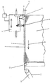
- the sheet feeder shown in the figure has a stack support plate, not shown, on which a sheet stack 1 rests.
- the stack carrier plate is vertically adjustable.
- the stack support plate lowered into its lowest position and a new stack of sheets are placed on it.
- the stack support plate is raised again until the uppermost sheet 2 of the sheet stack 1 is a certain height distance 3 to a mounted on a sheet stack 1 arranged suction head 4 of the sheet feeder optical distance sensor 5.
- the suction head 4 has a separating sucker 6, is detected by the clock in the process of a sheet, not shown, by lowering the Trennsaugers 6 on the sheet stack 1 of the uppermost sheet 2. Subsequently, the separating sucker 6 moves upward again, thereby raising the detected sheet 7 in the position shown.
- the sheet stack 7 is detected by a drag sucker 8 of the suction head 4 and moved under release of the vacuum cleaner 6 horizontally in the sheet conveying direction 9, so that the sheet conveying direction 9 front end of the sheet 7 reaches a suction belt table 10.
- the Schleppsauger 8 moves horizontally from the position shown in the sheet conveying direction 9 rear position in a sheet conveying direction 9 front position. If the sheet feed direction 9 front position is reached, in which the front end portion of the sheet 7 passes through a roller 13 for resting on the Saugb selected illness 10 and is detected by the suction belts 11, the sheet 7 is released from the Schleppsauger 8.
- the Schleppsauger 8 then moves back to its rear position.
- a control unit 12 which controls both the working operation of the sheet feeder and the suction head 4, and in deviation from a predetermined height distance value within a tolerance range controls the lifting device and lift the stack support plate so that the top sheet 2 again occupies the certain height distance 3.
- control unit 12 If a distance outside the tolerance range to the uppermost sheet 7 is detected by the distance sensor 5 and a corresponding signal is fed to the control unit 12, then the control unit 12 deactivates the suction head 4.
Landscapes
- Engineering & Computer Science (AREA)
- Mechanical Engineering (AREA)
- Sheets, Magazines, And Separation Thereof (AREA)
Abstract
Description
- Die Erfindung bezieht sich auf ein Verfahren zur Steuerung der vereinzelten Zufuhr von Bogen von einem Bogenanleger zu einer Bogen verarbeitenden Maschine, mit einer Stapeltragplatte des Bogenanlegers, auf der ein Bogenstapel auflegbar ist und die durch eine Hubvorrichtung vertikal verstellbar ist sowie mit einem über dem Bogenstapel angeordneten Saugkopf des Bogenanlegers, der einen vertikal bewegbar antreibbaren Trennsauger und/oder einen horizontal in und entgegen der Förderrichtung bewegbar antreibbaren Schleppsauger aufweist, wobei die Stapeltragplatte auf einen bestimmten Höhenabstand zwischen dem obersten Bogen des Bogenstapels und dem Saugkopf einregelbar ist, der durch eine Abtasteinrichtung erfaßbar ist, von der ein entsprechendes Abstandssignal bei Einnahme des bestimmten Höhenabstands einer Steuereinheit zuführbar ist, von der der Arbeitsbetrieb des Saugkopfs gesteuert wird.
- Bei derartigen Bogenanlegern erfolgt die Bewegung der Trennsauger und der Schleppsauger mit einer erheblichen Geschwindigkeit und einer erheblichen Verstellkraft. Befinden sich Gegenstände in dem Verstellweg, werden diese daher von den Trennsaugern und den Schleppsaugern mit hohen Kräften beaufschlagt.
- Dadurch kann es zu einem Einklemmen dieser Gegenstände zwischen den Trennsaugern oder den Schleppsaugern und einem feststehenden Teil des Saugkopfs kommen, was zu Beschädigungen dieser Teile führen kann.
- Besonders problematisch ist es, wenn es sich bei den in dem Bewegungsweg der Trennsauger oder Schleppsauger gelangenden Teile um Körperteile eines Menschen wie z.B. des Hände handelt, an denen es zu schweren Verletzungen kommen kann.
- Aufgabe der Erfindung ist es ein Verfahren der eingangs genannten Art sowie einen Bogenleger zur Durchführung des Verfahrens zu schaffen, durch die Beschädigungen von in den Bewegungsweg von Trennsaugern und/oder Schleppsaugern gelangenden Teilen vermieden werden.
- Diese Aufgabe wird bei einem Verfahren der eingangs genannten Art dadurch gelöst, daß bei Nichtvorlage des bestimmten Abstandssignals von der Steuereinheit der Saugkopf inaktiv geschaltet wird.
- Im Arbeitsbetrieb des Saugkopfes ist die Stapelplatte soweit hochgefahren, daß nur ein geringer Höhenabstand zwischen dem obersten Bogen des Bogenstapels und dem Saugkopf vorhanden ist. Dieser Abstand ist so gering, daß Gegenstände, insbesondere Hände eines Menschen nicht zwischen den obersten Bogen des Bogenstapels und den Saugkopf gebracht werden können. Damit wird ohne zusätzliche Bauteile allein durch das Sperren des Betriebes bei nicht eingenommenem bestimmten Höhenabstand zwischen dem obersten Bogen und dem Saugkopf ein dazwischen Einklemmen und Beschädigen von Teilen, insbesondere von Körperteilen eines Menschen verhindert.
- Da keine zusätzlichen Schutzmaßnahmen erforderlich sind, müssen diese bei Wartungs- und Reparaturarbeiten auch nicht demontiert und wieder montiert werden.
- Damit wird die Ausfallzeit des Bogenanlegers für Wartungs- und Reparaturarbeiten erheblich reduziert.
- Die Aufgabe wird bei einem Bogenanleger mit einer Stapeltragplatte, auf der ein Bogenstapel auflegbar ist und die durch eine Hubvorrichtung vertikal verstellbar ist sowie mit einem über dem Bogenstapel angeordneten Saugkopf, der einen vertikal bewegbar antreibbaren Trennsauger und/oder einen horizontal in und entgegen der Förderrichtung bewegbar antreibbaren Schleppsauger aufweist, wobei die Stapelplatte auf einen bestimmten Höhenabstand zwischen dem obersten Bogen des Bogenstapels und dem Saugkopf einregelbar ist, der durch eine Abtasteinrichtung erfaßbar ist, von der ein entsprechendes Abstandssignal bei Einnahme des bestimmten Höhenabstands einer Steuereinheit zuführbar ist, von der der Arbeitsbetrieb des Saugkopfs steuerbar ist dadurch gelöst, daß die Abtasteinrichtung im Bereich des Saugkopfes angeordnet ist.
- Damit erfolgt eine Erfassung des Höhenabstandes zwischen dem obersten Bogen an der dafür optimalen Stelle.
- Dabei kann die Abtasteinrichtung ein Drückerfuß sein, durch den der bestimmte Höhenabstand des in Förderrichtung hinteren Endes des Bogenstapels-zum Saugkopf abtastbar ist.
- Eine andere Möglichkeit besteht darin, daß die Abtasteinrichtung ein berührungslos den bestimmten Höhenabstand des Bogenstapels zum Saugkopf erfassender Abstandssensor ist, wobei der der Abstandssensor vorzugsweise ein optischer Abstandssensor ist.
- Der Abstandssensor kann aber auch an dem Saugkopf oder an einem Maschinengestell des Bogenanlegers angeordnet sein.
- Ein Ausführungsbeispiel der Erfindung ist in der Zeichnung dargestellt und wird im folgenden näher beschrieben. Die einzige Figur der Zeichnung zeigt eine Seitenansicht eines Bogenanlegers.
- Der in der Figur dargestellte Bogenanleger besitzt eine nicht dargestellte Stapeltragplatte, auf der ein Bogenstapel 1 aufliegt.
- Durch eine nicht dargestellte Hubvorrichtung ist die Stapeltragplatte vertikal verstellbar. Damit kann bei aufgebrauchtem oder weitgehend aufgebrachtem Bogenstapel 1 die Stapeltragplatte in ihre unterste Stellung abgesenkt und ein neuer Bogenstapel darauf aufgelegt werden.
- Anschließend wird die Stapeltragplatte wieder angehoben, bis sich der oberste Bogen 2 des Bogenstapels 1 einem bestimmten Höhenabstand 3 zu einem an einem über dem Bogenstapel 1 angeordneten Saugkopf 4 des Bogenanlegers befestigten optischen Abstandssensor 5 befindet.
- Der Saugkopf 4 weist einen Trennsauger 6 auf, durch den im Takt einer nicht dargestellten Bogen verarbeitenden Maschine durch Absenken des Trennsaugers 6 auf den Bogenstapel 1 der jeweils oberste Bogen 2 erfaßt wird. Anschließend bewegt sich der Trennsauger 6 wieder nach oben und hebt dabei den erfaßten Bogen 7 mit in die dargestellt Position an.
- In dieser angehobenen Position wird der Bogenstapel 7 von einem Schleppsauger 8 des Saugkopfes 4 erfaßt und unter Lösen von dem Trennsauger 6 horizontal in Bogenförderrichtung 9 bewegt, so daß das in Bogenförderrichtung 9 vordere Ende des Bogens 7 auf einen Saugbändertisch 10 gelangt. Dabei bewegt sich der Schleppsauger 8 horizontal von der dargestellten in Bogenförderrichtung 9 hinteren Position in eine in Bogenförderrichtung 9 vordere Position. Wird die in Bogenförderrichtung 9 vordere Position erreicht, bei der der vordere Endbereich des Bogens 7 über eine Rolle 13 zur Auflage auf dem Saugbändertisch 10 gelangt und von dessen Saugbändern 11 erfaßt wird, wird der Bogen 7 von dem Schleppsauger 8 freigegeben.
- Der Schleppsauger 8 bewegt sich dann wieder in seine hintere Position zurück.
- Durch den Abstandssensor 5 werden Abstandssignale entsprechend dem jeweiligen Höhenabstand 3 einer Steuereinheit 12 zugeführt, die sowohl den Arbeitsbetrieb des Bogenanlegers und des Saugkopfes 4 steuert, als auch bei Abweichung von einem vorgegebenen bestimmten Höhenabstandswert innerhalb eines Toleranzbereichs die Hubvorrichtung ansteuert und die Stapeltragplatte so anhebt, daß der oberste Bogen 2 wieder den bestimmten Höhenabstand 3 einnimmt.
- Wird von dem Abstandssensor 5 ein außerhalb des Toleranzbereiches befindlicher Abstand zum obersten Bogen 7 erkannt und ein entsprechendes Signal der Steuereinheit 12 zugeleitet, so schaltet die Steuereinheit 12 den Saugkopf 4 inaktiv.
- Damit wird verhindert, daß bei unter den Toleranzbereich abgesenktem Bogenstapel 1 ein in den Bewegungsbereich von Trennsauger 6 und Schleppsauger 8 gelangender Gegenstand, insbesondere ein Körperteil eines Menschen, durch den Trennsauger 6 und/oder den Schleppsauger 8 gegen den Saugkopf 4 gepreßt und gequetscht wird.
-
- 1
- Bogenstapel
- 2
- oberster Bogen
- 3
- Höhenabstand
- 4
- Saugkopf
- 5
- Abstandssensor
- 6
- Trennsauger
- 7
- erfaßter Bogen
- 8
- Schleppsauger
- 9
- Bogenförderrichtung
- 10
- Saugbändertisch
- 11
- Saugbänder
- 12
- Steuereinheit
- 13
- Rolle
Claims (7)
- Verfahren zur Steuerung der vereinzelten Zufuhr von Bogen von einem Bogenanleger zu einer Bogen verarbeitenden Maschine, mit einer Stapeltragplatte des Bogenanlegers, auf der ein Bogenstapel auflegbar ist und die durch eine Hubvorrichtung vertikal verstellbar ist sowie mit einem über dem Bogenstapel angeordneten Saugkopf des Bogenanlegers, der einen vertikal bewegbar antreibbaren Trennsauger und/oder einen horizontal in und entgegen der Förderrichtung bewegbar antreibbaren Schleppsauger aufweist, wobei die Stapeltragplatte auf einen bestimmten Höhenabstand zwischen dem obersten Bogen des Bogenstapels und dem Saugkopf einregelbar ist, der durch eine Abtasteinrichtung erfaßbar ist, von der ein entsprechendes Abstandssignal bei Einnahme des bestimmten Höhenabstands einer Steuereinheit zuführbar ist, von der der Arbeitsbetrieb des Saugkopfs gesteuert wird, dadurch gekennzeichnet, daß bei Nichtvorlage des bestimmten Abstandssignals von der Steuereinheit der Saugkopf inaktiv geschaltet wird.
- Bogenanleger zur Durchführung des Verfahrens nach Anspruch 1 mit einer Stapeltragplatte, auf der ein Bogenstapel auflegbar ist und die durch eine Hubvorrichtung vertikal verstellbar ist sowie mit einem über dem Bogenstapel angeordneten Saugkopf, der einen vertikal bewegbar antreibbaren Trennsauger und/oder einen horizontal in und entgegen der Förderrichtung bewegbar antreibbaren Schleppsauger aufweist, wobei die Stapelplatte auf einen bestimmten Höhenabstand zwischen dem obersten Bogen des Bogenstapels und dem Saugkopf einregelbar ist, der durch eine Abtasteinrichtung erfaßbar ist, von der ein entsprechendes Abstandssignal bei Einnahme des bestimmten Höhenabstands einer Steuereinheit zuführbar ist, von der der Arbeitsbetrieb des Saugkopfs steuerbar ist, dadurch gekennzeichnet, daß die Abtasteinrichtung im Bereich des Saugkopfes (4) angeordnet ist.
- Bogenanleger nach Anspruch 2, dadurch gekennzeichnet, daß die Abtasteinrichtung ein Drückerfuß ist, durch den der bestimmte Höhenabstand des in Förderrichtung hinteren Endes des Bogenstapels zum Saugkopf abtastbar ist.
- Bogenanleger nach Anspruch 2, dadurch gekennzeichnet, daß die Abtasteinrichtung ein berührungslos den bestimmten Höhenabstand des Bogenstapels (1) zum Saugkopf (4) erfassender Abstandssensor (5) ist.
- Bogenanleger nach Anspruch 4, dadurch gekennzeichnet, daß der Abstandssensor ein optischer Abstandssensor (5) ist.
- Bogenanleger nach einem der Ansprüche 4 und 5, dadurch gekennzeichnet, daß der Abstandssensor (5) an dem Saugkopf (4) angeordnet ist.
- Bogenanleger nach einem der Ansprüche 4 und 5, dadurch gekennzeichnet, daß der Abstandssensor an einem Maschinengestell des Bogenanlegers angeordnet ist.
Applications Claiming Priority (1)
| Application Number | Priority Date | Filing Date | Title |
|---|---|---|---|
| DE102005055095A DE102005055095A1 (de) | 2005-11-18 | 2005-11-18 | Verfahren zur Steuerung der vereinzelten Zufuhr von Bogen |
Publications (3)
| Publication Number | Publication Date |
|---|---|
| EP1787927A2 true EP1787927A2 (de) | 2007-05-23 |
| EP1787927A3 EP1787927A3 (de) | 2008-04-02 |
| EP1787927B1 EP1787927B1 (de) | 2011-06-29 |
Family
ID=37758719
Family Applications (1)
| Application Number | Title | Priority Date | Filing Date |
|---|---|---|---|
| EP06023401A Not-in-force EP1787927B1 (de) | 2005-11-18 | 2006-11-10 | Verfahren und Vorrichtung zur Steuerung der vereinzelten Zufuhr von Bogen |
Country Status (4)
| Country | Link |
|---|---|
| EP (1) | EP1787927B1 (de) |
| JP (1) | JP4732999B2 (de) |
| AT (1) | ATE514645T1 (de) |
| DE (1) | DE102005055095A1 (de) |
Cited By (1)
| Publication number | Priority date | Publication date | Assignee | Title |
|---|---|---|---|---|
| CN119490090A (zh) * | 2023-08-21 | 2025-02-21 | 海德堡印刷机械股份公司 | 页张进料器的吸头机构控制 |
Families Citing this family (1)
| Publication number | Priority date | Publication date | Assignee | Title |
|---|---|---|---|---|
| DE102007042376B4 (de) * | 2007-09-06 | 2021-06-02 | Koenig & Bauer Ag | Einrichten zum Führen von aus steifem Material bestehenden Bogen |
Citations (4)
| Publication number | Priority date | Publication date | Assignee | Title |
|---|---|---|---|---|
| DE4110969C1 (de) | 1991-04-05 | 1992-05-27 | Georg Spiess Gmbh, 8906 Gersthofen, De | |
| DE4410384C1 (de) | 1994-03-25 | 1995-05-24 | Roland Man Druckmasch | Steuerung für eine Stapelhubvorrichtung |
| DE19925065A1 (de) | 1999-06-01 | 2000-12-07 | Heidelberger Druckmasch Ag | Verfahren zum Betreiben einer Bogen verarbeitenden Maschine |
| EP1059253A1 (de) | 1999-04-17 | 2000-12-13 | Koenig & Bauer Aktiengesellschaft | Einrichtung zum Steuern einer kontinuierlich arbeitenden Stapelhebevorrichtung |
Family Cites Families (7)
| Publication number | Priority date | Publication date | Assignee | Title |
|---|---|---|---|---|
| JPH0710302A (ja) * | 1993-06-25 | 1995-01-13 | Fuorumu Kk | 重積板材分離装置 |
| DE19701645C2 (de) * | 1997-01-18 | 1999-07-08 | Heidelberger Druckmasch Ag | Vorrichtung zur Handhabung eines mittels Bogen gebildeten Stapels an einer Druckmaschine |
| JP2000255798A (ja) * | 1999-03-05 | 2000-09-19 | Mitsubishi Heavy Ind Ltd | 枚葉印刷機の連続シート供給装置 |
| DE10057963A1 (de) * | 1999-12-17 | 2001-06-21 | Heidelberger Druckmasch Ag | Verfahren und Vorrichtung zum Vereinzeln und Transportieren von Bogen |
| DE10331755C5 (de) * | 2002-08-22 | 2011-04-14 | Heidelberger Druckmaschinen Ag | Schutzeinrichtung am Ausleger |
| JP3702891B2 (ja) * | 2003-10-22 | 2005-10-05 | コニカミノルタホールディングス株式会社 | シート材自動供給装置 |
| DE102006015190A1 (de) * | 2006-04-01 | 2007-10-04 | Man Roland Druckmaschinen Ag | Tasteinrichtung für einen Stapel |
-
2005
- 2005-11-18 DE DE102005055095A patent/DE102005055095A1/de not_active Withdrawn
-
2006
- 2006-11-10 EP EP06023401A patent/EP1787927B1/de not_active Not-in-force
- 2006-11-10 AT AT06023401T patent/ATE514645T1/de active
- 2006-11-17 JP JP2006311682A patent/JP4732999B2/ja not_active Expired - Fee Related
Patent Citations (4)
| Publication number | Priority date | Publication date | Assignee | Title |
|---|---|---|---|---|
| DE4110969C1 (de) | 1991-04-05 | 1992-05-27 | Georg Spiess Gmbh, 8906 Gersthofen, De | |
| DE4410384C1 (de) | 1994-03-25 | 1995-05-24 | Roland Man Druckmasch | Steuerung für eine Stapelhubvorrichtung |
| EP1059253A1 (de) | 1999-04-17 | 2000-12-13 | Koenig & Bauer Aktiengesellschaft | Einrichtung zum Steuern einer kontinuierlich arbeitenden Stapelhebevorrichtung |
| DE19925065A1 (de) | 1999-06-01 | 2000-12-07 | Heidelberger Druckmasch Ag | Verfahren zum Betreiben einer Bogen verarbeitenden Maschine |
Cited By (1)
| Publication number | Priority date | Publication date | Assignee | Title |
|---|---|---|---|---|
| CN119490090A (zh) * | 2023-08-21 | 2025-02-21 | 海德堡印刷机械股份公司 | 页张进料器的吸头机构控制 |
Also Published As
| Publication number | Publication date |
|---|---|
| JP4732999B2 (ja) | 2011-07-27 |
| DE102005055095A1 (de) | 2007-05-24 |
| ATE514645T1 (de) | 2011-07-15 |
| EP1787927A3 (de) | 2008-04-02 |
| EP1787927B1 (de) | 2011-06-29 |
| JP2007137679A (ja) | 2007-06-07 |
Similar Documents
| Publication | Publication Date | Title |
|---|---|---|
| EP0673865B1 (de) | Stapelhubvorrichtung | |
| DE19620937B4 (de) | Bogenanleger | |
| EP0535361A2 (de) | Bogenanleger | |
| EP2277811A2 (de) | Vorrichtung und Verfahren zur Steuerung einer Stapelhubvorrichtung | |
| EP1787927B1 (de) | Verfahren und Vorrichtung zur Steuerung der vereinzelten Zufuhr von Bogen | |
| US5090681A (en) | Sheet delivery system in a sheet-processing machine | |
| EP0810966B1 (de) | Vorrichtung zum erzeugen eines schuppenstromes mit regelbarer schuppenstromdicke | |
| DE2947922A1 (de) | Stapelhebevorrichtung | |
| EP2149522A2 (de) | Verfahren zum automatischen Stapelwechsel an einem Bogenanleger einer Bogendruckmaschine | |
| EP1238929B1 (de) | Verfahren und Vorrichtung zum Non-Stop-Stapelwechsel | |
| AT412338B (de) | Pneumatische trennvorrichtung | |
| AT501792B1 (de) | Überlastsicherung in einem stapelhubwerk | |
| DE3919787A1 (de) | Verfahren zum einrichten eines mit einem neuen bogenstapel versehenen bogenanlegers | |
| EP2644542A1 (de) | Verfahren und Vorrichtung zum Vereinzeln von Druckplatten von Druckplattenstapeln | |
| DE102015202454A1 (de) | Bogentrenner mit mindestens einer Bogenerfassungseinheit und Verfahren an einer bogenverarbeitenden Maschine | |
| EP1264794B1 (de) | Verfahren und Vorrichtung zum Ansammeln von Bogen zu Stapeln an einer Stapelablage | |
| DE19526595C2 (de) | Bogenanleger | |
| DE4418810C1 (de) | Verfahren und Vorrichtung zum automatischen Stapelwechsel an einem Bogenanleger | |
| DE19807528C2 (de) | Steuerung für eine kontinuierlich arbeitende Stapelhebevorrichtung | |
| EP1352862A2 (de) | Verfahren zum wahlweisen Zuführen von Bogen oder Vorlaufbogen | |
| DE102023134463A1 (de) | Anleger einer bogenverarbeitenden Maschine und bogenverarbeitende Maschine | |
| DE4416287A1 (de) | Vorrichtung zur Signalerzeugung an einem Saugkopf | |
| DE19526594B4 (de) | Vorrichtung zur Steuerung eines Bogenanleger-Non-Stop-Betriebes | |
| DE102012221388A1 (de) | Anleger mit einer Sicherheitseinrichtung | |
| DE1124518B (de) | Bogenanleger mit Vorblaesern und pneumatischen Trennmitteln |
Legal Events
| Date | Code | Title | Description |
|---|---|---|---|
| PUAI | Public reference made under article 153(3) epc to a published international application that has entered the european phase |
Free format text: ORIGINAL CODE: 0009012 |
|
| AK | Designated contracting states |
Kind code of ref document: A2 Designated state(s): AT BE BG CH CY CZ DE DK EE ES FI FR GB GR HU IE IS IT LI LT LU LV MC NL PL PT RO SE SI SK TR |
|
| AX | Request for extension of the european patent |
Extension state: AL BA HR MK YU |
|
| PUAL | Search report despatched |
Free format text: ORIGINAL CODE: 0009013 |
|
| AK | Designated contracting states |
Kind code of ref document: A3 Designated state(s): AT BE BG CH CY CZ DE DK EE ES FI FR GB GR HU IE IS IT LI LT LU LV MC NL PL PT RO SE SI SK TR |
|
| AX | Request for extension of the european patent |
Extension state: AL BA HR MK YU |
|
| RIC1 | Information provided on ipc code assigned before grant |
Ipc: B65H 7/18 20060101ALI20080228BHEP Ipc: B65H 1/18 20060101ALI20080228BHEP Ipc: B65H 3/08 20060101AFI20070227BHEP |
|
| RAP1 | Party data changed (applicant data changed or rights of an application transferred) |
Owner name: MANROLAND AG |
|
| 17P | Request for examination filed |
Effective date: 20081002 |
|
| 17Q | First examination report despatched |
Effective date: 20081107 |
|
| AKX | Designation fees paid |
Designated state(s): AT BE BG CH CY CZ DE DK EE ES FI FR GB GR HU IE IS IT LI LT LU LV MC NL PL PT RO SE SI SK TR |
|
| GRAP | Despatch of communication of intention to grant a patent |
Free format text: ORIGINAL CODE: EPIDOSNIGR1 |
|
| GRAS | Grant fee paid |
Free format text: ORIGINAL CODE: EPIDOSNIGR3 |
|
| GRAA | (expected) grant |
Free format text: ORIGINAL CODE: 0009210 |
|
| AK | Designated contracting states |
Kind code of ref document: B1 Designated state(s): AT BE BG CH CY CZ DE DK EE ES FI FR GB GR HU IE IS IT LI LT LU LV MC NL PL PT RO SE SI SK TR |
|
| REG | Reference to a national code |
Ref country code: GB Ref legal event code: FG4D Free format text: NOT ENGLISH |
|
| REG | Reference to a national code |
Ref country code: CH Ref legal event code: EP |
|
| REG | Reference to a national code |
Ref country code: IE Ref legal event code: FG4D Free format text: LANGUAGE OF EP DOCUMENT: GERMAN |
|
| REG | Reference to a national code |
Ref country code: DE Ref legal event code: R096 Ref document number: 502006009741 Country of ref document: DE Effective date: 20110818 |
|
| REG | Reference to a national code |
Ref country code: NL Ref legal event code: VDEP Effective date: 20110629 |
|
| PG25 | Lapsed in a contracting state [announced via postgrant information from national office to epo] |
Ref country code: LT Free format text: LAPSE BECAUSE OF FAILURE TO SUBMIT A TRANSLATION OF THE DESCRIPTION OR TO PAY THE FEE WITHIN THE PRESCRIBED TIME-LIMIT Effective date: 20110629 Ref country code: SE Free format text: LAPSE BECAUSE OF FAILURE TO SUBMIT A TRANSLATION OF THE DESCRIPTION OR TO PAY THE FEE WITHIN THE PRESCRIBED TIME-LIMIT Effective date: 20110629 |
|
| PG25 | Lapsed in a contracting state [announced via postgrant information from national office to epo] |
Ref country code: GR Free format text: LAPSE BECAUSE OF FAILURE TO SUBMIT A TRANSLATION OF THE DESCRIPTION OR TO PAY THE FEE WITHIN THE PRESCRIBED TIME-LIMIT Effective date: 20110930 Ref country code: LV Free format text: LAPSE BECAUSE OF FAILURE TO SUBMIT A TRANSLATION OF THE DESCRIPTION OR TO PAY THE FEE WITHIN THE PRESCRIBED TIME-LIMIT Effective date: 20110629 Ref country code: SI Free format text: LAPSE BECAUSE OF FAILURE TO SUBMIT A TRANSLATION OF THE DESCRIPTION OR TO PAY THE FEE WITHIN THE PRESCRIBED TIME-LIMIT Effective date: 20110629 Ref country code: FI Free format text: LAPSE BECAUSE OF FAILURE TO SUBMIT A TRANSLATION OF THE DESCRIPTION OR TO PAY THE FEE WITHIN THE PRESCRIBED TIME-LIMIT Effective date: 20110629 |
|
| REG | Reference to a national code |
Ref country code: IE Ref legal event code: FD4D |
|
| PG25 | Lapsed in a contracting state [announced via postgrant information from national office to epo] |
Ref country code: PT Free format text: LAPSE BECAUSE OF FAILURE TO SUBMIT A TRANSLATION OF THE DESCRIPTION OR TO PAY THE FEE WITHIN THE PRESCRIBED TIME-LIMIT Effective date: 20111031 Ref country code: NL Free format text: LAPSE BECAUSE OF FAILURE TO SUBMIT A TRANSLATION OF THE DESCRIPTION OR TO PAY THE FEE WITHIN THE PRESCRIBED TIME-LIMIT Effective date: 20110629 Ref country code: IS Free format text: LAPSE BECAUSE OF FAILURE TO SUBMIT A TRANSLATION OF THE DESCRIPTION OR TO PAY THE FEE WITHIN THE PRESCRIBED TIME-LIMIT Effective date: 20111029 Ref country code: IE Free format text: LAPSE BECAUSE OF FAILURE TO SUBMIT A TRANSLATION OF THE DESCRIPTION OR TO PAY THE FEE WITHIN THE PRESCRIBED TIME-LIMIT Effective date: 20110629 Ref country code: EE Free format text: LAPSE BECAUSE OF FAILURE TO SUBMIT A TRANSLATION OF THE DESCRIPTION OR TO PAY THE FEE WITHIN THE PRESCRIBED TIME-LIMIT Effective date: 20110629 |
|
| PG25 | Lapsed in a contracting state [announced via postgrant information from national office to epo] |
Ref country code: RO Free format text: LAPSE BECAUSE OF FAILURE TO SUBMIT A TRANSLATION OF THE DESCRIPTION OR TO PAY THE FEE WITHIN THE PRESCRIBED TIME-LIMIT Effective date: 20110629 Ref country code: PL Free format text: LAPSE BECAUSE OF FAILURE TO SUBMIT A TRANSLATION OF THE DESCRIPTION OR TO PAY THE FEE WITHIN THE PRESCRIBED TIME-LIMIT Effective date: 20110629 Ref country code: SK Free format text: LAPSE BECAUSE OF FAILURE TO SUBMIT A TRANSLATION OF THE DESCRIPTION OR TO PAY THE FEE WITHIN THE PRESCRIBED TIME-LIMIT Effective date: 20110629 Ref country code: CY Free format text: LAPSE BECAUSE OF FAILURE TO SUBMIT A TRANSLATION OF THE DESCRIPTION OR TO PAY THE FEE WITHIN THE PRESCRIBED TIME-LIMIT Effective date: 20110629 |
|
| PLBE | No opposition filed within time limit |
Free format text: ORIGINAL CODE: 0009261 |
|
| STAA | Information on the status of an ep patent application or granted ep patent |
Free format text: STATUS: NO OPPOSITION FILED WITHIN TIME LIMIT |
|
| BERE | Be: lapsed |
Owner name: MANROLAND A.G. Effective date: 20111130 |
|
| PG25 | Lapsed in a contracting state [announced via postgrant information from national office to epo] |
Ref country code: IT Free format text: LAPSE BECAUSE OF FAILURE TO SUBMIT A TRANSLATION OF THE DESCRIPTION OR TO PAY THE FEE WITHIN THE PRESCRIBED TIME-LIMIT Effective date: 20110629 |
|
| 26N | No opposition filed |
Effective date: 20120330 |
|
| REG | Reference to a national code |
Ref country code: DE Ref legal event code: R081 Ref document number: 502006009741 Country of ref document: DE Owner name: MANROLAND SHEETFED GMBH, DE Free format text: FORMER OWNER: MANROLAND AG, 63075 OFFENBACH, DE Effective date: 20120509 Ref country code: DE Ref legal event code: R081 Ref document number: 502006009741 Country of ref document: DE Owner name: MANROLAND SHEETFED GMBH, DE Free format text: FORMER OWNER: MAN ROLAND DRUCKMASCHINEN AG, 63075 OFFENBACH, DE Effective date: 20110630 |
|
| PG25 | Lapsed in a contracting state [announced via postgrant information from national office to epo] |
Ref country code: MC Free format text: LAPSE BECAUSE OF NON-PAYMENT OF DUE FEES Effective date: 20111130 Ref country code: DK Free format text: LAPSE BECAUSE OF FAILURE TO SUBMIT A TRANSLATION OF THE DESCRIPTION OR TO PAY THE FEE WITHIN THE PRESCRIBED TIME-LIMIT Effective date: 20110629 |
|
| REG | Reference to a national code |
Ref country code: CH Ref legal event code: PL |
|
| GBPC | Gb: european patent ceased through non-payment of renewal fee |
Effective date: 20111110 |
|
| PG25 | Lapsed in a contracting state [announced via postgrant information from national office to epo] |
Ref country code: CH Free format text: LAPSE BECAUSE OF NON-PAYMENT OF DUE FEES Effective date: 20111130 Ref country code: LI Free format text: LAPSE BECAUSE OF NON-PAYMENT OF DUE FEES Effective date: 20111130 |
|
| REG | Reference to a national code |
Ref country code: DE Ref legal event code: R097 Ref document number: 502006009741 Country of ref document: DE Effective date: 20120330 |
|
| REG | Reference to a national code |
Ref country code: FR Ref legal event code: ST Effective date: 20120731 |
|
| PG25 | Lapsed in a contracting state [announced via postgrant information from national office to epo] |
Ref country code: BE Free format text: LAPSE BECAUSE OF NON-PAYMENT OF DUE FEES Effective date: 20111130 |
|
| PG25 | Lapsed in a contracting state [announced via postgrant information from national office to epo] |
Ref country code: GB Free format text: LAPSE BECAUSE OF NON-PAYMENT OF DUE FEES Effective date: 20111110 |
|
| PG25 | Lapsed in a contracting state [announced via postgrant information from national office to epo] |
Ref country code: FR Free format text: LAPSE BECAUSE OF NON-PAYMENT OF DUE FEES Effective date: 20111130 |
|
| PG25 | Lapsed in a contracting state [announced via postgrant information from national office to epo] |
Ref country code: ES Free format text: LAPSE BECAUSE OF FAILURE TO SUBMIT A TRANSLATION OF THE DESCRIPTION OR TO PAY THE FEE WITHIN THE PRESCRIBED TIME-LIMIT Effective date: 20111010 |
|
| PG25 | Lapsed in a contracting state [announced via postgrant information from national office to epo] |
Ref country code: LU Free format text: LAPSE BECAUSE OF NON-PAYMENT OF DUE FEES Effective date: 20111110 |
|
| PG25 | Lapsed in a contracting state [announced via postgrant information from national office to epo] |
Ref country code: BG Free format text: LAPSE BECAUSE OF FAILURE TO SUBMIT A TRANSLATION OF THE DESCRIPTION OR TO PAY THE FEE WITHIN THE PRESCRIBED TIME-LIMIT Effective date: 20110929 |
|
| PG25 | Lapsed in a contracting state [announced via postgrant information from national office to epo] |
Ref country code: TR Free format text: LAPSE BECAUSE OF FAILURE TO SUBMIT A TRANSLATION OF THE DESCRIPTION OR TO PAY THE FEE WITHIN THE PRESCRIBED TIME-LIMIT Effective date: 20110629 |
|
| REG | Reference to a national code |
Ref country code: AT Ref legal event code: PC Ref document number: 514645 Country of ref document: AT Kind code of ref document: T Owner name: MANROLAND SHEETFED GMBH, DE Effective date: 20130906 |
|
| PG25 | Lapsed in a contracting state [announced via postgrant information from national office to epo] |
Ref country code: HU Free format text: LAPSE BECAUSE OF FAILURE TO SUBMIT A TRANSLATION OF THE DESCRIPTION OR TO PAY THE FEE WITHIN THE PRESCRIBED TIME-LIMIT Effective date: 20110629 |
|
| PGFP | Annual fee paid to national office [announced via postgrant information from national office to epo] |
Ref country code: CZ Payment date: 20131104 Year of fee payment: 8 |
|
| PGFP | Annual fee paid to national office [announced via postgrant information from national office to epo] |
Ref country code: AT Payment date: 20141120 Year of fee payment: 9 |
|
| PG25 | Lapsed in a contracting state [announced via postgrant information from national office to epo] |
Ref country code: CZ Free format text: LAPSE BECAUSE OF NON-PAYMENT OF DUE FEES Effective date: 20141110 |
|
| REG | Reference to a national code |
Ref country code: AT Ref legal event code: MM01 Ref document number: 514645 Country of ref document: AT Kind code of ref document: T Effective date: 20151110 |
|
| PG25 | Lapsed in a contracting state [announced via postgrant information from national office to epo] |
Ref country code: AT Free format text: LAPSE BECAUSE OF NON-PAYMENT OF DUE FEES Effective date: 20151110 |
|
| PGFP | Annual fee paid to national office [announced via postgrant information from national office to epo] |
Ref country code: DE Payment date: 20201119 Year of fee payment: 15 |
|
| REG | Reference to a national code |
Ref country code: DE Ref legal event code: R119 Ref document number: 502006009741 Country of ref document: DE |
|
| PG25 | Lapsed in a contracting state [announced via postgrant information from national office to epo] |
Ref country code: DE Free format text: LAPSE BECAUSE OF NON-PAYMENT OF DUE FEES Effective date: 20220601 |