EP1788972B1 - System zum anbringen eines stents - Google Patents
System zum anbringen eines stents Download PDFInfo
- Publication number
- EP1788972B1 EP1788972B1 EP05772202A EP05772202A EP1788972B1 EP 1788972 B1 EP1788972 B1 EP 1788972B1 EP 05772202 A EP05772202 A EP 05772202A EP 05772202 A EP05772202 A EP 05772202A EP 1788972 B1 EP1788972 B1 EP 1788972B1
- Authority
- EP
- European Patent Office
- Prior art keywords
- stent
- sheath
- region
- membrane
- medical device
- Prior art date
- Legal status (The legal status is an assumption and is not a legal conclusion. Google has not performed a legal analysis and makes no representation as to the accuracy of the status listed.)
- Expired - Lifetime
Links
Images

Classifications
-
- A—HUMAN NECESSITIES
- A61—MEDICAL OR VETERINARY SCIENCE; HYGIENE
- A61F—FILTERS IMPLANTABLE INTO BLOOD VESSELS; PROSTHESES; DEVICES PROVIDING PATENCY TO, OR PREVENTING COLLAPSING OF, TUBULAR STRUCTURES OF THE BODY, e.g. STENTS; ORTHOPAEDIC, NURSING OR CONTRACEPTIVE DEVICES; FOMENTATION; TREATMENT OR PROTECTION OF EYES OR EARS; BANDAGES, DRESSINGS OR ABSORBENT PADS; FIRST-AID KITS
- A61F2/00—Filters implantable into blood vessels; Prostheses, i.e. artificial substitutes or replacements for parts of the body; Appliances for connecting them with the body; Devices providing patency to, or preventing collapsing of, tubular structures of the body, e.g. stents
- A61F2/95—Instruments specially adapted for placement or removal of stents or stent-grafts
- A61F2/962—Instruments specially adapted for placement or removal of stents or stent-grafts having an outer sleeve
- A61F2/966—Instruments specially adapted for placement or removal of stents or stent-grafts having an outer sleeve with relative longitudinal movement between outer sleeve and prosthesis, e.g. using a push rod
-
- A—HUMAN NECESSITIES
- A61—MEDICAL OR VETERINARY SCIENCE; HYGIENE
- A61F—FILTERS IMPLANTABLE INTO BLOOD VESSELS; PROSTHESES; DEVICES PROVIDING PATENCY TO, OR PREVENTING COLLAPSING OF, TUBULAR STRUCTURES OF THE BODY, e.g. STENTS; ORTHOPAEDIC, NURSING OR CONTRACEPTIVE DEVICES; FOMENTATION; TREATMENT OR PROTECTION OF EYES OR EARS; BANDAGES, DRESSINGS OR ABSORBENT PADS; FIRST-AID KITS
- A61F2/00—Filters implantable into blood vessels; Prostheses, i.e. artificial substitutes or replacements for parts of the body; Appliances for connecting them with the body; Devices providing patency to, or preventing collapsing of, tubular structures of the body, e.g. stents
- A61F2/95—Instruments specially adapted for placement or removal of stents or stent-grafts
Definitions
- Stents, grafts, stent-grafts, vena cava filters, vascular implants, and similar implantable medical devices, collectively referred to hereinafter as stents, are radially expandable endoprostheses which are typically intravascular implants capable of being implanted transluminally and enlarged radially after being introduced percutaneously.
- Stents are typically mounted onto a catheter assembly for deployment within a body lumen.
- Stents may be implanted in a variety of body lumens or vessels such as within the vascular system, urinary tracts, bile ducts, etc.
- Stents may be used to reinforce body vessels and to prevent restenosis following angioplasty in the vascular system. They may be self-expanding, such as a nitinol shape memory stent, mechanically expandable, such as a balloon expandable stent, or hybrid expandable.
- a stent or stents Prior to delivery a stent or stents may be retained on a portion of the delivery catheter by crimping the stent onto the catheter, retaining the stent in a reduced state about the catheter with a removable sheath, sleeve, sock or other member or members, or by any of a variety of retaining mechanisms or methods.
- stent retaining mechanisms are described in US 5,681,345 ; US 5,788,707 ; US 6,066,155 ; US 6,096,045 ; US 6,221,097 ; US 6,331,186 ; US 6,342,066 ; US 6,350,277 ; US 6,443,880 ; US 6,478,814 and US Pat. App. No. 09/664268 entitled Rolling Socks and filed September 18, 2000.
- WO-A-96/32078 (D1 ), see Fig. 10), being considered as the closest prior art, discloses a stent delivery catheter having a catheter shaft (82), a sheath (88) and a membrane (92). The distal end of the sheath has been connected to the sheath (88) and the proximal end to the shaft (82). A distal portion of the membrane (92) locates between the shaft (82) and the sheath (88) and the sheath (88) encloses a stent and a portion of the membrane (92).
- the stent is deployed by a pull back sheath system.
- the stent is exerting a force onto the inside diameter (ID) of the outer shaft or pull back sheath.
- ID inside diameter
- the frictional interface between the stent and sheath may cause the sheath to negatively interact with the stent as the sheath is retracted during deployment.
- Lubricious coatings may be used to aid in reducing the frictional interface between the stent and sheath. In some cases, particularly those involving longer stents and thus greater frictional forces, the forces may be to great for the lubricant to compensate for. As a result, in some systems the frictional forces involved will prevent the catheter from being capable of properly deploying a stent of a desired length.
- the present invention seeks to address these and/or other problems by providing catheter assemblies with a variety of embodiments and features which improve sheath retraction and stent deployment characteristics.
- the present invention is directed to a variety of embodiments.
- the invention is directed to a co-axial stent delivery system having a roll back inner membrane and an outer pull-back sheath.
- the inner membrane Prior to delivery of the stent the inner membrane is disposed directly about the stent and the pull back sheath is disposed about the membrane.
- a distal end of the membrane is engaged to a distal portion of the sheath and a proximal end of the membrane is engaged to a portion of the inner catheter shaft proximal of the stent retaining region of the catheter assembly.
- the pull back sheath When the pull back sheath is retracted the membrane will be drawn along with the sheath and will roll back proximally along the length of the stent until the stent is fully exposed and deployed.
- a lubricious coating is positioned between the roll back membrane and the sheath.
- a lubricious coating is positioned between the stent and the roll back membrane.
- a fluid is present in a lumen or chamber defined by the roll back membrane and the sheath.
- the fluid may be sufficiently pressurized to maintain a gap between the membrane and sheath during retraction.
- the invention is directed to a tri-axial system wherein a secondary lumen is formed between an intermediate shaft or mid-shaft and the inner shaft proximal to the stent retaining region.
- the proximal end of the roll back membrane may be engaged to a distal portion of the mid-shaft, thereby extending the secondary lumen into the stent retaining region of the catheter.
- the secondary lumen provides a flush path through which a fluid may be transported to the stent retaining region during or prior to delivery of the stent.
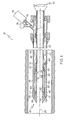
- a delivery system 10 which includes a catheter 20 which is configured to deliver a stent 30, which in at least one embodiment is a self-expanding stent.
- Catheter 20 includes a catheter shaft or inner shaft 22, a portion of which defines a stent receiving region 24.
- Catheter shaft 22 may further define a guidewire lumen 26 through which a guidewire 28 may be passed in order to advance the catheter to a predetermined position in a body lumen or vessel.
- the shaft 22 may be configured as a fixed-wire catheter.
- the catheter 20 may be any type of catheter desired and in some embodiments may include a catheter shaft 22 having a substantially hexagonal cross-sectional shape.
- a stent 30 may be a self-expanding stent which is disposed about the stent receiving region 24 of the catheter shaft 22.
- the stent may be at least partially constructed from one or more of the following shape memory materials: nitinol, shape-memory polymer(s), etc., but may include other material or materials as well.
- the stent is at least partially constructed of stainless steel, cobalt, chromium, titanium, nickel, and any combinations or alloys thereof.
- the stent includes one or more areas, bands, coatings, members etc that is (are) detectable by imaging modalities such as X-Ray, MRI or ultrasound. In some embodiments at least a portion of the stent 30 is at least partially radiopaque.
- the stent 30 may include one or more therapeutic and/or lubricious coatings 50 applied thereto.
- a therapeutic agent may be included with the stent.
- the agent is placed on the stent in the form of a coating 50.
- the coating 50 includes at least one therapeutic agent and at least one polymer agent.
- a therapeutic agent may be a drug or other pharmaceutical product such as non-genetic agents, genetic agents, cellular material, etc.
- suitable non-genetic therapeutic agents include but are not limited to: anti-thrombogenic agents such as heparin, heparin derivatives, vascular cell growth promoters, growth factor inhibitors, Paclitaxel, etc.
- an agent includes a genetic therapeutic agent, such a genetic agent may include but is not limited to: DNA, RNA and their respective derivatives and/or components; hedgehog proteins, etc.
- the cellular material may include but is not limited to: cells of human origin and/or non-human origin as well as their respective components and/or derivatives thereof.
- the agent may be a polystyrene-polyisobutylene-polystyrene triblock copolymer (SIBS), polyethylene oxide, silicone rubber and/or any other suitable substrate.
- SIBS polystyrene-polyisobutylene-polystyrene triblock copolymer
- silicone rubber any other suitable substrate.
- the at least a portion of the stent may include a stent covering.
- the covering may be constructed of a variety of materials such as Dacron, PTFE, etc.
- the covering comprises at least one therapeutic agent.
- the stent 30 is preferably configured to be at least partially self-expanding or have self-expanding characteristics.
- self-expanding refers to the tendency of the stent to return to a predetermined diameter when unrestrained from the catheter, such as in the manner depicted in FIGs. 1-3 .
- the stent is restrained in its reduced diameter or pre-delivery configuration by retractable sheath 40 which is disposed about the entire length of the stent 30 prior to delivery.
- the sheath 40 includes a stent retaining region 42, which refers to that region of the sheath 40 which is disposed about the stent 30 prior to delivery.
- a stent retaining region 42 Engaged to a portion of the stent retaining region 42 is a roll back sleeve or membrane 44.
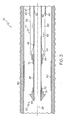
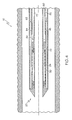
- the sheath 40 is retracted proximally, which causes the membrane 44 to roll back off of the stent in the manner illustrated in FIGs. 2-3 .
- the membrane 44 comprises a distal end region 43 and a proximal end region 45.
- the proximal end region 45 is engaged to a portion of the inner shaft 22 proximal to the stent receiving region 24.
- the distal end region 43 of the membrane is engaged to a distal end portion 47 of the sheath 40 at an engagement region 46.
- the membrane 44 and sheath 40 may be engaged together by any mechanism and/or configuration desired.
- region 43 and portion 47 may be engaged together by chemical, or adhesive welding or bonding, fusion or heat welding, ultrasonic welding, etc.; they may be mechanically engaged along complementary surfaces; an additional component such as a fastener or other device may be utilized to secure the components together, etc.
- the membrane 44 and the sheath 40 may be butt-welded or joined, or lap-welded or joined.
- the distal end region 43 of the membrane 44 can be folded back upon itself to engage the distal end region of the sheath 40. This results in effectively engaging the inside surface (i.e. that surface which at its proximal extent is in contact with the exterior of the stent) 56 of the membrane 44 to the inside surface 57 of the sheath 40.
- This folded arrangement provides the membrane 44 with a continuous bend region 59 which not only aids in providing the membrane 44 with the tendency to roll back upon itself rather than buckle or slide during retraction, but also aids in the formation of a potential gap between the membrane 44 and sheath 40 proximal to their engagement region 46.
- this "gap" functions as a fluid lumen or chamber 60 into which a fluid, represented by arrows 62, from a fluid source 76 (such as a syringe, etc) may be transported via a fluid port 73 at the proximal end region 74 of the catheter 20.
- the proximal end region 74 of the catheter may have any handle configuration desired and may have any desired mechanism for regulating the flow of fluid 62 into and/or out of the chamber 60.
- the catheter 20 may include a pressure gauge 75 or other mechanism for monitoring and regulating to volume, flow rate, and/or pressure of the fluid 62 with in the catheter.
- the fluid chamber 60 acts as a lumen to transport the fluid distally into the area of the stent retaining region of the sheath 40.
- the proximal portion of the chamber or lumen 60 is defined by the sheath 40 and the inner shaft 22.
- the distal region of the chamber 60 is defined by the sheath 40 and the membrane 44.
- fluid 62 may be in the form of a coating, such as a lubricious hydrogel, saline, etc. which aids in reducing the potential frictional interactions between the sheath 40 and membrane 44
- a volume of fluid 62 may be injected into the lumen 60 under a predetermined pressure which is maintained during the stent delivery process depicted in FIGs. 2 and 3 .
- the use of fluid 62 under pressure keeps the gap between the sheath 40 and membrane 44 open throughout the retraction process effectively minimizing any sliding friction therebetween, as well as limiting the frictional forces resulting from the stent's tendency to push outward against the sheath 40. As illustrated in FIG.
- the pressure exerted by the fluid 62 against the membrane 44 maintains the membrane 44 over the stent and provides the folded over membrane 44 with a turgid-like state sufficient to retain a portion of the stent 30 thereunder in the reduced state until the membrane 44 is retracted.
- the pressure exerted by fluid 62 on the membrane 44 may be monitored and regulated by the pressure gauge 75, such as is shown in FIG. 1 .
- a desired pressure of fluid 62 may be maintained within the chamber 60 by the use of any of a variety of devices such as stop-cocks, relief valves, etc.
- the stent When the sheath 40 and the membrane 44 are fully withdrawn from about the stent 30, the stent is delivered into a desired location within a body lumen or vessel.
- the sheath 40 and particularly the distal portion or stent retaining region 42 of the sheath, is configured to retain the stent 30 in its reduced or pre-delivery diameter
- at least the stent retaining region 42 of the sheath 40 is constructed to have sufficient hoop strength to prevent the stent from expanding off of the stent receiving region 24 until the sheath 40 is retracted.
- At least the stent retaining region 42 of the sheath 40 may be constructed from one or more of the materials including but not limited to: polymer materials such as Pebax, Hytrel, Arnitel, Nylon, etc.
- the stiffness of the sheath 40 can be varied by changing the polymer durometers from the proximal end to the distal end by any manner desired.
- the sheath 40 comprises a multi-layer construction wherein one or more materials are layered, braided or otherwise combined to form the sheath 40.
- the sheath 40 may be provided with a PTFE liner or such a liner may be absent. Where a liner is provided, an inner PTFE liner may be braided with an additional polymer as desired.
- the sheath 40 is of the same or similar construction as a guide catheter.
- the sheath 40 is at least partially constructed of a clear polymer.
- a clear polymer may be used to provide the sheath 40 with a substantially clear distal end region. The clear distal end would allow for viewing the stent or implant device in a constrained state under the sheath.
- the inside of the sheath is coated for enhanced lubricity.
- the sheath 40 While the stent retaining region 42 of the sheath 40 is typically constructed to have greater hoop strength than the membrane 44, the sheath may be less flexible than the membrane 44 as well.
- the membrane 44 may be at least partially constructed of one or more of a variety of flexible materials such as including but not limited to: Pebax, PET, Nylon, POC, Polyurethane, etc.
- the material of the membrane 44 may include those which are nanoceramic for added durability.
- the membrane 44 is at least partially made from one or more polymers with surface alterations such as plasma treatment for enhanced lubricity.
- the membrane 44 comprises one or more layers of material.
- one or both sides of the membrane 44 are coated and/or provided with surface enhancements. Coating can include silicones or other substances to enhance lubricity.
- the membrane 44 is at least partially constructed from those materials from which medical balloons are known to be manufactured from. Such membrane material may be blown or extruded to any dimensions desired.
- the wall thickness of the membrane may vary and may be about 0,00254 cm (0.001 inches) to no more than about 0,0127 cm (0.005 inches) thick. In at least one embodiment the thickness of the membrane is less than about 0,00254 cm (0.001 inches).
- the membrane 44 is a single layer membrane folded over upon itself at the distal end region 43 whereupon it is engaged to the sheath 40.
- the sheath 40 is retracted, the membrane 44 is pulled back off of the stent 30 as the outside fold 52 of the membrane rolls proximally on top of the inner fold 54 proximally until the entire membrane 44 is rolled off of the stent 30 such as is depicted in FIGs. 2-3 .
- a lubricant or other fluid 62 may be provided within the lumen 60 to encourage the rolling action of the folds 52 and 54 and/or separate the folds.
- the fluid 62 may be any type of "inflation fluid" such as may be utilized in balloon catheters which are known, and/or maybe any sort of biocompatible fluid or lubricant such as is described in U.S. 5,693,034 .
- fluid 62 is a liquid.
- a hub, flange, protrusion(s), marker or other member 70 and 72 may be positioned proximally and/or adjacent to the stent receiving region 24.
- member 72 may also be provided with a diameter sufficiently greater than the diameter of the stent in the reduced state, to thereby prevent the stent from being inadvertently displaced in the proximal direction.
- the stent 30 may be crimped onto, or disposed about, one or more of the members 70 and/or 72, and/or the catheter 20 may be provided any of the variety of stent retaining mechanisms that are known.
- Members 70 and/or 72 may also include any known or later developed type of fixation system for reducing the likelihood of stent displacement prior to and/or during deployment.
- Members 70 and/or 72 may be configured to be detectable by imaging modalities such as X-Ray, MRI or ultrasound. In some embodiments at least a portion of one or both members is at least partially radiopaque.
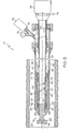
- the catheter 20 is provided with a secondary lumen 80 which is formed between an intermediate shaft or mid-shaft 82 and the inner shaft 22 proximal to the stent receiving region 24.
- the proximal end region 45 of the membrane 44 is engaged to a distal portion 84 of the mid-shaft 82.
- This modified system 10 provides a secondary lumen 80 which extends into the stent receiving region 24 of the catheter 20 which underlies the membrane 44.
- the secondary lumen 80 provides a flush path through which a fluid 64 may be transported to the stent receiving region 24 during or prior to delivery of the stent 30.
- Fluid 64 may be similar or different than fluid 62.
- Flushing the stent receiving region 24 prior to delivery of the stent 30 and/or prior to use of the device 10 will not only purge the region 24 of air but will also act to reduce frictional engagement of the stent 30 and the membrane 44 prior to and/or during retraction of the membrane 44. Flushing can also be used to hydrate the shaft walls and/or the stent.
- a system 10 of the type shown in FIGs. 1-3 may also be provided with a flush path for flushing the stent receiving region 24 of the catheter 20 prior to use.
- a flush path is defined by the guidewire lumen 26 and one or more holes or ports 86 through the stent receiving region 24 of the catheter shaft 22. Ports 86 provide fluid communication between the guidewire lumen 26 and the stent receiving region 24.
- the ports 86 may be configured as a one-way valve to allow fluid to exit the guidewire lumen 26 but not re-enter.
Landscapes
- Health & Medical Sciences (AREA)
- Engineering & Computer Science (AREA)
- Biomedical Technology (AREA)
- Cardiology (AREA)
- Oral & Maxillofacial Surgery (AREA)
- Transplantation (AREA)
- Heart & Thoracic Surgery (AREA)
- Vascular Medicine (AREA)
- Life Sciences & Earth Sciences (AREA)
- Animal Behavior & Ethology (AREA)
- General Health & Medical Sciences (AREA)
- Public Health (AREA)
- Veterinary Medicine (AREA)
- Materials For Medical Uses (AREA)
- Media Introduction/Drainage Providing Device (AREA)
- Prostheses (AREA)
Claims (25)
- Medizinische Vorrichtung, umfassend:einen Katheter (20), wobei der Katheter einen Katheterschaft (22) hat und ein Abschnitt des Katheterschaftes ein Stentaufnahmegebiet (24) definiert,eine Hülle (40), wobei die Hülle über dem Katheterschaft angeordnet ist und in Bezug auf diesen in Längsrichtung verschiebbar ist, ein distaler Abschnitt der Hülle ein Stenthaltegebiet (42) definiert, die Hülle zwischen einer ausgefahrenen Stellung und einer zurückgezogenen Stellung verschiebbar ist, das Haltegebiet in der ausgefahrenen Stellung über dem Stentaufnahmegebiet angeordnet ist und die Hülle in der zurückgezogenen Stellung von dem Stentaufnahmegebiet abgezogen ist; undeine Membran (44), wobei ein distales Gebiet (43) der Membran mit einem distalen Abschnitt der Hülle in Eingriff ist, ein proximales Gebiet (45) der Membran mit einem zu dem Stentaufnahmegebiet proximalen Abschnitt des Katheterschaftes in Eingriff ist, in der ausgefahrenen Stellung die Membran zwischen dem Katheterschaft und der Hülle positioniert ist und ein Abschnitt der Membran über mindestens einem Abschnitt des Stentaufnahmegebietes angeordnet ist und in der zurückgezogenen Stellung die Membran von über dem mindestens einem Abschnitt des Stentaufnahmegebietes abgezogen ist.
- Medizinische Vorrichtung gemäß Anspruch 1, ferner umfassend eine Fluidkammer, wobei die Fluidkammer ein proximales Gebiet und ein distales Gebiet hat und das proximale Gebiet durch den Katheterschaft und die Hülle definiert ist und der distale Abschnitt durch die Membran und die Hülle definiert ist.
- Medizinische Vorrichtung gemäß Anspruch 3, wobei die Fluidkammer in Fluid-Verbindung mit einem Fluidanschluss ist und der Fluidanschluss dazu konstruiert und angeordnet ist, ein Fluid in die Fluidkammer aufzunehmen.
- Medizinische Vorrichtung gemäß Anspruch 1, ferner umfassend einen Stent, wobei der Stent aus einem verkleinerten Zustand zu einem ausgedehnten Zustand ausdehnbar ist, der Stent in dem verkleinerten Zustand einen geringeren Durchmesser als in dem ausgedehnten Zustand hat und wenn die Hülle in der ausgefahrenen Stellung ist, der Stent in dem verkleinerten Zustand über dem Stentaufnahmegebiet angeordnet ist.
- Medizinische Vorrichtung gemäß Anspruch 4, wobei in der ausgefahrenen Stellung der Abschnitt der Membran über dem Stent angeordnet ist.
- Medizinische Vorrichtung gemäß Anspruch 5, wobei in der ausgefahrenen Stellung der distale Endabschnitt der Membran gefaltet ist, um eine innere Falte, eine äußere Falte und ein kontinuierliches Biegungsgebiet dazwischen zu definieren, wobei die äußere Falte mit dem distalen Endabschnitt der Hülle in Eingriff ist und die innere Falte zwischen der äußeren Falte und dem Stent positioniert ist.
- Medizinische Vorrichtung gemäß Anspruch 6, wobei wenn die Hülle aus dem ausgefahrenen Zustand in den zurückgezogenen Zustand zurückgezogen wird, die äußere Falte entlang dem kontinuierlichen Biegungsgebiet in einer proximalen Längsrichtung über die innere Falte gezogen wird, bis die gesamte Membran aufrollartig von über dem Stent weg zurückgezogen ist.
- Medizinische Vorrichtung gemäß Anspruch 5, ferner umfassend ein Fluid, wobei das Fluid zwischen der inneren Falte und der äußeren Falte positioniert ist.
- Medizinische Vorrichtung gemäß Anspruch 1, ferner umfassend mindestens ein Stent-Befestigungselement, wobei das mindestens eine Stent-Befestigungselement mit dem Katheterschaft in Eingriff ist und angrenzend an das Stentaufnahmegebiet positioniert ist.
- Medizinische Vorrichtung gemäß Anspruch 4, ferner umfassend mindestens ein Stent-Befestigungselement, wobei das mindestens eine Stent-Befestigungselement mit dem Katheterschaft in Eingriff ist und angrenzend an das Stentaufnahmegebiet positioniert ist und wobei der Stent in dem verkleinerten Zustand mit dem Stent-Befestigungselement in Eingriff ist.
- Medizinische Vorrichtung gemäß Anspruch 9, wobei das mindestens eine Stent-Befestigungselement ein proximales Stent-Befestigungselement und ein distales Stent-Befestigungselement umfasst, wobei das proximale Stent-Befestigungselement angrenzend an ein proximales Ende des Stentaufnahmegebietes positioniert ist und das distale Stent-Befestigungselement angrenzend an ein distales Ende des Stentaufnahmegebietes positioniert ist.
- Medizinische Vorrichtung gemäß Anspruch 9, wobei das mindestens eine Stent-Befestigungselement mindestens teilweise Röntgen-undurchlässig ist.
- Medizinische Vorrichtung gemäß Anspruch 6, wobei das mindestens eine Stent-Befestigungselement dazu konfiguriert ist, durch mindestens eine der folgenden Detektionsarten detektierbar zu sein: Röntgenstrahlen, Magnetresonanz-Bildgebung, Ultraschall und irgendwelche Kombinationen davon.
- Medizinische Vorrichtung gemäß Anspruch 1, wobei die Hülle mindestens teilweise aus mindestens einem Polymer aus der Gruppe bestehend aus: Pebax, Hytrel, Arnitel, Nylon, PTFE und irgendwelchen Kombinationen davon aufgebaut ist.
- Medizinische Vorrichtung gemäß Anspruch 1, wobei die Membran mindestens teilweise aus mindestens einem Material aus der Gruppe bestehend aus: Pebax, PET, Nylon, POC, Polyurethan und irgendwelchen Kombinationen davon aufgebaut ist.
- Medizinische Vorrichtung gemäß Anspruch 4, wobei der Stent mindestens teilweise Röntgen-undurchlässig ist.
- Medizinische Vorrichtung gemäß Anspruch 4, wobei der Stent dazu konfiguriert ist, durch mindestens eine der folgenden Detektionsarten detektierbar zu sein: Röntgenstrahlen, Magnetresonanz-Bildgebung, Ultraschall und irgendeine Kombination davon.
- Medizinische Vorrichtung gemäß Anspruch 5, wobei mindestens ein Abschnitt des Stents mindestens ein therapeutisches Mittel umfasst.
- Medizinische Vorrichtung gemäß Anspruch 18, wobei das mindestens eine therapeutische Mittel eine Beschichtung ausgewählt aus mindestens einem Mitglied der Gruppe bestehend aus: nicht-genetischen therapeutischen Mitteln, genetischen therapeutischen Mitteln, zellulärem Material und irgendeiner Kombination davon ist.
- Medizinische Vorrichtung gemäß Anspruch 19, wobei das mindestens eine therapeutische Mittel mindestens ein Polymermittel umfasst.
- Medizinische Vorrichtung gemäß Anspruch 1, wobei der Katheterschaft ferner ein Lumen und mindestens einen Anschluss in Fluid-Kommunikation zwischen dem Lumen und dem Stentaufnahmegebiet definiert.
- Medizinische Vorrichtung gemäß Anspruch 21, ferner umfassend ein Spülfluid, wobei das Spülfluid durch das Lumen und den mindestens einen Anschluss hindurch von einem proximalen Gebiet des Katheters zu dem Stentaufnahmegebiet transportiert wird.
- Medizinische Vorrichtung, umfassend:einen Katheter (20), wobei der Katheter einen inneren Schaft (22) und einen intermediären Schaft (82) aufweist, der intermediäre Schaft über einem proximalen Abschnitt des inneren Schaftes angeordnet ist und ein distaler Abschnitt des inneren Schaftes ein Stentaufnahmegebiet (24) definiert;eine Hülle (40), wobei die Hülle über dem intermediären Schaft und dem inneren Schaft angeordnet ist und in Bezug auf diese in Längsrichtung verschiebbar ist, ein distaler Abschnitt der Hülle ein Stenthaltegebiet (42) definiert, die Hülle zwischen einer ausgefahrenen Stellung und einer zurückgezogenen Stellung verschiebbar ist, das Haltegebiet in der ausgefahrenen Stellung über dem Stentaufnahmegebiet angeordnet ist und die Hülle in der zurückgezogenen Stellung von dem Stentaufnahmegebiet abgezogen ist; undeine Membran (44), wobei ein distales Gebiet (43) der Membran mit einem distalen Abschnitt der Hülle in Eingriff ist, ein proximales Gebiet (45) der Membran mit einem distalen Abschnitt des intermediären Schafts in Eingriff ist, in der ausgefahrenen Stellung die Membran zwischen dem Stentaufnahmegebiet des inneren Schaftes und dem Stenthaltegebiet der Hülle positioniert ist und in der zurückgezogenen Stellung die Membran von über dem mindestens einem Abschnitt des Stentaufnahmegebietes abgezogen ist.
- Medizinische Vorrichtung gemäß Anspruch 23, ferner umfassend eine Fluidkammer, wobei die Fluidkammer ein proximales Gebiet und ein distales Gebiet hat und das proximale Gebiet durch den intermediären Schaft und die Hülle definiert ist und der distale Abschnitt durch die Membran und die Hülle definiert ist.
- Medizinische Vorrichtung gemäß Anspruch 24, ferner umfassend ein Fluidlumen, wobei das Fluidlumen ein proximales Gebiet und ein distales Gebiet aufweist, und wobei das proximale Gebiet durch den inneren Schaft und den intermediären Schaft definiert ist und das distale Gebiet durch die Membran und das Stentaufnahmegebiet des inneren Schaftes definiert ist.
Applications Claiming Priority (2)
| Application Number | Priority Date | Filing Date | Title |
|---|---|---|---|
| US10/912,917 US7955370B2 (en) | 2004-08-06 | 2004-08-06 | Stent delivery system |
| PCT/US2005/025166 WO2006020028A1 (en) | 2004-08-06 | 2005-07-14 | Stent delivery system |
Publications (2)
| Publication Number | Publication Date |
|---|---|
| EP1788972A1 EP1788972A1 (de) | 2007-05-30 |
| EP1788972B1 true EP1788972B1 (de) | 2010-02-17 |
Family
ID=35063173
Family Applications (1)
| Application Number | Title | Priority Date | Filing Date |
|---|---|---|---|
| EP05772202A Expired - Lifetime EP1788972B1 (de) | 2004-08-06 | 2005-07-14 | System zum anbringen eines stents |
Country Status (7)
| Country | Link |
|---|---|
| US (1) | US7955370B2 (de) |
| EP (1) | EP1788972B1 (de) |
| JP (1) | JP4881302B2 (de) |
| AT (1) | ATE457704T1 (de) |
| CA (1) | CA2567362C (de) |
| DE (1) | DE602005019423D1 (de) |
| WO (1) | WO2006020028A1 (de) |
Families Citing this family (153)
| Publication number | Priority date | Publication date | Assignee | Title |
|---|---|---|---|---|
| WO2003003944A2 (en) | 2001-07-06 | 2003-01-16 | Angiomed Gmbh & Co. Medizintechnik Kg | Delivery system having a rapid pusher assembly for self-expanding stent, and stent exchange configuration |
| US6863683B2 (en) * | 2001-09-19 | 2005-03-08 | Abbott Laboratoris Vascular Entities Limited | Cold-molding process for loading a stent onto a stent delivery system |
| GB0123633D0 (en) | 2001-10-02 | 2001-11-21 | Angiomed Ag | Stent delivery system |
| US6866679B2 (en) | 2002-03-12 | 2005-03-15 | Ev3 Inc. | Everting stent and stent delivery system |
| US8568467B2 (en) | 2003-01-15 | 2013-10-29 | Angiomed Gmbh & Co. Medizintechnik Kg | Trans-luminal surgical device |
| GB0327306D0 (en) * | 2003-11-24 | 2003-12-24 | Angiomed Gmbh & Co | Catheter device |
| GB0309616D0 (en) | 2003-04-28 | 2003-06-04 | Angiomed Gmbh & Co | Loading and delivery of self-expanding stents |
| US7393358B2 (en) * | 2004-08-17 | 2008-07-01 | Boston Scientific Scimed, Inc. | Stent delivery system |
| WO2006042114A1 (en) | 2004-10-06 | 2006-04-20 | Cook, Inc. | Emboli capturing device having a coil and method for capturing emboli |
| US20060116572A1 (en) * | 2004-12-01 | 2006-06-01 | Case Brian C | Sensing delivery system for intraluminal medical devices |
| DE102006039823A1 (de) * | 2005-02-25 | 2008-03-20 | Strecker, Ernst Peter, Prof. Dr. med. | Katheter-Stent-Vorrichtung |
| US7632296B2 (en) * | 2005-03-03 | 2009-12-15 | Boston Scientific Scimed, Inc. | Rolling membrane with hydraulic recapture means for self expanding stent |
| US8221446B2 (en) | 2005-03-15 | 2012-07-17 | Cook Medical Technologies | Embolic protection device |
| US8945169B2 (en) | 2005-03-15 | 2015-02-03 | Cook Medical Technologies Llc | Embolic protection device |
| FR2885794B1 (fr) * | 2005-05-19 | 2007-08-17 | Perouse Soc Par Actions Simpli | Necessaire de largage d'un organe de traitement d'une cavite et procede de preparation d'un organe de traitement associe |
| US8435279B2 (en) * | 2005-06-14 | 2013-05-07 | Advanced Cardiovascular Systems, Inc. | Delivery system for a device such as a stent |
| US8187298B2 (en) | 2005-08-04 | 2012-05-29 | Cook Medical Technologies Llc | Embolic protection device having inflatable frame |
| US8377092B2 (en) * | 2005-09-16 | 2013-02-19 | Cook Medical Technologies Llc | Embolic protection device |
| US8632562B2 (en) | 2005-10-03 | 2014-01-21 | Cook Medical Technologies Llc | Embolic protection device |
| US8182508B2 (en) | 2005-10-04 | 2012-05-22 | Cook Medical Technologies Llc | Embolic protection device |
| US8252017B2 (en) | 2005-10-18 | 2012-08-28 | Cook Medical Technologies Llc | Invertible filter for embolic protection |
| US7637933B2 (en) * | 2005-11-01 | 2009-12-29 | Cordis Corporation | Method for preparing and employing an implant delivery apparatus |
| US8216269B2 (en) * | 2005-11-02 | 2012-07-10 | Cook Medical Technologies Llc | Embolic protection device having reduced profile |
| US8152831B2 (en) | 2005-11-17 | 2012-04-10 | Cook Medical Technologies Llc | Foam embolic protection device |
| US20070208350A1 (en) * | 2006-03-06 | 2007-09-06 | Gunderson Richard C | Implantable medical endoprosthesis delivery systems |
| US7621946B2 (en) * | 2006-03-06 | 2009-11-24 | Boston Scientific Scimed, Inc. | Implantable medical endoprosthesis delivery system with hub |
| US20070208405A1 (en) * | 2006-03-06 | 2007-09-06 | Boston Scientific Scimed, Inc. | Stent delivery catheter |
| US8333000B2 (en) | 2006-06-19 | 2012-12-18 | Advanced Cardiovascular Systems, Inc. | Methods for improving stent retention on a balloon catheter |
| US20080071307A1 (en) | 2006-09-19 | 2008-03-20 | Cook Incorporated | Apparatus and methods for in situ embolic protection |
| US8177798B2 (en) * | 2006-12-05 | 2012-05-15 | Tyco Healthcare Group Lp | Adhesive coated stent and insertion instrument |
| US9901434B2 (en) | 2007-02-27 | 2018-02-27 | Cook Medical Technologies Llc | Embolic protection device including a Z-stent waist band |
| US8764816B2 (en) * | 2007-05-07 | 2014-07-01 | W. L. Gore & Associates, Inc. | Stent delivery and deployment system |
| US7981148B2 (en) * | 2007-05-16 | 2011-07-19 | Boston Scientific Scimed, Inc. | Stent delivery catheter |
| US8419748B2 (en) | 2007-09-14 | 2013-04-16 | Cook Medical Technologies Llc | Helical thrombus removal device |
| US9138307B2 (en) * | 2007-09-14 | 2015-09-22 | Cook Medical Technologies Llc | Expandable device for treatment of a stricture in a body vessel |
| US8252018B2 (en) | 2007-09-14 | 2012-08-28 | Cook Medical Technologies Llc | Helical embolic protection device |
| CA2701576C (en) * | 2007-10-17 | 2016-06-21 | Angiomed Gmbh & Co. Medizintechnik Kg | Delivery system for a self-expanding device for placement in a bodily lumen |
| US20090187211A1 (en) * | 2007-12-21 | 2009-07-23 | Abbott Laboratories | Vena cava filter having hourglass shape |
| US8845712B2 (en) * | 2008-01-15 | 2014-09-30 | W. L. Gore & Associates, Inc. | Pleated deployment sheath |
| GB0815339D0 (en) * | 2008-08-21 | 2008-10-01 | Angiomed Ag | Method of loading a stent into a sheath |
| WO2009135934A1 (en) * | 2008-05-09 | 2009-11-12 | Angiomed Gmbh & Co. Medizintechnik Kg | Method of loading a stent into a sheath |
| US9750625B2 (en) | 2008-06-11 | 2017-09-05 | C.R. Bard, Inc. | Catheter delivery device |
| GB0810749D0 (en) | 2008-06-11 | 2008-07-16 | Angiomed Ag | Catherter delivery device |
| US20090312832A1 (en) * | 2008-06-13 | 2009-12-17 | Cook Incorporated | Slip layer delivery catheter |
| US8721714B2 (en) * | 2008-09-17 | 2014-05-13 | Medtronic Corevalve Llc | Delivery system for deployment of medical devices |
| EP2196174B1 (de) | 2008-12-12 | 2014-02-26 | Abbott Laboratories Vascular Enterprises Limited | Verfahren zum Laden eines Stents auf das Stenteinbringungssystem |
| US8388644B2 (en) | 2008-12-29 | 2013-03-05 | Cook Medical Technologies Llc | Embolic protection device and method of use |
| GB0823716D0 (en) * | 2008-12-31 | 2009-02-04 | Angiomed Ag | Stent delivery device with rolling stent retaining sheath |
| GB0901496D0 (en) | 2009-01-29 | 2009-03-11 | Angiomed Ag | Delivery device for delivering a stent device |
| US20100249815A1 (en) * | 2009-03-25 | 2010-09-30 | Cook Incorporated | Everted sheath thrombectomy device |
| JP5466882B2 (ja) * | 2009-05-21 | 2014-04-09 | 川澄化学工業株式会社 | 管状治療具留置装置 |
| GB0909319D0 (en) | 2009-05-29 | 2009-07-15 | Angiomed Ag | Transluminal delivery system |
| US20110009943A1 (en) | 2009-07-09 | 2011-01-13 | Paul Ram H | Delivery system with medical device release by evertable sleeve |
| US8435282B2 (en) | 2009-07-15 | 2013-05-07 | W. L. Gore & Associates, Inc. | Tube with reverse necking properties |
| US8936634B2 (en) | 2009-07-15 | 2015-01-20 | W. L. Gore & Associates, Inc. | Self constraining radially expandable medical devices |
| WO2011017189A1 (en) * | 2009-08-04 | 2011-02-10 | Wilson-Cook Medical Inc. | Roll sleeve mechanism for proximal release stent delivery device |
| US20110106234A1 (en) * | 2009-10-30 | 2011-05-05 | Axel Grandt | Interluminal medical treatment devices and methods |
| US20110118817A1 (en) * | 2009-11-17 | 2011-05-19 | Boston Scientific Scimed, Inc. | Stent delivery system |
| GB0921237D0 (en) | 2009-12-03 | 2010-01-20 | Angiomed Ag | Stent device delivery system and method of making such |
| GB0921236D0 (en) * | 2009-12-03 | 2010-01-20 | Angiomed Ag | Stent device delivery system and method of making such |
| GB0921240D0 (en) | 2009-12-03 | 2010-01-20 | Angiomed Ag | Stent device delivery system and method of making such |
| GB0921238D0 (en) | 2009-12-03 | 2010-01-20 | Angiomed Ag | Stent device delivery system and method of making such |
| US8016872B2 (en) * | 2009-12-22 | 2011-09-13 | Cook Medical Technologies Llc | Deployment and dilation with an expandable roll sock delivery system |
| US8740976B2 (en) | 2010-04-21 | 2014-06-03 | Medtronic, Inc. | Transcatheter prosthetic heart valve delivery system with flush report |
| GB201010766D0 (en) | 2010-06-25 | 2010-08-11 | Angiomed Ag | Delivery system for a self-expanding implant |
| US8585748B2 (en) | 2010-08-12 | 2013-11-19 | Cook Medical Technologies Llc | Vacuum assist delivery system |
| BR112013006296A2 (pt) * | 2010-09-17 | 2016-06-07 | St Jude Medical Cardiology Div | dispositivo e sistema de colocação para uma válvula cardíaca protética flexível, método para limpar um dispositivo de colocação para uma válvula cardíaca protética flexível |
| US9931232B2 (en) | 2010-10-21 | 2018-04-03 | Boston Scientific Scimed, Inc. | Stent delivery system |
| WO2012068389A1 (en) | 2010-11-17 | 2012-05-24 | Boston Scientific Scimed, Inc. | Stent delivery system |
| EP2640320B1 (de) | 2010-11-17 | 2018-04-18 | Boston Scientific Scimed, Inc. | Stentträgersystem |
| AU2011329446B2 (en) | 2010-11-17 | 2015-12-24 | Boston Scientific Scimed, Inc. | Stent delivery systems and locking members for use with stent delivery systems |
| GB201020373D0 (en) | 2010-12-01 | 2011-01-12 | Angiomed Ag | Device to release a self-expanding implant |
| EP2510972B1 (de) * | 2011-04-14 | 2014-08-06 | Biotronik AG | Kathetervorrichtung |
| US20120330342A1 (en) * | 2011-06-27 | 2012-12-27 | Jones Donald K | Systems and devices for intralumenal implantation |
| US20120330350A1 (en) * | 2011-06-27 | 2012-12-27 | Jones Donald K | Methods and systems for performing thrombectomy procedures |
| US10213329B2 (en) * | 2011-08-12 | 2019-02-26 | W. L. Gore & Associates, Inc. | Evertable sheath devices, systems, and methods |
| US8945146B2 (en) | 2011-10-24 | 2015-02-03 | Medtronic, Inc. | Delivery system assemblies and associated methods for implantable medical devices |
| US10058443B2 (en) | 2011-11-02 | 2018-08-28 | Boston Scientific Scimed, Inc. | Stent delivery systems and methods for use |
| US9216293B2 (en) * | 2011-11-17 | 2015-12-22 | Medtronic, Inc. | Delivery system assemblies for implantable medical devices |
| US8721587B2 (en) | 2011-11-17 | 2014-05-13 | Medtronic, Inc. | Delivery system assemblies and associated methods for implantable medical devices |
| US10213187B1 (en) | 2012-01-25 | 2019-02-26 | Mubin I. Syed | Method and apparatus for percutaneous superficial temporal artery access for carotid artery stenting |
| US10940167B2 (en) | 2012-02-10 | 2021-03-09 | Cvdevices, Llc | Methods and uses of biological tissues for various stent and other medical applications |
| US9072624B2 (en) | 2012-02-23 | 2015-07-07 | Covidien Lp | Luminal stenting |
| US20130226278A1 (en) | 2012-02-23 | 2013-08-29 | Tyco Healthcare Group Lp | Methods and apparatus for luminal stenting |
| US9078659B2 (en) | 2012-04-23 | 2015-07-14 | Covidien Lp | Delivery system with hooks for resheathability |
| US20130304180A1 (en) | 2012-05-09 | 2013-11-14 | Michael L. Green | Catheter having dual balloon hydraulic actuator |
| US9271855B2 (en) * | 2012-05-09 | 2016-03-01 | Abbott Cardiovascular Systems Inc. | Catheter having hydraulic actuator with tandem chambers |
| US9011513B2 (en) | 2012-05-09 | 2015-04-21 | Abbott Cardiovascular Systems Inc. | Catheter having hydraulic actuator |
| US9381326B2 (en) | 2012-06-15 | 2016-07-05 | W. L. Gore & Associates, Inc. | Vascular occlusion and drug delivery devices, systems, and methods |
| US9724222B2 (en) | 2012-07-20 | 2017-08-08 | Covidien Lp | Resheathable stent delivery system |
| US9364358B2 (en) * | 2012-07-27 | 2016-06-14 | Medinol Ltd. | Catheter with retractable cover and pressurized fluid |
| US10639179B2 (en) | 2012-11-21 | 2020-05-05 | Ram Medical Innovations, Llc | System for the intravascular placement of a medical device |
| CH707319A1 (de) | 2012-12-11 | 2014-06-13 | Carag Ag | Stentapplikator. |
| US9907641B2 (en) | 2014-01-10 | 2018-03-06 | W. L. Gore & Associates, Inc. | Implantable intraluminal device |
| US20140228937A1 (en) | 2013-02-11 | 2014-08-14 | Joshua Krieger | Expandable Support Frame and Medical Device |
| US9763819B1 (en) | 2013-03-05 | 2017-09-19 | W. L. Gore & Associates, Inc. | Tapered sleeve |
| US9192499B2 (en) | 2013-03-11 | 2015-11-24 | Cook Medical Technologies Llc | Inner catheter for a self-expanding medical device delivery system with a closed coil wire |
| US10531971B2 (en) | 2013-03-12 | 2020-01-14 | Abbott Cardiovascular System Inc. | Balloon catheter having hydraulic actuator |
| US9333077B2 (en) | 2013-03-12 | 2016-05-10 | Medtronic Vascular Galway Limited | Devices and methods for preparing a transcatheter heart valve system |
| US9283101B2 (en) | 2013-03-12 | 2016-03-15 | Abbott Cardiovascular Systems Inc. | Catheter having hydraulic actuator and locking system |
| US10420662B2 (en) | 2013-03-12 | 2019-09-24 | Abbott Cardiovascular Systems Inc. | Catheter having movable tubular structure and proximal stopper |
| US9498364B2 (en) | 2013-03-29 | 2016-11-22 | Cook Medical Technologies Llc | Medical device delivery system and method of flushing same |
| EP2813195A1 (de) | 2013-06-13 | 2014-12-17 | Cardiatis S.A. | Stenteinführungssystem |
| US10130500B2 (en) | 2013-07-25 | 2018-11-20 | Covidien Lp | Methods and apparatus for luminal stenting |
| US9782186B2 (en) | 2013-08-27 | 2017-10-10 | Covidien Lp | Vascular intervention system |
| US10045867B2 (en) | 2013-08-27 | 2018-08-14 | Covidien Lp | Delivery of medical devices |
| EP3073961B1 (de) * | 2013-11-28 | 2023-09-06 | Innoventions Ltd. | Filtrations- und einschlussvorrichtung |
| US10966850B2 (en) | 2014-03-06 | 2021-04-06 | W. L. Gore & Associates, Inc. | Implantable medical device constraint and deployment apparatus |
| EP3206634B1 (de) * | 2014-10-14 | 2019-07-03 | Colospan Ltd. | Vorrichtung zur freisetzung einer vorrichtung in einem hohlorgan |
| US10583022B2 (en) * | 2014-11-19 | 2020-03-10 | Boston Scientific Scimed, Inc. | Stent delivery systems with a reconstraining member |
| US10159587B2 (en) | 2015-01-16 | 2018-12-25 | Boston Scientific Scimed, Inc. | Medical device delivery system with force reduction member |
| US9636244B2 (en) * | 2015-04-09 | 2017-05-02 | Mubin I. Syed | Apparatus and method for proximal to distal stent deployment |
| AU2016305298B2 (en) | 2015-08-11 | 2020-11-12 | Mokita Medical Gmbh I.Gr. | Systems and methods for removing air from medical devices |
| US10610394B2 (en) | 2015-08-11 | 2020-04-07 | Mokita Medical Gmbh | Systems and methods for using perfluorocarbons to remove gases from medical devices |
| US10080675B2 (en) | 2015-08-24 | 2018-09-25 | Abbott Cardiovascular Systems Inc. | System and method for conditioning an endoprosthesis |
| US10492936B2 (en) | 2015-10-30 | 2019-12-03 | Ram Medical Innovations, Llc | Apparatus and method for improved access of procedural catheter in tortuous vessels |
| US9980838B2 (en) | 2015-10-30 | 2018-05-29 | Ram Medical Innovations Llc | Apparatus and method for a bifurcated catheter for use in hostile aortic arches |
| US11020256B2 (en) | 2015-10-30 | 2021-06-01 | Ram Medical Innovations, Inc. | Bifurcated “Y” anchor support for coronary interventions |
| US10779976B2 (en) | 2015-10-30 | 2020-09-22 | Ram Medical Innovations, Llc | Apparatus and method for stabilization of procedural catheter in tortuous vessels |
| US10327929B2 (en) | 2015-10-30 | 2019-06-25 | Ram Medical Innovations, Llc | Apparatus and method for stabilization of procedural catheter in tortuous vessels |
| US11351048B2 (en) | 2015-11-16 | 2022-06-07 | Boston Scientific Scimed, Inc. | Stent delivery systems with a reinforced deployment sheath |
| CN108601925B (zh) | 2015-12-04 | 2021-06-29 | 项目莫里股份有限公司 | 用于导管和其他用途的输入和铰接系统 |
| JP6686156B2 (ja) | 2016-02-26 | 2020-04-22 | ボストン サイエンティフィック サイムド,インコーポレイテッドBoston Scientific Scimed,Inc. | 医療用デバイス及びステント送達システムを製造する方法 |
| WO2017165810A1 (en) | 2016-03-25 | 2017-09-28 | Phillip Laby | Fluid-actuated sheath displacement and articulation behavior improving systems, devices, and methods for catheters, continuum manipulators, and other uses |
| US11420021B2 (en) | 2016-03-25 | 2022-08-23 | Project Moray, Inc. | Fluid-actuated displacement for catheters, continuum manipulators, and other uses |
| US10173031B2 (en) | 2016-06-20 | 2019-01-08 | Mubin I. Syed | Interchangeable flush/selective catheter |
| EP3493774A1 (de) * | 2016-08-02 | 2019-06-12 | Boston Scientific Scimed, Inc. | Stenteinführungssystem |
| JP6564757B2 (ja) * | 2016-11-11 | 2019-08-21 | 日本ライフライン株式会社 | 治療装置 |
| US10716666B2 (en) * | 2016-12-05 | 2020-07-21 | Medtronic Vascular, Inc. | Prosthetic heart valve delivery system with controlled expansion |
| US10376396B2 (en) | 2017-01-19 | 2019-08-13 | Covidien Lp | Coupling units for medical device delivery systems |
| CN106580531B (zh) * | 2017-01-24 | 2018-03-23 | 南华大学 | 用于可膨胀支架的递送系统 |
| ES2982356T3 (es) * | 2017-04-21 | 2024-10-15 | Merit Medical Systems Inc | Endoprótesis desplegables y dispositivos, y sistemas relacionados |
| CA3077748C (en) | 2017-10-11 | 2023-01-03 | W. L. Gore & Associates, Inc | Implantable medical device constraint and deployment apparatus |
| EP3737343B1 (de) | 2018-01-10 | 2021-12-29 | Boston Scientific Scimed Inc. | Stentfreisetzungssystem mit verschiebbarem entfaltungsmechanismus |
| US10857014B2 (en) | 2018-02-18 | 2020-12-08 | Ram Medical Innovations, Llc | Modified fixed flat wire bifurcated catheter and its application in lower extremity interventions |
| US11123209B2 (en) | 2018-04-12 | 2021-09-21 | Covidien Lp | Medical device delivery |
| US10786377B2 (en) | 2018-04-12 | 2020-09-29 | Covidien Lp | Medical device delivery |
| US11071637B2 (en) | 2018-04-12 | 2021-07-27 | Covidien Lp | Medical device delivery |
| US11413176B2 (en) | 2018-04-12 | 2022-08-16 | Covidien Lp | Medical device delivery |
| US11291570B2 (en) | 2018-04-27 | 2022-04-05 | Cook Medical Technologies Llc | Hybrid stent and delivery system |
| US11065139B2 (en) * | 2019-01-08 | 2021-07-20 | Covidien Lp | Apparatuses for stent delivery and positioning to cover an access site |
| EP4721710A2 (de) | 2019-02-13 | 2026-04-08 | Boston Scientific Scimed, Inc. | Stenteinführungssysteme |
| KR102610812B1 (ko) | 2019-02-15 | 2023-12-06 | 보스톤 싸이엔티픽 싸이메드 인코포레이티드 | 스텐트 전달 시스템 |
| US11413174B2 (en) | 2019-06-26 | 2022-08-16 | Covidien Lp | Core assembly for medical device delivery systems |
| EP4243732B1 (de) * | 2020-11-13 | 2026-04-29 | Edwards Lifesciences Corporation | Vorrichtungen zur steuerung des flüssigkeitsstroms in einer abgabevorrichtung |
| US12458518B2 (en) | 2021-02-17 | 2025-11-04 | Covidien Lp | Medical device delivery devices, systems, and methods |
| US12042413B2 (en) | 2021-04-07 | 2024-07-23 | Covidien Lp | Delivery of medical devices |
| US12109137B2 (en) | 2021-07-30 | 2024-10-08 | Covidien Lp | Medical device delivery |
| US11944558B2 (en) | 2021-08-05 | 2024-04-02 | Covidien Lp | Medical device delivery devices, systems, and methods |
| EP4539783A1 (de) * | 2022-06-16 | 2025-04-23 | Edwards Lifesciences Corporation | Flüssigkeitsabdichtungsmechanismus für einen katheter |
| GB2622233A (en) * | 2022-09-07 | 2024-03-13 | Cook Medical Technologies Llc | Medical balloon assembly, use thereof, and method of deploying a medical balloon assembly |
| US12453844B2 (en) | 2023-09-22 | 2025-10-28 | JMT Medical, Inc. | Devices and methods for bile duct surgery |
| WO2025196742A2 (en) * | 2024-03-22 | 2025-09-25 | Cook Medical Technologies Llc | Devices, methods, and systems for reducing air in a delivery |
Family Cites Families (17)
| Publication number | Priority date | Publication date | Assignee | Title |
|---|---|---|---|---|
| US5222971A (en) | 1990-10-09 | 1993-06-29 | Scimed Life Systems, Inc. | Temporary stent and methods for use and manufacture |
| DE9321003U1 (de) * | 1992-12-30 | 1995-08-10 | Schneider (Usa) Inc., Plymouth, Minn. | Vorrichtung zum Ausbringen von körperimplantierbaren Stents |
| US5681345A (en) | 1995-03-01 | 1997-10-28 | Scimed Life Systems, Inc. | Sleeve carrying stent |
| ATE232067T1 (de) * | 1995-04-14 | 2003-02-15 | Boston Scient Ltd | Stentanbringungsvorrichtung mit rollmembran |
| US5788707A (en) | 1995-06-07 | 1998-08-04 | Scimed Life Systems, Inc. | Pull back sleeve system with compression resistant inner shaft |
| EP0843990B1 (de) | 1996-11-15 | 2003-07-30 | Schneider (Europe) GmbH | Ballonkatheter und Vorrichtung zum Setzen eines Stents |
| US6090456A (en) * | 1997-05-03 | 2000-07-18 | The United States Of America As Represented By The Secretary Of The Air Force | Process for large area deposition of diamond-like carbon films |
| US6019778A (en) | 1998-03-13 | 2000-02-01 | Cordis Corporation | Delivery apparatus for a self-expanding stent |
| FI114334B (fi) | 1998-09-23 | 2004-09-30 | Metso Paper Inc | Laitteisto taipumasäädettävän telan yhteydessä ja menetelmä öljyvirtauksen ohjauksessa taipumasäädettävän telan yhteydessä |
| US6544278B1 (en) | 1998-11-06 | 2003-04-08 | Scimed Life Systems, Inc. | Rolling membrane stent delivery system |
| US6059813A (en) * | 1998-11-06 | 2000-05-09 | Scimed Life Systems, Inc. | Rolling membrane stent delivery system |
| US6350277B1 (en) | 1999-01-15 | 2002-02-26 | Scimed Life Systems, Inc. | Stents with temporary retaining bands |
| US6221097B1 (en) | 1999-03-22 | 2001-04-24 | Scimed Life System, Inc. | Lubricated sleeve material for stent delivery |
| US6331186B1 (en) | 1999-03-22 | 2001-12-18 | Scimed Life Systems, Inc. | End sleeve coating for stent delivery |
| US6478814B2 (en) | 1999-06-14 | 2002-11-12 | Scimed Life Systems, Inc. | Stent securement sleeves and optional coatings and methods of use |
| US6702843B1 (en) | 2000-04-12 | 2004-03-09 | Scimed Life Systems, Inc. | Stent delivery means with balloon retraction means |
| US7744645B2 (en) * | 2003-09-29 | 2010-06-29 | Medtronic Vascular, Inc. | Laminated drug-polymer coated stent with dipped and cured layers |
-
2004
- 2004-08-06 US US10/912,917 patent/US7955370B2/en not_active Expired - Fee Related
-
2005
- 2005-07-14 EP EP05772202A patent/EP1788972B1/de not_active Expired - Lifetime
- 2005-07-14 CA CA2567362A patent/CA2567362C/en not_active Expired - Fee Related
- 2005-07-14 DE DE602005019423T patent/DE602005019423D1/de not_active Expired - Lifetime
- 2005-07-14 AT AT05772202T patent/ATE457704T1/de not_active IP Right Cessation
- 2005-07-14 WO PCT/US2005/025166 patent/WO2006020028A1/en not_active Ceased
- 2005-07-14 JP JP2007524824A patent/JP4881302B2/ja not_active Expired - Fee Related
Also Published As
| Publication number | Publication date |
|---|---|
| US7955370B2 (en) | 2011-06-07 |
| CA2567362A1 (en) | 2006-02-23 |
| CA2567362C (en) | 2012-09-11 |
| JP2008508937A (ja) | 2008-03-27 |
| DE602005019423D1 (de) | 2010-04-01 |
| US20060030923A1 (en) | 2006-02-09 |
| ATE457704T1 (de) | 2010-03-15 |
| WO2006020028A1 (en) | 2006-02-23 |
| EP1788972A1 (de) | 2007-05-30 |
| JP4881302B2 (ja) | 2012-02-22 |
Similar Documents
| Publication | Publication Date | Title |
|---|---|---|
| US7955370B2 (en) | Stent delivery system | |
| US7393358B2 (en) | Stent delivery system | |
| US7632296B2 (en) | Rolling membrane with hydraulic recapture means for self expanding stent | |
| US20050278011A1 (en) | Stent delivery system | |
| EP1996131B1 (de) | Implantierbare medizinische systeme zur verabreichung von endoprothesen | |
| US8016872B2 (en) | Deployment and dilation with an expandable roll sock delivery system | |
| US10610390B2 (en) | Implant delivery system and method of use | |
| US8152830B2 (en) | Rotating stent delivery system for side branch access and protection and method of using same | |
| KR20110056539A (ko) | 개선된 스텐트 배치를 갖는 스텐트들 및 카테터들 | |
| US20060287712A1 (en) | Bifurcation stent assembly | |
| EP1827303B1 (de) | Stent für vulnerable plaque |
Legal Events
| Date | Code | Title | Description |
|---|---|---|---|
| PUAI | Public reference made under article 153(3) epc to a published international application that has entered the european phase |
Free format text: ORIGINAL CODE: 0009012 |
|
| 17P | Request for examination filed |
Effective date: 20070209 |
|
| AK | Designated contracting states |
Kind code of ref document: A1 Designated state(s): AT BE BG CH CY CZ DE DK EE ES FI FR GB GR HU IE IS IT LI LT LU LV MC NL PL PT RO SE SI SK TR |
|
| DAX | Request for extension of the european patent (deleted) | ||
| GRAP | Despatch of communication of intention to grant a patent |
Free format text: ORIGINAL CODE: EPIDOSNIGR1 |
|
| GRAS | Grant fee paid |
Free format text: ORIGINAL CODE: EPIDOSNIGR3 |
|
| GRAA | (expected) grant |
Free format text: ORIGINAL CODE: 0009210 |
|
| AK | Designated contracting states |
Kind code of ref document: B1 Designated state(s): AT BE BG CH CY CZ DE DK EE ES FI FR GB GR HU IE IS IT LI LT LU LV MC NL PL PT RO SE SI SK TR |
|
| REG | Reference to a national code |
Ref country code: GB Ref legal event code: FG4D |
|
| REG | Reference to a national code |
Ref country code: CH Ref legal event code: EP |
|
| REG | Reference to a national code |
Ref country code: IE Ref legal event code: FG4D |
|
| REF | Corresponds to: |
Ref document number: 602005019423 Country of ref document: DE Date of ref document: 20100401 Kind code of ref document: P |
|
| REG | Reference to a national code |
Ref country code: NL Ref legal event code: VDEP Effective date: 20100217 |
|
| LTIE | Lt: invalidation of european patent or patent extension |
Effective date: 20100217 |
|
| PG25 | Lapsed in a contracting state [announced via postgrant information from national office to epo] |
Ref country code: ES Free format text: LAPSE BECAUSE OF FAILURE TO SUBMIT A TRANSLATION OF THE DESCRIPTION OR TO PAY THE FEE WITHIN THE PRESCRIBED TIME-LIMIT Effective date: 20100528 Ref country code: IS Free format text: LAPSE BECAUSE OF FAILURE TO SUBMIT A TRANSLATION OF THE DESCRIPTION OR TO PAY THE FEE WITHIN THE PRESCRIBED TIME-LIMIT Effective date: 20100617 Ref country code: LT Free format text: LAPSE BECAUSE OF FAILURE TO SUBMIT A TRANSLATION OF THE DESCRIPTION OR TO PAY THE FEE WITHIN THE PRESCRIBED TIME-LIMIT Effective date: 20100217 Ref country code: PT Free format text: LAPSE BECAUSE OF FAILURE TO SUBMIT A TRANSLATION OF THE DESCRIPTION OR TO PAY THE FEE WITHIN THE PRESCRIBED TIME-LIMIT Effective date: 20100617 |
|
| PG25 | Lapsed in a contracting state [announced via postgrant information from national office to epo] |
Ref country code: FI Free format text: LAPSE BECAUSE OF FAILURE TO SUBMIT A TRANSLATION OF THE DESCRIPTION OR TO PAY THE FEE WITHIN THE PRESCRIBED TIME-LIMIT Effective date: 20100217 Ref country code: LV Free format text: LAPSE BECAUSE OF FAILURE TO SUBMIT A TRANSLATION OF THE DESCRIPTION OR TO PAY THE FEE WITHIN THE PRESCRIBED TIME-LIMIT Effective date: 20100217 Ref country code: AT Free format text: LAPSE BECAUSE OF FAILURE TO SUBMIT A TRANSLATION OF THE DESCRIPTION OR TO PAY THE FEE WITHIN THE PRESCRIBED TIME-LIMIT Effective date: 20100217 Ref country code: SI Free format text: LAPSE BECAUSE OF FAILURE TO SUBMIT A TRANSLATION OF THE DESCRIPTION OR TO PAY THE FEE WITHIN THE PRESCRIBED TIME-LIMIT Effective date: 20100217 Ref country code: PL Free format text: LAPSE BECAUSE OF FAILURE TO SUBMIT A TRANSLATION OF THE DESCRIPTION OR TO PAY THE FEE WITHIN THE PRESCRIBED TIME-LIMIT Effective date: 20100217 |
|
| PG25 | Lapsed in a contracting state [announced via postgrant information from national office to epo] |
Ref country code: SE Free format text: LAPSE BECAUSE OF FAILURE TO SUBMIT A TRANSLATION OF THE DESCRIPTION OR TO PAY THE FEE WITHIN THE PRESCRIBED TIME-LIMIT Effective date: 20100217 Ref country code: BE Free format text: LAPSE BECAUSE OF FAILURE TO SUBMIT A TRANSLATION OF THE DESCRIPTION OR TO PAY THE FEE WITHIN THE PRESCRIBED TIME-LIMIT Effective date: 20100217 Ref country code: CY Free format text: LAPSE BECAUSE OF FAILURE TO SUBMIT A TRANSLATION OF THE DESCRIPTION OR TO PAY THE FEE WITHIN THE PRESCRIBED TIME-LIMIT Effective date: 20100217 Ref country code: EE Free format text: LAPSE BECAUSE OF FAILURE TO SUBMIT A TRANSLATION OF THE DESCRIPTION OR TO PAY THE FEE WITHIN THE PRESCRIBED TIME-LIMIT Effective date: 20100217 Ref country code: GR Free format text: LAPSE BECAUSE OF FAILURE TO SUBMIT A TRANSLATION OF THE DESCRIPTION OR TO PAY THE FEE WITHIN THE PRESCRIBED TIME-LIMIT Effective date: 20100518 Ref country code: NL Free format text: LAPSE BECAUSE OF FAILURE TO SUBMIT A TRANSLATION OF THE DESCRIPTION OR TO PAY THE FEE WITHIN THE PRESCRIBED TIME-LIMIT Effective date: 20100217 Ref country code: RO Free format text: LAPSE BECAUSE OF FAILURE TO SUBMIT A TRANSLATION OF THE DESCRIPTION OR TO PAY THE FEE WITHIN THE PRESCRIBED TIME-LIMIT Effective date: 20100217 |
|
| PG25 | Lapsed in a contracting state [announced via postgrant information from national office to epo] |
Ref country code: SK Free format text: LAPSE BECAUSE OF FAILURE TO SUBMIT A TRANSLATION OF THE DESCRIPTION OR TO PAY THE FEE WITHIN THE PRESCRIBED TIME-LIMIT Effective date: 20100217 Ref country code: CZ Free format text: LAPSE BECAUSE OF FAILURE TO SUBMIT A TRANSLATION OF THE DESCRIPTION OR TO PAY THE FEE WITHIN THE PRESCRIBED TIME-LIMIT Effective date: 20100217 Ref country code: BG Free format text: LAPSE BECAUSE OF FAILURE TO SUBMIT A TRANSLATION OF THE DESCRIPTION OR TO PAY THE FEE WITHIN THE PRESCRIBED TIME-LIMIT Effective date: 20100517 |
|
| PLBE | No opposition filed within time limit |
Free format text: ORIGINAL CODE: 0009261 |
|
| STAA | Information on the status of an ep patent application or granted ep patent |
Free format text: STATUS: NO OPPOSITION FILED WITHIN TIME LIMIT |
|
| 26N | No opposition filed |
Effective date: 20101118 |
|
| PG25 | Lapsed in a contracting state [announced via postgrant information from national office to epo] |
Ref country code: DK Free format text: LAPSE BECAUSE OF FAILURE TO SUBMIT A TRANSLATION OF THE DESCRIPTION OR TO PAY THE FEE WITHIN THE PRESCRIBED TIME-LIMIT Effective date: 20100217 |
|
| PG25 | Lapsed in a contracting state [announced via postgrant information from national office to epo] |
Ref country code: MC Free format text: LAPSE BECAUSE OF NON-PAYMENT OF DUE FEES Effective date: 20100731 |
|
| REG | Reference to a national code |
Ref country code: CH Ref legal event code: PL |
|
| PG25 | Lapsed in a contracting state [announced via postgrant information from national office to epo] |
Ref country code: LI Free format text: LAPSE BECAUSE OF NON-PAYMENT OF DUE FEES Effective date: 20100731 Ref country code: CH Free format text: LAPSE BECAUSE OF NON-PAYMENT OF DUE FEES Effective date: 20100731 |
|
| PG25 | Lapsed in a contracting state [announced via postgrant information from national office to epo] |
Ref country code: HU Free format text: LAPSE BECAUSE OF FAILURE TO SUBMIT A TRANSLATION OF THE DESCRIPTION OR TO PAY THE FEE WITHIN THE PRESCRIBED TIME-LIMIT Effective date: 20100818 Ref country code: LU Free format text: LAPSE BECAUSE OF NON-PAYMENT OF DUE FEES Effective date: 20100714 |
|
| PG25 | Lapsed in a contracting state [announced via postgrant information from national office to epo] |
Ref country code: TR Free format text: LAPSE BECAUSE OF FAILURE TO SUBMIT A TRANSLATION OF THE DESCRIPTION OR TO PAY THE FEE WITHIN THE PRESCRIBED TIME-LIMIT Effective date: 20100217 |
|
| REG | Reference to a national code |
Ref country code: FR Ref legal event code: CA Effective date: 20140513 |
|
| REG | Reference to a national code |
Ref country code: DE Ref legal event code: R082 Ref document number: 602005019423 Country of ref document: DE Representative=s name: VOSSIUS & PARTNER PATENTANWAELTE RECHTSANWAELT, DE |
|
| PGFP | Annual fee paid to national office [announced via postgrant information from national office to epo] |
Ref country code: IT Payment date: 20140717 Year of fee payment: 10 |
|
| REG | Reference to a national code |
Ref country code: DE Ref legal event code: R082 Ref document number: 602005019423 Country of ref document: DE Representative=s name: VOSSIUS & PARTNER PATENTANWAELTE RECHTSANWAELT, DE |
|
| REG | Reference to a national code |
Ref country code: DE Ref legal event code: R082 Ref document number: 602005019423 Country of ref document: DE Representative=s name: VOSSIUS & PARTNER PATENTANWAELTE RECHTSANWAELT, DE Effective date: 20141026 Ref country code: DE Ref legal event code: R081 Ref document number: 602005019423 Country of ref document: DE Owner name: BOSTON SCIENTIFIC LIMITED, BM Free format text: FORMER OWNER: BOSTON SCIENTIFIC LTD., HASTINGS, CHRIST CHURCH, BB Effective date: 20150202 Ref country code: DE Ref legal event code: R082 Ref document number: 602005019423 Country of ref document: DE Representative=s name: VOSSIUS & PARTNER PATENTANWAELTE RECHTSANWAELT, DE Effective date: 20150202 |
|
| PG25 | Lapsed in a contracting state [announced via postgrant information from national office to epo] |
Ref country code: IT Free format text: LAPSE BECAUSE OF NON-PAYMENT OF DUE FEES Effective date: 20150714 |
|
| REG | Reference to a national code |
Ref country code: FR Ref legal event code: PLFP Year of fee payment: 12 |
|
| REG | Reference to a national code |
Ref country code: FR Ref legal event code: PLFP Year of fee payment: 13 |
|
| REG | Reference to a national code |
Ref country code: FR Ref legal event code: PLFP Year of fee payment: 14 |
|
| PGFP | Annual fee paid to national office [announced via postgrant information from national office to epo] |
Ref country code: FR Payment date: 20190619 Year of fee payment: 15 |
|
| PGFP | Annual fee paid to national office [announced via postgrant information from national office to epo] |
Ref country code: IE Payment date: 20190710 Year of fee payment: 15 Ref country code: DE Payment date: 20190702 Year of fee payment: 15 |
|
| PGFP | Annual fee paid to national office [announced via postgrant information from national office to epo] |
Ref country code: GB Payment date: 20190710 Year of fee payment: 15 |
|
| REG | Reference to a national code |
Ref country code: DE Ref legal event code: R119 Ref document number: 602005019423 Country of ref document: DE |
|
| GBPC | Gb: european patent ceased through non-payment of renewal fee |
Effective date: 20200714 |
|
| PG25 | Lapsed in a contracting state [announced via postgrant information from national office to epo] |
Ref country code: FR Free format text: LAPSE BECAUSE OF NON-PAYMENT OF DUE FEES Effective date: 20200731 Ref country code: GB Free format text: LAPSE BECAUSE OF NON-PAYMENT OF DUE FEES Effective date: 20200714 |
|
| PG25 | Lapsed in a contracting state [announced via postgrant information from national office to epo] |
Ref country code: DE Free format text: LAPSE BECAUSE OF NON-PAYMENT OF DUE FEES Effective date: 20210202 |
|
| PG25 | Lapsed in a contracting state [announced via postgrant information from national office to epo] |
Ref country code: IE Free format text: LAPSE BECAUSE OF NON-PAYMENT OF DUE FEES Effective date: 20200714 |