EP1790459A2 - Fehlererkennungseinrichtung für eine Formwerkzeugverriegelungsvorrichtung - Google Patents
Fehlererkennungseinrichtung für eine Formwerkzeugverriegelungsvorrichtung Download PDFInfo
- Publication number
- EP1790459A2 EP1790459A2 EP06255989A EP06255989A EP1790459A2 EP 1790459 A2 EP1790459 A2 EP 1790459A2 EP 06255989 A EP06255989 A EP 06255989A EP 06255989 A EP06255989 A EP 06255989A EP 1790459 A2 EP1790459 A2 EP 1790459A2
- Authority
- EP
- European Patent Office
- Prior art keywords
- mold
- crosshead
- clamping device
- sensing
- proximity switch
- Prior art date
- Legal status (The legal status is an assumption and is not a legal conclusion. Google has not performed a legal analysis and makes no representation as to the accuracy of the status listed.)
- Withdrawn
Links
- 230000005856 abnormality Effects 0.000 title claims abstract description 60
- 238000001514 detection method Methods 0.000 claims abstract description 40
- 238000000034 method Methods 0.000 claims abstract description 32
- 238000001746 injection moulding Methods 0.000 claims description 22
- 230000001133 acceleration Effects 0.000 claims description 3
- 241000282472 Canis lupus familiaris Species 0.000 description 28
- 230000005540 biological transmission Effects 0.000 description 13
- 238000010586 diagram Methods 0.000 description 8
- 238000002347 injection Methods 0.000 description 2
- 239000007924 injection Substances 0.000 description 2
- 238000013459 approach Methods 0.000 description 1
- 238000006243 chemical reaction Methods 0.000 description 1
- 238000005516 engineering process Methods 0.000 description 1
- 230000007257 malfunction Effects 0.000 description 1
- 239000011347 resin Substances 0.000 description 1
- 229920005989 resin Polymers 0.000 description 1
Images
Classifications
-
- B—PERFORMING OPERATIONS; TRANSPORTING
- B29—WORKING OF PLASTICS; WORKING OF SUBSTANCES IN A PLASTIC STATE IN GENERAL
- B29C—SHAPING OR JOINING OF PLASTICS; SHAPING OF MATERIAL IN A PLASTIC STATE, NOT OTHERWISE PROVIDED FOR; AFTER-TREATMENT OF THE SHAPED PRODUCTS, e.g. REPAIRING
- B29C45/00—Injection moulding, i.e. forcing the required volume of moulding material through a nozzle into a closed mould; Apparatus therefor
- B29C45/17—Component parts, details or accessories; Auxiliary operations
- B29C45/76—Measuring, controlling or regulating
- B29C45/768—Detecting defective moulding conditions
-
- B—PERFORMING OPERATIONS; TRANSPORTING
- B29—WORKING OF PLASTICS; WORKING OF SUBSTANCES IN A PLASTIC STATE IN GENERAL
- B29C—SHAPING OR JOINING OF PLASTICS; SHAPING OF MATERIAL IN A PLASTIC STATE, NOT OTHERWISE PROVIDED FOR; AFTER-TREATMENT OF THE SHAPED PRODUCTS, e.g. REPAIRING
- B29C45/00—Injection moulding, i.e. forcing the required volume of moulding material through a nozzle into a closed mould; Apparatus therefor
- B29C45/17—Component parts, details or accessories; Auxiliary operations
- B29C45/84—Safety devices
-
- B—PERFORMING OPERATIONS; TRANSPORTING
- B29—WORKING OF PLASTICS; WORKING OF SUBSTANCES IN A PLASTIC STATE IN GENERAL
- B29C—SHAPING OR JOINING OF PLASTICS; SHAPING OF MATERIAL IN A PLASTIC STATE, NOT OTHERWISE PROVIDED FOR; AFTER-TREATMENT OF THE SHAPED PRODUCTS, e.g. REPAIRING
- B29C45/00—Injection moulding, i.e. forcing the required volume of moulding material through a nozzle into a closed mould; Apparatus therefor
- B29C45/17—Component parts, details or accessories; Auxiliary operations
- B29C2045/1784—Component parts, details or accessories not otherwise provided for; Auxiliary operations not otherwise provided for
- B29C2045/1792—Machine parts driven by an electric motor, e.g. electric servomotor
-
- B—PERFORMING OPERATIONS; TRANSPORTING
- B29—WORKING OF PLASTICS; WORKING OF SUBSTANCES IN A PLASTIC STATE IN GENERAL
- B29C—SHAPING OR JOINING OF PLASTICS; SHAPING OF MATERIAL IN A PLASTIC STATE, NOT OTHERWISE PROVIDED FOR; AFTER-TREATMENT OF THE SHAPED PRODUCTS, e.g. REPAIRING
- B29C2945/00—Indexing scheme relating to injection moulding, i.e. forcing the required volume of moulding material through a nozzle into a closed mould
- B29C2945/76—Measuring, controlling or regulating
- B29C2945/76003—Measured parameter
- B29C2945/76066—Time
- B29C2945/76076—Time duration
-
- B—PERFORMING OPERATIONS; TRANSPORTING
- B29—WORKING OF PLASTICS; WORKING OF SUBSTANCES IN A PLASTIC STATE IN GENERAL
- B29C—SHAPING OR JOINING OF PLASTICS; SHAPING OF MATERIAL IN A PLASTIC STATE, NOT OTHERWISE PROVIDED FOR; AFTER-TREATMENT OF THE SHAPED PRODUCTS, e.g. REPAIRING
- B29C2945/00—Indexing scheme relating to injection moulding, i.e. forcing the required volume of moulding material through a nozzle into a closed mould
- B29C2945/76—Measuring, controlling or regulating
- B29C2945/76003—Measured parameter
- B29C2945/76083—Position
- B29C2945/76086—Start position
-
- B—PERFORMING OPERATIONS; TRANSPORTING
- B29—WORKING OF PLASTICS; WORKING OF SUBSTANCES IN A PLASTIC STATE IN GENERAL
- B29C—SHAPING OR JOINING OF PLASTICS; SHAPING OF MATERIAL IN A PLASTIC STATE, NOT OTHERWISE PROVIDED FOR; AFTER-TREATMENT OF THE SHAPED PRODUCTS, e.g. REPAIRING
- B29C2945/00—Indexing scheme relating to injection moulding, i.e. forcing the required volume of moulding material through a nozzle into a closed mould
- B29C2945/76—Measuring, controlling or regulating
- B29C2945/76003—Measured parameter
- B29C2945/76083—Position
- B29C2945/7609—End position
-
- B—PERFORMING OPERATIONS; TRANSPORTING
- B29—WORKING OF PLASTICS; WORKING OF SUBSTANCES IN A PLASTIC STATE IN GENERAL
- B29C—SHAPING OR JOINING OF PLASTICS; SHAPING OF MATERIAL IN A PLASTIC STATE, NOT OTHERWISE PROVIDED FOR; AFTER-TREATMENT OF THE SHAPED PRODUCTS, e.g. REPAIRING
- B29C2945/00—Indexing scheme relating to injection moulding, i.e. forcing the required volume of moulding material through a nozzle into a closed mould
- B29C2945/76—Measuring, controlling or regulating
- B29C2945/76177—Location of measurement
- B29C2945/76224—Closure or clamping unit
- B29C2945/7623—Closure or clamping unit clamping or closing drive means
-
- B—PERFORMING OPERATIONS; TRANSPORTING
- B29—WORKING OF PLASTICS; WORKING OF SUBSTANCES IN A PLASTIC STATE IN GENERAL
- B29C—SHAPING OR JOINING OF PLASTICS; SHAPING OF MATERIAL IN A PLASTIC STATE, NOT OTHERWISE PROVIDED FOR; AFTER-TREATMENT OF THE SHAPED PRODUCTS, e.g. REPAIRING
- B29C2945/00—Indexing scheme relating to injection moulding, i.e. forcing the required volume of moulding material through a nozzle into a closed mould
- B29C2945/76—Measuring, controlling or regulating
- B29C2945/76344—Phase or stage of measurement
- B29C2945/76391—Mould clamping, compression of the cavity
-
- B—PERFORMING OPERATIONS; TRANSPORTING
- B29—WORKING OF PLASTICS; WORKING OF SUBSTANCES IN A PLASTIC STATE IN GENERAL
- B29C—SHAPING OR JOINING OF PLASTICS; SHAPING OF MATERIAL IN A PLASTIC STATE, NOT OTHERWISE PROVIDED FOR; AFTER-TREATMENT OF THE SHAPED PRODUCTS, e.g. REPAIRING
- B29C2945/00—Indexing scheme relating to injection moulding, i.e. forcing the required volume of moulding material through a nozzle into a closed mould
- B29C2945/76—Measuring, controlling or regulating
- B29C2945/76344—Phase or stage of measurement
- B29C2945/76394—Mould opening
-
- B—PERFORMING OPERATIONS; TRANSPORTING
- B29—WORKING OF PLASTICS; WORKING OF SUBSTANCES IN A PLASTIC STATE IN GENERAL
- B29C—SHAPING OR JOINING OF PLASTICS; SHAPING OF MATERIAL IN A PLASTIC STATE, NOT OTHERWISE PROVIDED FOR; AFTER-TREATMENT OF THE SHAPED PRODUCTS, e.g. REPAIRING
- B29C2945/00—Indexing scheme relating to injection moulding, i.e. forcing the required volume of moulding material through a nozzle into a closed mould
- B29C2945/76—Measuring, controlling or regulating
- B29C2945/76822—Phase or stage of control
- B29C2945/76869—Mould clamping, compression of the cavity
-
- B—PERFORMING OPERATIONS; TRANSPORTING
- B29—WORKING OF PLASTICS; WORKING OF SUBSTANCES IN A PLASTIC STATE IN GENERAL
- B29C—SHAPING OR JOINING OF PLASTICS; SHAPING OF MATERIAL IN A PLASTIC STATE, NOT OTHERWISE PROVIDED FOR; AFTER-TREATMENT OF THE SHAPED PRODUCTS, e.g. REPAIRING
- B29C2945/00—Indexing scheme relating to injection moulding, i.e. forcing the required volume of moulding material through a nozzle into a closed mould
- B29C2945/76—Measuring, controlling or regulating
- B29C2945/76822—Phase or stage of control
- B29C2945/76872—Mould opening
-
- B—PERFORMING OPERATIONS; TRANSPORTING
- B29—WORKING OF PLASTICS; WORKING OF SUBSTANCES IN A PLASTIC STATE IN GENERAL
- B29C—SHAPING OR JOINING OF PLASTICS; SHAPING OF MATERIAL IN A PLASTIC STATE, NOT OTHERWISE PROVIDED FOR; AFTER-TREATMENT OF THE SHAPED PRODUCTS, e.g. REPAIRING
- B29C2945/00—Indexing scheme relating to injection moulding, i.e. forcing the required volume of moulding material through a nozzle into a closed mould
- B29C2945/76—Measuring, controlling or regulating
- B29C2945/76929—Controlling method
- B29C2945/76939—Using stored or historical data sets
- B29C2945/76943—Using stored or historical data sets compare with thresholds
-
- B—PERFORMING OPERATIONS; TRANSPORTING
- B29—WORKING OF PLASTICS; WORKING OF SUBSTANCES IN A PLASTIC STATE IN GENERAL
- B29C—SHAPING OR JOINING OF PLASTICS; SHAPING OF MATERIAL IN A PLASTIC STATE, NOT OTHERWISE PROVIDED FOR; AFTER-TREATMENT OF THE SHAPED PRODUCTS, e.g. REPAIRING
- B29C45/00—Injection moulding, i.e. forcing the required volume of moulding material through a nozzle into a closed mould; Apparatus therefor
- B29C45/17—Component parts, details or accessories; Auxiliary operations
- B29C45/64—Mould opening, closing or clamping devices
- B29C45/66—Mould opening, closing or clamping devices mechanical
- B29C45/661—Mould opening, closing or clamping devices mechanical using a toggle mechanism for mould clamping
Definitions
- the present invention relates to an abnormality detecting apparatus for a mold clamping device in an electric injection molding machine.
- the movable part of the injection molding machine is driven by a motor.
- the torque of the motor is transmitted to the movable part of the injection molding machine through a belt transmission mechanism.
- the motor torque is converted by a conversion mechanism from the rotary movement of a ball screw/nut mechanism or the like to straight-line movement, moving a crosshead of the toggle mechanism so as to move a movable one of mold halves to perform closing, clamping and opening of the mold halves.
- a technology has been developed that has as its object to detect an abnormality such as a broken belt or the like and to prevent the malfunctioning of the injection molding machine.
- a method mounts a pulse generator on the crosshead of a toggle-type clamping mechanism, counts a number of pulses generated in proportion to the amount of movement of the crosshead, compares this detected pulse number with a second pulse number that is proportional to a detected number of revolutions of a motor generated by a pulse generator provided on the driving side motor, and detects an abnormality when the ratio exceeds a predetermined range ( JP 7-16901A ), as is a method that provides a first pulse generating means that detects the rotation of a driving shaft (on the motor side), a second pulse generating means that detects the rotation of a driven shaft that is driven via a power transmission belt, counts the number of clock pulses in the interval between pulses generated from the first and second pulse generating means respectively, obtains and compares the rotation speeds of the driving shaft and the driven shaft, and detects an abnormality when the difference between the two exceeds a threshold value ( JP 2003-174786A ).
- a method that links a driven pulley and a driving pulley mounted on the motor by a belt and provides one or more projections on that driven pulley, and also provides a proximity switch that detects these one or more projections and detects a breakage of the belt by the presence of ON-OFF signals from that proximity switch ( JP 2003-74649A ), as are such methods as detecting tooth-skipping of a timing belt by the passage of projections detected by a proximity switch ( JP 2003-184967A ), detecting an abnormality in the belt by detecting the tension on the belt ( JP 11-262932A ), and using the fact that the torque of the motor that drives the belt transmission mechanism declines when the belt breaks to detect belt breakage by the torque of the motor ( JP 6-182845A ).
- JP 7-16901 A and JP 2003-17478A which provide measuring means such as pulse generators on each of the motor side and the driven side and detect abnormalities in the belt transmission mechanism
- the cost of the injection molding machine increases by the extent to which measuring means such as pulse generators must be provided.
- JP 2003-74649A which detects abnormalities of the belt by whether or not the driven-side pulley is rotating, even if the driven-side pulley is rotating there is no guarantee that the crosshead and the movable mold are moving properly, and consequently, there are times when this method cannot detect abnormality in the movement of the crosshead or the movable mold due to some abnormality with the transmission mechanism.
- JP 2003-184967A and JP 11-262932A require tension detection means or measuring means that detect the amount of rotation, which increases the cost of the injection molding machine.
- the toggle mechanism in a state in which the toggle mechanism extends and generates a predetermined clamping force, the toggle mechanism itself generates a clamping force that sharply reduces the output torque of the motor that drives the crosshead of that toggle mechanism, making it difficult to detect any abnormality in the belt transmission mechanism (such as breakage of the belt) from the motor output torque.
- the present invention provides an abnormality detection apparatus for a mold clamping device, capable of reliably detecting abnormalities in a driving force transmission mechanism such as a belt transmission mechanism at low cost.
- an abnormality detecting apparatus of the present invention is applied to a mold clamping device for clamping mold halves using a toggle mechanism having a crosshead in an electric injection molding machine.
- the abnormality detecting apparatus comprises: first sensing means for sensing arrival of the crosshead at a first position; second sensing means for sensing arrival of the crosshead at a second position; measuring means for measuring time lapsing from the sensing of the arrival of the crosshead at the first position by the first sensing means in a mold clamping process; and means for outputting an abnormality detection signal when the lapsing time measured by the measuring means exceeds a reference time before the arrival of the crosshead at the second position is sensed by the second sensing means.
- the abnormality detecting apparatus comprises: first sensing means for sensing arrival of the crosshead at a first position; second sensing means for sensing arrival of the crosshead at a second position; measuring means for measuring time lapsing from the sensing of the arrival of the crosshead at the second position by the second sensing means in a mold opening process; and means for outputting an abnormality detection signal when the lapsing time measured by the measuring means exceeds reference time before the arrival of the crosshead at the first position is detected by the first sensing means.
- the first and second sensing means may comprise a dog and a proximity switch for sensing proximity of the dog.
- a proximity switch for sensing proximity of the dog.
- one proximity switch or two proximity switches may be provided.
- the first position may be set to correspond to a mold touch position where the mold halves touch each other or a position where the mold halves are separated by a predetermined distance from the mold touch position.
- the second position may be set to correspond to a lock-up position where the clamping of the mold halves is completed.
- the abnormality detecting apparatus comprises: first sensing means for sensing arrival of the crosshead at a first position; second sensing means for sensing arrival of the crosshead at a second position; measuring means for measuring time lapsing from the sensing of the arrival of the crosshead at the second position by the second sensing means in a mold opening process; and means for outputting an abnormality detection signal when the lapsing time measured by the measuring means exceeds reference time before the arrival of the crosshead at the first position is detected by the first sensing means.
- the reference time may be predetermined based on the mold touch position, the lock-up position and a speed or acceleration/deceleration of the clamping or the opening of the mold halves.
- an abnormality in the mold clamping device such as breakage of a belt of the belt transmission mechanism can be reliably detected at low cost by providing simple sensing means for sensing the position of the crosshead.
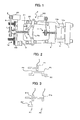
- FIG. 1 is a diagram showing an embodiment of a mold clamping device of an injection molding machine adapting a mold clamping device abnormality detection apparatus of the present invention.
- the mold clamping device abnormality detection apparatus of the present invention differs from the conventional art in that a dog 20 and a proximity switch 21 that comprise an abnormality detection apparatus are added to the conventional toggle-type mold clamping device.
- a rear platen 2 is linked to a stationary platen 1 fixedly mounted on a base of the injection molding machine by a plurality of tie bars 4.
- a movable platen 3 is guided by the tie bars 4 and disposed so as to move freely.
- a toggle mechanism 5 is placed between the rear platen 2 and the movable platen 3, with a crosshead 5a of the toggle mechanism 5 mounted on a ball nut that engages a ball crew 6, such that rotation of the ball screw 6 moves the ball nut and the crosshead 5a in the axial direction.
- the ball screw 6 is mounted on the rear platen 2 so as to rotate freely while remaining immobile in the axial direction, with a toothed pulley 7 mounted on one end of the ball screw 6.
- a servo motor M1 for a mold clamping device that drives the toggle mechanism 5 is mounted on the rear platen 2.
- a timing belt 9 is wound between a toothed pulley 8 mounted on an output shaft of the servo motor M1 and the toothed pulley 7 mounted on the ball screw 6.
- a stationary mold half 10a is mounted on the stationary platen 1 and a movable mold half 10b is mounted on the movable platen 3.
- An ejector mechanism 11 that ejects a molded article from inside the mold is provided on the movable platen 3.
- Reference symbol M2 designates a servo motor that drives the ejector mechanism 11, with an ejector pin driven by the servo motor M2 via a belt transmission mechanism and a ball screw/nut mechanism.
- a mold thickness adjustment mechanism 12 that advances and retracts the rear platen 2 along the tie bars 4 is provided on the distal end of the tie bars 4.
- Reference symbol M3 designates a motor that drives the mold thickness adjustment mechanism 12.
- the mold thickness adjustment mechanism 12 motor M3 is activated, and the thickness of the mold to be used as well as the position of the rear platen 2 are determined by moving the rear platen 2 so as to generate a set mold clamping force at a lock-up position to which the toggle mechanism 5 link is extended and adjusting for the thickness of the mold, the mold clamping device servo motor M1 is driven, the toggle mechanism 5 crosshead 5a is advanced (that is, moved to the right in FIG. 1), the movable platen 3 as well as the movable mold half 10b are advanced, the mold is closed and the mold is clamped. This is the mold clamping process.
- resin is injected into the interior of the mold by an injection mechanism, not shown, pressurized, and cooled, after which the servo motor M1 is activated and the mold is opened in the execution of a mold opening process.
- the ejector mechanism 11 servo motor M2 is activated and the molded article is removed from the interior of the mold.
- the present invention adds to the mold clamping device an abnormality detection apparatus that detects abnormalities in the mold clamping device.
- an abnormality detection apparatus that detects abnormalities in the mold clamping device.
- a dog 20 is mounted on the crosshead 5a and a proximity switch 21 that detects the dog 20 is provided on the rear platen 2 opposite the dog 20.
- the dog 20 and the proximity switch 21 detect the interval of movement of the crosshead 5a in the interval from the mold touch position to the lock-up f the toggle mechanism 5 and detect any abnormality in the belt transmission mechanism from the movement time of the crosshead 5a in this interval.
- FIG. 2 is a diagram illustrating a first embodiment of the dog 20 and the proximity switch 21 (this first embodiment is that shown in FIG. 1).
- the proximity switch 21 outputs an ON signal when a projecting surface (detection surface) of the dog 21 approaches the proximity switch 21.
- the crosshead 5a moves to the right, closing and clamping the mold in the mold clamping process, and the proximity switch 21 is disposed so as to detect the right edge of the projecting surface (the detection surface) of the dog 20 that moves together with the crosshead 5a at a mold touch position or when the mold is open at a predetermined distance from the mold touch position.
- the proximity switch 21 detects the right edge of the projecting surface (the detection surface) of the dog 20 and switches ON. Then, at a position at which the toggle mechanism 5 extends and locks up and generates a pre-set clamping force (hereinafter this position is called a second position P2), the left edge of the projecting surface (the detection surface) of the dog 20 is positioned opposite the proximity switch 21 and the proximity switch 21 switches OFF.
- the dog 20 and a single proximity switch 21 constitute first and second means for detecting the first position P1 and the second position P2.
- the amount of movement of the crosshead 5a changes depending on the size of the pre-set clamping force.
- the length of the projecting surface (the detection surface) of the dog 20 is given a certain amount of leeway, that is, a length extending from a position prior to mold touch to the lock-up position.
- differences in the pre-set clamping force produce slight variations in the distance between the mold touch position and the first position P1.
- the length of the projecting surface (the detection surface) of the dog 20 may be made adjustable, and further, multiple dogs 20 having different projecting surface (detection surface) lengths may be easily provided, with the optimum dog 20 mounted on the crosshead 5a.
- FIG. 3 is a diagram showing a second embodiment of the dog and the proximity switch in the first embodiment of the present invention.
- two proximity switches 21 a, 21 b detect a dog 20', with the first proximity switch 21 a disposed at a position at which it detects the first position P1 described above and switches ON and the second proximity switch 21 b positioned at a position at which it detects the second position P2 and switches ON.
- the second proximity switch 21b maintains an ON state in a state in which the movement of the crosshead 5a has stopped in a lock-up state.
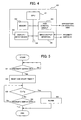
- FIG. 4 is a block diagram of essential parts of a controller for controlling the injection molding machine.
- the structure of a controller 30 is the same as that of the conventional controller, an outline of which is shown schematically in FIG. 4.
- the controller 30 comprises a processor (CPU) 31, a ROM, RAM or other such memory 32, a display/input device 33 composed of a display device consisting of a CRT or LCD and input means consisting of a keyboard and the like, an axial control circuit 34 that controls the driving of the servo motors that move the movable parts of the injection molding machine such as the mold clamping device and the injection mechanism, and an input/output interface, all connected by a bus 36.
- a processor CPU
- ROM read only memory
- RAM random access memory
- a display/input device 33 composed of a display device consisting of a CRT or LCD and input means consisting of a keyboard and the like
- an axial control circuit 34 that controls the driving of the servo motors that move the movable parts of the injection molding machine such as the mold clamping device and the injection mechanism
- an input/output interface
- controller 30 differs not at all from the conventional injection molding machine controller 30, it does differ from the conventional art insofar as software for detecting abnormalities in the mold clamping device is loaded into the memory 32 in order to configure the controller 30 as the mold clamping device abnormality detection apparatus of the present invention.
- the proximity switches 21 (21 a, 21 b) described above are connected to the input/output interface 35 in relation to this invention.
- FIG. 5 is a flow chart illustrating steps in the processes of clamping the mold and of opening the mold that the processor 30 of the controller 30 executes as the mold clamping device abnormality detection apparatus.
- the steps shown in FIG. 5 are of an example in which a combination of the dog 20 and the proximity switch 21 of the first embodiment shown in FIG. 1 and FIG. 2 is used.
- the processor 31 starts the mold clamping device abnormality detection processing shown in FIG. 5. First, it is determined whether or not the proximity switch 21 is ON. As the crosshead 5a advances and arrives at either the mold touch position or a position removed a predetermined distance from the mold touch position at which the mold is opened first position P1, the proximity switch 21 switches ON. The ON signal from the proximity switch 21 is detected (step S1) and the processor 31 resets and starts a timer T (step S2). Next, the processor 31 determines whether or not the time measured by the timer T exceeds a pre-set reference time Ts, and determines whether or not the proximity switch 21 has switched OFF (step S3, S4).
- step S5 If the proximity switch 21 switches OFF before the time measured by the timer T reaches the reference time, mold clamping device abnormality detection processing ends. If the proximity switch 21 does not switch OFF and the time measured by the timer T exceeds the pre-set reference time Ts, an alarm signal is output and the operation of the injection molding machine is stopped (step S5).
- the pre-set reference time Ts is set so as to be slightly longer than the time from when the proximity switch 21 detects the projecting surface (the detection surface) of the dog 20 and outputs an ON signal to when the proximity switch 21 outputs an OFF signal when the mold clamping operation is proceeding normally.
- This time is obtained from a pre-set lock-up speed when the mold clamping device clamps the mold and the length of the projecting surface (the detection surface) of the dog 20, in other words the distance from the fist position P 1 to the second position P2, which is to say that this time is obtained from the pre-set mold touch position, lock-up position, and lock-up speed.
- mold clamping device abnormality detection processing like that shown in FIG. 5 is executed.
- the processor 31 starts the processing shown in FIG. 5.
- the difference between this processing and the processing carried out during the mold clamping process is that the value that is set as the reference time Ts is different.
- the crosshead 5a is accelerated from a stopped state until it reaches the pre-set mold opening speed, after which the crosshead 5a is retracted (in a direction in which the mold is opened) at that mold opening speed.
- the reference time Ts is set based on the acceleration speed and the mold opening speed, the mold touch position and the lock-up position.
- the only difference between this mold opening process abnormality detection processing and the mold clamping process abnormality detection processing is the value of this reference time Ts.
- step S 1 shown in FIG. 5 changes to determining if the first proximity switch 21a that detects the first position P1 is ON
- step S4 changes to determining whether the second proximity switch 21 b that detects the second position P2 is ON.
- the remainder of the processing is the same as that in the case of the dog 20 and the proximity switch 21 of the first embodiment shown in FIG. 2.
- step S 1 shown in FIG. 5 changes to determining if the second proximity switch 21 b has switched OFF.
- the determination of step S 1 may be eliminated and step S2 commenced immediately after the start of opening of the mold.
- step S4 changes to determining if the first proximity switch 21 has switched ON. The rest is the same as the processing shown in FIG. 5.
- step S1 When the opening of the mold is started, it is determined whether or not the second proximity switch 21 b has switched OFF (step S1). If the second proximity switch 21b is OFF, processing proceeds to step S2. Alternatively, step S2 may be executed immediately after the start of opening of the mold without making the determination in step S 1 as to whether the second proximity switch 21 b has switched OFF and the timer T may be reset and starts counting (step S2). Then, it is determined whether or not the timer T has exceeded the pre-set reference time Ts (step S2) and whether or not the first proximity switch 21a is ON (step S4). If the first proximity switch 21 a switches ON before the timer T reaches the reference time, abnormality detection processing ends. If the time measured by the timer T exceeds the reference time Ts, an alarm is output and the operation of the injection molding machine is stopped (step S5).
- the dog 20 and the proximity switch 21 are used to as the detection means for detecting the passage of the crosshead 5a through the first position P1 and the second position P2.
- the detection means may be constituted as a limit switch, a light sensor or the like.
- the movable platen 3 and the movable mold half 10b move together with the crosshead 5a, it would seem possible to detect the movement of the movable platen 3 or the movable mold half 10b from mold touch to toggle mechanism lock-up with the detection means.
- the amount of movement of the movable platen 3 or the movable mold half 10b from mold touch to toggle mechanism lock-up is small relative to the amount of movement of the crosshead 5a, and thus more accurate detection can be achieved by detecting the position of the crosshead 5a.
Landscapes
- Engineering & Computer Science (AREA)
- Manufacturing & Machinery (AREA)
- Mechanical Engineering (AREA)
- Moulds For Moulding Plastics Or The Like (AREA)
- Injection Moulding Of Plastics Or The Like (AREA)
Applications Claiming Priority (1)
| Application Number | Priority Date | Filing Date | Title |
|---|---|---|---|
| JP2005342138A JP4077840B2 (ja) | 2005-11-28 | 2005-11-28 | 型締装置の異常検出装置 |
Publications (2)
| Publication Number | Publication Date |
|---|---|
| EP1790459A2 true EP1790459A2 (de) | 2007-05-30 |
| EP1790459A3 EP1790459A3 (de) | 2008-10-15 |
Family
ID=37744391
Family Applications (1)
| Application Number | Title | Priority Date | Filing Date |
|---|---|---|---|
| EP06255989A Withdrawn EP1790459A3 (de) | 2005-11-28 | 2006-11-23 | Fehlererkennungseinrichtung für eine Formwerkzeugverriegelungsvorrichtung |
Country Status (4)
| Country | Link |
|---|---|
| US (1) | US20070122513A1 (de) |
| EP (1) | EP1790459A3 (de) |
| JP (1) | JP4077840B2 (de) |
| CN (1) | CN100544936C (de) |
Cited By (2)
| Publication number | Priority date | Publication date | Assignee | Title |
|---|---|---|---|---|
| AT13974U1 (de) * | 2013-07-30 | 2015-02-15 | Engel Austria Gmbh | Formgebungsmaschine mit negativem Formschutz |
| CN113557120A (zh) * | 2019-03-12 | 2021-10-26 | 芝浦机械株式会社 | 注射成形机 |
Families Citing this family (11)
| Publication number | Priority date | Publication date | Assignee | Title |
|---|---|---|---|---|
| TW201228799A (en) * | 2011-01-07 | 2012-07-16 | Acumen Co Ltd | Electrical injection molding machine |
| JP6162612B2 (ja) * | 2014-01-15 | 2017-07-12 | ファナック株式会社 | 射出成形機の可動部の異常検出装置 |
| JP5837124B2 (ja) * | 2014-04-09 | 2015-12-24 | ファナック株式会社 | 射出成形機の制御装置 |
| JP6427369B2 (ja) | 2014-09-16 | 2018-11-21 | 東芝機械株式会社 | 動力伝達手段の異常検出装置、成形装置及び動力伝達手段の異常検出方法 |
| JP6538773B2 (ja) | 2017-07-28 | 2019-07-03 | ファナック株式会社 | モータ制御装置 |
| JP6568160B2 (ja) | 2017-07-28 | 2019-08-28 | ファナック株式会社 | モータ制御装置 |
| JP6568159B2 (ja) * | 2017-07-28 | 2019-08-28 | ファナック株式会社 | モータ制御装置 |
| CN112074721B (zh) * | 2018-03-28 | 2022-12-23 | 光学转变有限公司 | 用于生产线的诊断工作站 |
| JP6730377B2 (ja) | 2018-06-28 | 2020-07-29 | ファナック株式会社 | モータ制御装置 |
| CN115464848A (zh) * | 2022-09-14 | 2022-12-13 | 博创智能装备股份有限公司 | 注塑机开合模十字头零点校准机构以及校准方法 |
| CN116160642B (zh) * | 2023-03-23 | 2023-09-01 | 宁波力松注塑科技有限公司 | 高速注塑机电动锁模装置 |
Citations (7)
| Publication number | Priority date | Publication date | Assignee | Title |
|---|---|---|---|---|
| JPH0486208A (ja) | 1990-07-31 | 1992-03-18 | Nissei Plastics Ind Co | トグル式型締装置の型締異常検出方法 |
| JPH06182845A (ja) | 1992-12-15 | 1994-07-05 | Japan Steel Works Ltd:The | 電動射出成形機の動力伝達手段の破断検知方法および検知装置 |
| JPH06328453A (ja) | 1991-12-06 | 1994-11-29 | Niigata Eng Co Ltd | トグル式型締装置 |
| JPH11262932A (ja) | 1998-03-16 | 1999-09-28 | Niigata Eng Co Ltd | 射出成形機の駆動力伝達装置 |
| JP2003017478A (ja) | 2001-07-05 | 2003-01-17 | Tokyo Electron Ltd | 真空処理装置および真空処理方法 |
| JP2003074649A (ja) | 2001-08-30 | 2003-03-12 | Toshiba Mach Co Ltd | ベルト破断検知装置及びこれを用いた電動式射出成形機 |
| JP2003184967A (ja) | 2001-12-21 | 2003-07-03 | Toshiba Mach Co Ltd | タイミングベルトの歯飛び検知装置およびこれを用いた電動式射出成形機 |
Family Cites Families (7)
| Publication number | Priority date | Publication date | Assignee | Title |
|---|---|---|---|---|
| JPH0818347B2 (ja) * | 1987-08-01 | 1996-02-28 | ファナック株式会社 | ノズルタッチ方法 |
| JPH01157754A (ja) * | 1988-11-15 | 1989-06-21 | Ube Ind Ltd | トッグル式型締装置の型締力検出方法 |
| JP3366691B2 (ja) * | 1993-06-30 | 2003-01-14 | 株式会社日本製鋼所 | 電動射出成形機の動力伝達手段の異常検知方法 |
| US5547619A (en) * | 1994-09-30 | 1996-08-20 | The Japan Steel Works, Ltd. | Toggle type injection molding process |
| US5929583A (en) * | 1998-03-13 | 1999-07-27 | Cincinnati Milacron Inc. | Method and apparatus for detecting aberrant motor operation in a plastics processing machine |
| JP3604321B2 (ja) * | 2000-05-10 | 2004-12-22 | 日精樹脂工業株式会社 | 型開き力制限手段を備えた型締装置 |
| JP4499256B2 (ja) * | 2000-07-28 | 2010-07-07 | 東芝機械株式会社 | 射出成形機の金型保護装置 |
-
2005
- 2005-11-28 JP JP2005342138A patent/JP4077840B2/ja not_active Expired - Fee Related
-
2006
- 2006-11-22 US US11/603,016 patent/US20070122513A1/en not_active Abandoned
- 2006-11-23 EP EP06255989A patent/EP1790459A3/de not_active Withdrawn
- 2006-11-28 CN CNB200610162781XA patent/CN100544936C/zh not_active Expired - Fee Related
Patent Citations (7)
| Publication number | Priority date | Publication date | Assignee | Title |
|---|---|---|---|---|
| JPH0486208A (ja) | 1990-07-31 | 1992-03-18 | Nissei Plastics Ind Co | トグル式型締装置の型締異常検出方法 |
| JPH06328453A (ja) | 1991-12-06 | 1994-11-29 | Niigata Eng Co Ltd | トグル式型締装置 |
| JPH06182845A (ja) | 1992-12-15 | 1994-07-05 | Japan Steel Works Ltd:The | 電動射出成形機の動力伝達手段の破断検知方法および検知装置 |
| JPH11262932A (ja) | 1998-03-16 | 1999-09-28 | Niigata Eng Co Ltd | 射出成形機の駆動力伝達装置 |
| JP2003017478A (ja) | 2001-07-05 | 2003-01-17 | Tokyo Electron Ltd | 真空処理装置および真空処理方法 |
| JP2003074649A (ja) | 2001-08-30 | 2003-03-12 | Toshiba Mach Co Ltd | ベルト破断検知装置及びこれを用いた電動式射出成形機 |
| JP2003184967A (ja) | 2001-12-21 | 2003-07-03 | Toshiba Mach Co Ltd | タイミングベルトの歯飛び検知装置およびこれを用いた電動式射出成形機 |
Cited By (4)
| Publication number | Priority date | Publication date | Assignee | Title |
|---|---|---|---|---|
| AT13974U1 (de) * | 2013-07-30 | 2015-02-15 | Engel Austria Gmbh | Formgebungsmaschine mit negativem Formschutz |
| CN113557120A (zh) * | 2019-03-12 | 2021-10-26 | 芝浦机械株式会社 | 注射成形机 |
| CN113557120B (zh) * | 2019-03-12 | 2023-04-04 | 芝浦机械株式会社 | 注射成形机 |
| US11986987B2 (en) | 2019-03-12 | 2024-05-21 | Shibaura Machine Co., Ltd. | Injection molding machine |
Also Published As
| Publication number | Publication date |
|---|---|
| CN100544936C (zh) | 2009-09-30 |
| US20070122513A1 (en) | 2007-05-31 |
| CN1974181A (zh) | 2007-06-06 |
| JP2007144777A (ja) | 2007-06-14 |
| EP1790459A3 (de) | 2008-10-15 |
| JP4077840B2 (ja) | 2008-04-23 |
Similar Documents
| Publication | Publication Date | Title |
|---|---|---|
| EP1894701A1 (de) | Formschließvorrichtung für eine Spritzgießmaschine | |
| CN108068282B (zh) | 成型机 | |
| US6726861B2 (en) | Foreign-object detection method for injection molding machine | |
| US20070122513A1 (en) | Abnormality detecting apparatus for mold clamping device | |
| US8651846B2 (en) | Abnormality detection apparatus of an injection molding machine | |
| JP4477546B2 (ja) | 成形条件設定方法 | |
| JP2015100990A (ja) | 従動機構の傾きを画像計測装置を用いて計測する手段を備えた射出成形機 | |
| JP2009000929A (ja) | 射出成形機、および射出成形機の異常検出方法 | |
| JP4027380B2 (ja) | 射出成形機の制御装置 | |
| JP2006231749A (ja) | 射出成形機の圧力異常検出装置 | |
| JP3562582B2 (ja) | 射出成形機の制御方法及び制御装置 | |
| JP3366691B2 (ja) | 電動射出成形機の動力伝達手段の異常検知方法 | |
| JP4892516B2 (ja) | 電動射出成形機の型締・エジェクタ装置 | |
| JP3892852B2 (ja) | 電動射出成形機の負荷検出装置 | |
| US20050082708A1 (en) | Ejecting load monitoring method for injection molding machine | |
| JP6077427B2 (ja) | 射出成形機の制御装置及び制御方法 | |
| JPH01244816A (ja) | 電動射出成形機におけるエジエクタ制御方法およびその装置 | |
| JP4568261B2 (ja) | 電動射出成形機の動力伝達手段の異常検出装置 | |
| JP2008001028A (ja) | 射出成形機の異常検出方法 | |
| KR20060107321A (ko) | 전기클램핑방법 및 전기클램핑장치 | |
| WO2017164424A1 (ja) | 射出成形機 | |
| JPH06182845A (ja) | 電動射出成形機の動力伝達手段の破断検知方法および検知装置 | |
| JP4391340B2 (ja) | 位置決め装置及び位置決め装置における機械原点の決定方法 | |
| JP4018306B2 (ja) | 射出成形機の制御方法 | |
| JP4964313B2 (ja) | 成形条件設定方法及び型締装置 |
Legal Events
| Date | Code | Title | Description |
|---|---|---|---|
| PUAI | Public reference made under article 153(3) epc to a published international application that has entered the european phase |
Free format text: ORIGINAL CODE: 0009012 |
|
| AK | Designated contracting states |
Kind code of ref document: A2 Designated state(s): AT BE BG CH CY CZ DE DK EE ES FI FR GB GR HU IE IS IT LI LT LU LV MC NL PL PT RO SE SI SK TR |
|
| AX | Request for extension of the european patent |
Extension state: AL BA HR MK YU |
|
| PUAL | Search report despatched |
Free format text: ORIGINAL CODE: 0009013 |
|
| AK | Designated contracting states |
Kind code of ref document: A3 Designated state(s): AT BE BG CH CY CZ DE DK EE ES FI FR GB GR HU IE IS IT LI LT LU LV MC NL PL PT RO SE SI SK TR |
|
| AX | Request for extension of the european patent |
Extension state: AL BA HR MK RS |
|
| 17P | Request for examination filed |
Effective date: 20090325 |
|
| AKX | Designation fees paid |
Designated state(s): DE |
|
| 17Q | First examination report despatched |
Effective date: 20090619 |
|
| RAP1 | Party data changed (applicant data changed or rights of an application transferred) |
Owner name: FANUC CORPORATION |
|
| STAA | Information on the status of an ep patent application or granted ep patent |
Free format text: STATUS: THE APPLICATION IS DEEMED TO BE WITHDRAWN |
|
| 18D | Application deemed to be withdrawn |
Effective date: 20110414 |