EP1790464B2 - Presse für die mehrseitige Beschichtung von Teilen mit Blattmaterial, insbesondere für die Beschichtung von Holzelementen in Möbeln, Türen und Fenstern mit einer Kunststofffolie - Google Patents
Presse für die mehrseitige Beschichtung von Teilen mit Blattmaterial, insbesondere für die Beschichtung von Holzelementen in Möbeln, Türen und Fenstern mit einer Kunststofffolie Download PDFInfo
- Publication number
- EP1790464B2 EP1790464B2 EP06023659.3A EP06023659A EP1790464B2 EP 1790464 B2 EP1790464 B2 EP 1790464B2 EP 06023659 A EP06023659 A EP 06023659A EP 1790464 B2 EP1790464 B2 EP 1790464B2
- Authority
- EP
- European Patent Office
- Prior art keywords
- actuation
- pressing surface
- parts
- pins
- supporting
- Prior art date
- Legal status (The legal status is an assumption and is not a legal conclusion. Google has not performed a legal analysis and makes no representation as to the accuracy of the status listed.)
- Active
Links
Images




Classifications
-
- B—PERFORMING OPERATIONS; TRANSPORTING
- B30—PRESSES
- B30B—PRESSES IN GENERAL
- B30B5/00—Presses characterised by the use of pressing means other than those mentioned in the preceding groups
- B30B5/02—Presses characterised by the use of pressing means other than those mentioned in the preceding groups wherein the pressing means is in the form of a flexible element, e.g. diaphragm, urged by fluid pressure
-
- B—PERFORMING OPERATIONS; TRANSPORTING
- B23—MACHINE TOOLS; METAL-WORKING NOT OTHERWISE PROVIDED FOR
- B23Q—DETAILS, COMPONENTS, OR ACCESSORIES FOR MACHINE TOOLS, e.g. ARRANGEMENTS FOR COPYING OR CONTROLLING; MACHINE TOOLS IN GENERAL CHARACTERISED BY THE CONSTRUCTION OF PARTICULAR DETAILS OR COMPONENTS; COMBINATIONS OR ASSOCIATIONS OF METAL-WORKING MACHINES, NOT DIRECTED TO A PARTICULAR RESULT
- B23Q1/00—Members which are comprised in the general build-up of a form of machine, particularly relatively large fixed members
- B23Q1/03—Stationary work or tool supports
- B23Q1/035—Stationary work or tool supports with an array of longitudinally movable rods defining a reconfigurable support surface
-
- B—PERFORMING OPERATIONS; TRANSPORTING
- B27—WORKING OR PRESERVING WOOD OR SIMILAR MATERIAL; NAILING OR STAPLING MACHINES IN GENERAL
- B27D—WORKING VENEER OR PLYWOOD
- B27D1/00—Joining wood veneer with any material; Forming articles thereby; Preparatory processing of surfaces to be joined, e.g. scoring
- B27D1/04—Joining wood veneer with any material; Forming articles thereby; Preparatory processing of surfaces to be joined, e.g. scoring to produce plywood or articles made therefrom; Plywood sheets
- B27D1/08—Manufacture of shaped articles; Presses specially designed therefor
- B27D1/083—Presses specially designed for making the manufacture of shaped plywood articles
-
- B—PERFORMING OPERATIONS; TRANSPORTING
- B29—WORKING OF PLASTICS; WORKING OF SUBSTANCES IN A PLASTIC STATE IN GENERAL
- B29C—SHAPING OR JOINING OF PLASTICS; SHAPING OF MATERIAL IN A PLASTIC STATE, NOT OTHERWISE PROVIDED FOR; AFTER-TREATMENT OF THE SHAPED PRODUCTS, e.g. REPAIRING
- B29C63/00—Lining or sheathing, i.e. applying preformed layers or sheathings of plastics; Apparatus therefor
- B29C63/0004—Component parts, details or accessories; Auxiliary operations
Definitions
- the present invention relates to a press for the multisided cladding of parts with material in sheet form, particularly for cladding components of furniture or of doors or windows made of wood with a sheet of synthetic material.
- presses for cladding parts by means of material in sheet form are constituted generally by a lower pressing surface and an upper pressing surface, which are arranged horizontally and face each other and between which the parts to be clad, covered with the material in sheet form that constitutes the cladding, are arranged.
- One of the two pressing surfaces can move vertically with respect to the other so as to open the press in order to allow the insertion of the parts to be clad and the extraction of the clad parts, or so as to close the press during the operation for applying the sheet of cladding.
- Presses of this kind are generally equipped with a part supporting tray, onto which the parts to be clad are deposited, such tray being moved in order to be placed between the pressing surfaces or outside of them.
- the parts to be clad In order to perform the multisided or three-dimensional cladding of parts with a material in sheet form, for example to clad a front or upper face and lateral faces which extend from such front or upper face of components of furniture or of doors or windows by means of these presses, the parts to be clad, arranged beforehand on the part supporting tray, must be raised with respect to the horizontal supporting surface formed by such tray, so as to allow the cladding sheet, which is made to adhere to the parts by means of suction applied between the sheet and the parts and/or by means of an elastically deformable membrane which is applied to the upper pressing surface, to also reach the lower edges of the lateral faces.
- the parts must be supported in regions of the lower face of the parts which are spaced from the perimetric profile of the parts.
- supporting shapes are generally positioned between the parts and the supporting surface formed by the part supporting tray and the parts are lifted by means of said shapes from the supporting surface.
- Such shapes must be sized as a function of the parts that they must support, so as to support the parts without protruding beyond their perimetric profile for the reasons explained above.
- part supporting trays which have, instead of supporting shapes, pins which are inserted in appropriately provided holes arranged in a grid on the supporting surface formed by the part supporting tray.
- Such pins allow to provide supporting regions which are raised with respect to the supporting surface formed by the part supporting tray onto which the parts to be clad are arranged.
- the grid-like arrangement of the holes for accommodating the pins allows to provide raised regions of different dimensions according to the dimensions of the parts to be clad.
- a first one of these two portions is inserted coaxially, and therefore arranged vertically, in the corresponding hole which passes through the part supporting tray, while the second portion, by utilizing the rotation allowed by the pivoting to the first portion, can be arranged coaxially with respect to the first portion, achieving for the pin the condition of maximum length, or horizontally, achieving for the pin the condition of minimum length.
- the pins in the maximum-length condition protrude with their second portion below the part supporting tray, while the pins in the minimum-length condition do not protrude, or protrude to a lesser extent, from the lower side of the part supporting tray.
- Such presses are provided with actuators of different kinds, which act on the pins before the part supporting tray is inserted in the press so as to position the second portion of the pins in alignment with the first portion only for the pins that are completely covered by the parts to be clad.
- the covered or uncovered condition of the pins by the parts to be clad is detected beforehand, also in an automated manner, and this detection is used to control the intervention on the second portion of the pins.
- the aim of the present invention is to solve the problems described above by providing a press for the multisided cladding of parts with material in sheet form, particularly for cladding components of furniture or of doors or windows made of wood with a sheet of synthetic material, which allows to compose in an automated manner the shapes for supporting the parts to be clad with costs which are lower than those required by conventional presses.
- an object of the invention is to provide a press with composition of the supporting shapes by means of pins which ensures high durability and reliability.
- Another object of the invention is to provide a press whose operation can be correlated to the operation of the production units arranged upstream, so as to optimize the operation of the entire production line.
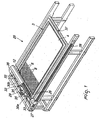
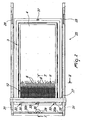
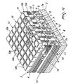
- the press comprises: an upper pressing surface 1 and a lower pressing surface 2, which are arranged substantially horizontally and face each other, and a part supporting tray 3, the bottom 4 of which forms a substantially horizontal supporting surface for the parts 5 to be clad.
- the part supporting tray 3 can be rested on the lower pressing surface 2 so that the parts 5 to be clad face the upper pressing surface 1.
- the part supporting tray 3 and the pressing surfaces 1 and 2 preferably have a rectangular plan shape.
- the bottom 4 of the part supporting tray 3 is crossed by a plurality of holes 6, which have a substantially vertical axis and are arranged in a grid, i.e., are uniformly mutually spaced along lines which are parallel to the perimetric sides of the part supporting tray 3, so as to occupy substantially the entire surface of the bottom 4 of the part supporting tray 3.
- the lower pressing surface 2 is provided with a plurality of actuation pins 7, which have a substantially vertical axis 7a and are arranged so as to correspond to the holes 6, so that by correctly positioning the part supporting tray 3 above the lower pressing surface 2, the holes 6 are each aligned with the hole axis aligned with the axis of a corresponding actuation pin 7.
- the actuation pins 7 are provided so as to have a vertical length which is variable as a function of the shape or contour of the parts 5 arranged on the part supporting tray 3 so as to be inserted, in their maximum-length condition, in the corresponding hole 6, providing supporting regions which are raised with respect to a supporting surface formed by the part supporting tray 3, as will become better apparent hereinafter, and make contact with the lower face of the parts 5 in regions which are spaced from the perimetric edge of the parts 5 or in order to not create (i.e. avoid creation of), in their minimum-length condition, said supporting regions which are raised with respect to said supporting surface.
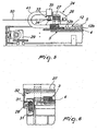
- Each actuation pin 7 is composed of a lower portion 8, which is fixed to the lower pressing surface 2 and whose vertical axis forms the axis 7a of the actuation pin 7, and of an upper portion 9, which is pivoted to the lower portion 8 about a horizontal pivoting axis 10.
- the upper portion 9 can rotate with respect to the lower portion 8 about the pivoting axis 10 in order to pass from an activation position, in which it provides the maximum-length condition for the actuation pin 7 by being aligned with the lower portion 8, to a deactivation position, in which it provides the minimum-length condition for the actuation pin 7 by being arranged substantially horizontally.
- Elastic means constituted by a spring 11 are interposed between the lower portion 8 and the upper portion 9 and stabilize the activation position and the deactivation position of the upper portion 9.
- the bottom 4 of the part supporting tray 3 is covered by a plurality of supporting pins 12, each of which is inserted in one of the holes 6 and can slide axially along the corresponding hole 6 with respect to the part supporting tray 3.
- each supporting pin 12 has a stem 12a, which is inserted coaxially in the corresponding hole 6 of the part supporting tray 3, and a head 12b, which preferably has a square plan shape, is connected to the stem 12a and is arranged above the bottom 4.
- the press comprises resetting means 13, which can be actuated on command in order to provide the transition of the upper portions 9 of the actuation pins 7 from the deactivation position to the activation position.
- the resetting means 13 comprise a plate 14, which is arranged on the lower pressing surface 2 and is crossed by holes having a vertical axis, each of which accommodates one of the actuation pins 7.
- the plate 14 has such a thickness as to contain only part of the lower portion 8 of the actuation pins 7 and can move on command along a vertical direction with respect to the lower pressing surface 2 from an inactive position, in which it rests on the lower pressing surface 2 and is arranged below the axes 10 about which the upper portions 9 are pivoted to the lower portions 8 of the actuation pins 7 in order to allow the transition of the upper portions 9 of the actuation pins 7 from the activation position to the deactivation position, to a resetting position, in which it is shifted upwardly with respect to the inactive position so as to provide the transition of the upper portion 9 of the actuation pins 7 from the deactivation position to the activation position.
- the vertical upward and downward movement of the plate 14 can be produced by fluid-operated actuators 15, for example pneumatic or hydraulic cylinders which have a vertical axis and are connected by means of their body below the lower pressing surface 2 and are connected to the plate 14 by means of the stem 15a of their piston, which passes through the lower pressing surface 2.
- fluid-operated actuators 15 for example pneumatic or hydraulic cylinders which have a vertical axis and are connected by means of their body below the lower pressing surface 2 and are connected to the plate 14 by means of the stem 15a of their piston, which passes through the lower pressing surface 2.
- actuation means 16 which comprise actuators 17 which are mounted on a supporting bar 18 which is oriented parallel to the shorter sides of the lower pressing surface 2.
- the supporting bar 18 is mounted so that it can slide on guides 19 which run parallel to the longer sides of the lower pressing surface 2.
- the actuators 17 are spaced one another so as to correspond to the spacing of the actuation pins 7 along a row which is parallel to the shorter sides of the lower pressing surface 2, and each of the actuators 17 is provided with an element 17a which can move on command from an active position, in which it interacts with the upper portion 9 of the actuation pins 7 during the translational motion of the supporting bar 18 along the guides 19, to an inactive position, in which it does not interact with the upper portion 9 of the actuation pins 7 during the translational motion of the supporting bar 18 along the guides 19, or vice versa.
- the actuators 17 can be constituted by conventional actuators, in particular electromagnetic actuators provided with an element 17a which can move vertically in order to interfere or not interfere with the upper portion 9 of the actuation pins 7 which are in the activation position.
- the movement of the supporting bar 18 along the guides 19 is actuated by a gearmotor 20, which by means of two shafts 21 a, 21b is connected to pulleys whose axis is oriented horizontally and transversely to the guides 19, not shown in the figures, which in turn are each connected to a corresponding guiding pulley by means of a corresponding belt 22, the two portions of which are parallel to the guides 19.
- the supporting bar 18 is fixed, at its longitudinal ends, to a portion of the belts 22 by means of L-shaped elements 23 so that the actuation of the gearmotor 20 produces the movement of the supporting bar 18 along the guides 19 in one direction or the other according to the requirements.
- the actuation means 16 are functionally connected to detection means 24 for detecting the shape or contour of the parts 5 to be clad, so that the transition of the upper portion 9 of the actuation pins 7 from the activation position to the deactivation position is performed as a function of the shape of the parts 5 to be clad.
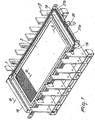
- a detection station 25 in which the part supporting tray 3 is parked before it is inserted between the pressing surfaces 1 and 2.
- the detection means 24 which comprise preferably conventional optical detectors 26, which are mounted on a supporting bar 27 which is parallel to the shorter sides of the part supporting tray 3, arranged in the detection station 25, and can move on command along guides 28 which run parallel to the longer sides of the part supporting tray 3.
- the movement of the supporting bar 27 along the guides 28 is performed in a manner which is similar to what has been described as regards the supporting bar 18 of the actuation means 16, i.e., by means of a gearmotor 29, which by means of two shafts 30a, 30b is connected to pulleys whose axis is oriented horizontally and transversely with respect to the guides 28, not shown in the figures, which in turn are each connected to a corresponding guiding pulley by means of a corresponding belt 31, the two portions of which are parallel to the guides 28.
- the supporting bar 27 is fixed, at its longitudinal ends, to a portion of the belts 31 by means of L-shaped elements 32, so that the actuation of the gearmotor 29 produces the movement of the supporting bar 27 along the guides 28 in one direction or the other according to the requirements.
- the supporting bar 27, which supports the detection means 24, is provided with grip means 33 for the cladding sheet 50 in order to lay the cladding sheet 50 on the parts 5 deposited on the part supporting tray 3 during the translational motion of the supporting bar 27 along the guides 28, while the contour of the parts 5 to be clad is detected.
- the grip means 33 can be constituted by clamps 34, which are mounted on the supporting bar 27 and are actuated for example by pneumatic actuators 35, which are also mounted on the supporting bar 27.
- the press is completed by conventional means, not shown for the sake of simplicity, for moving the part supporting tray 3 in order to perform sequentially its placement in the detection station 25, its insertion between the pressing surfaces 1 and 2, and its extraction from the pressing surfaces, and by movement means, also of a known type and not shown for the sake of simplicity, for moving vertically one pressing surface with respect to the other.
- centering means constituted by pins 36 which have a vertical axis, are rigidly coupled to the lower pressing surface 2 and are designed to engage holes 37 provided in a border of the part supporting tray 3 at its shorter sides.
- the part supporting tray 3 is provided with a raised edge 38, which is designed to mate with a corresponding edge 39 of the upper pressing surface so as to lock between said edges the cladding sheet 50 when one pressing surface is moved toward the other.
- the press according to the invention can be provided with means, of a known type and not shown, for producing vacuum between the cladding sheet 50 and the underlying region of the part supporting tray 3 once said tray has been inserted between the pressing surfaces 1 and 2 and the cladding sheet 50 has been locked between the edges 38 and 39 in order to force the adhesion of the cladding sheet 50 to the upper face and to the lateral faces of the parts 5 to be clad.
- the part supporting tray 3 is loaded with the parts 5 to be clad, which are deposited on the head 12b of the supporting pins 12, and is positioned in the detection station 25.
- the contour of the parts 5 to be clad is detected in the detection station 25 by making the supporting bar 27 slide along the guides 28 so that the detection means 24 can detect precisely the shape of the parts 5.
- the cladding sheet 50 is applied over the parts 5 to be clad.
- the detection performed by the detection means 24 is transmitted, in a per se known manner, to an electronic control and actuation element, which supervises the operation of the press, actuates the translational motion of the supporting bar 18 along the guides 19 and actuates the actuators 17 so that they interact exclusively with the upper portion 9 of the actuation pins 7, which are designed to be aligned with the supporting pins 12 of the part supporting tray 3 which are covered, or covered only partially, by the parts 5 to be clad.
- the part supporting tray 3 is arranged above the lower pressing surface 2.
- the movement of one pressing surface toward the other performed for example by lifting the lower pressing surface 2 towards the upper pressing surface 1 or by lowering the part supporting tray 3 and the upper pressing surface 1, produces the insertion of the upper portion 9 of the actuation pins 7 that has remained in the activation position in the holes 6 of the bottom 4 of the part supporting tray 3, with consequent rise of the supporting pins 12 and of the parts 5 deposited thereon with respect to the supporting surface formed by the heads 12b of the supporting pins 12 which are not raised.
- the lifting of the supporting pins 12 in practice produces supporting shapes which keep the parts 5 raised with respect to the supporting surface on which they were located prior to the approach of the pressing surfaces, i.e., with respect to the plane formed by the supporting pins 12 that have not been raised because they are aligned with the upper portions 9 of the actuation pins 7 which have been moved into the deactivation position by the intervention of the actuators 17.
- the parts 5 to be clad are supported in regions which are spaced from their peripheral profile.
- the cladding of the parts 5 is completed by making the cladding sheet 50 adhere to the upper face and to the lateral faces of the parts 5, for example by subjecting to suction the region between the bottom 4 of the part supporting tray 3 and the cladding sheet 50, which is heated, in a per se known manner, by the upper pressing surface 1.
- the pressing surfaces 1 and 2 are moved mutually apart and the part supporting tray 3 is moved outside the pressing surfaces 1 and 2 in order to allow the unloading of the clad parts 5. from the part supporting tray 3.
- the plate 14 is raised so as to return the upper portion 9 of the actuation pins 7, previously brought to the deactivation position, to the activation position.
- the part supporting tray 3 and the supporting pins 12 since the creation of the supporting shapes is almost entirely entrusted to the actuation pins 7 located on the lower pressing surface 2, can have an extremely simple structure and therefore be manufactured with distinctly lower costs than those required by part supporting trays of known types of presses with automated composition of the shapes for supporting the parts to be clad. Moreover, thanks to the fact that the actuation pins 7 are arranged on the lower pressing surface 2 and therefore are disengaged from the movement of the part supporting tray or trays 3, there is less danger of damage of the actuation pins 7 following accidental impacts.
- the press according to the invention fully achieves the intended aim, since it provides an automated composition of the shapes for supporting the parts to be clad and can be equipped with a plurality of part supporting trays, so as to ensure high productivity, with distinctly lower costs than those required by known types of presses with automated composition of the supporting shapes.
- Another advantage of the press according to the invention is that it can be connected functionally to machines arranged upstream, along the part production line, so as to optimize the arrangement and combination of the parts on the part supporting tray with their production in order to minimize the waste of the cladding sheet.
- the materials used, as well as the dimensions, may be any according to requirements and to the state of the art.
Landscapes
- Engineering & Computer Science (AREA)
- Mechanical Engineering (AREA)
- Manufacturing & Machinery (AREA)
- Life Sciences & Earth Sciences (AREA)
- Physics & Mathematics (AREA)
- Fluid Mechanics (AREA)
- Wood Science & Technology (AREA)
- Forests & Forestry (AREA)
- Casting Or Compression Moulding Of Plastics Or The Like (AREA)
- Dry Formation Of Fiberboard And The Like (AREA)
Claims (14)
- Eine Presse für die mehrseitige Beschichtung von Teilen mit Material in Form von Folien, insbesondere für die Beschichtung von Holzelementen von Möbeln oder Türen oder Fenstern, mit einer Kunststofffolie, Folgendes umfassend: eine obere Pressoberfläche (1) und eine untere Pressoberfläche (2), die einander gegenüberliegen, und ein Teile tragendes Tablett (3), das mit einem Boden (4) versehen ist, welcher eine im Wesentlichen horizontale tragende Oberfläche für die zu beschichtenden Teile (5) bildet und welcher auf die untere Pressoberfläche (2) aufgelegt werden kann, dadurch gekennzeichnet, dass der Boden (4) des Teile tragenden Tabletts (3) von einer Vielzahl von Löchern (6) gekreuzt wird, die eine im Wesentlichen vertikale Achse haben und in einem Gitter angeordnet sind, und dadurch, dass die untere Pressoberfläche (2) mit einer Vielzahl von Betätigungsstiften (7) ausgestattet ist, die eine im Wesentlichen vertikale Achse (7a) haben und so angeordnet sind, dass sie den Löchern (6) des Teile tragenden Tabletts (3) entsprechen, wobei das Teile tragende Tablett (3) so angeordnet werden kann, dass die Achsen seiner Löcher (6) mit den Achsen (7a) der Betätigungsstifte (7) ausgerichtet sind, und die Betätigungsstifte (7) eine vertikale Länge haben, die variabel ist, als eine Funktion der Kontur der Teile (5), die auf dem Teile tragenden Tablett (3) angeordnet werden, um im Zustand ihrer maximalen Länge durch die Löcher (6) geführt zu werden, wobei die Betätigungsstifte Stützbereiche für die Teile (5) bestimmen, die mit Bezug auf eine im Wesentlichen horizontale tragende Oberfläche angehoben sind, welche von dem Teile tragenden Tablett (3) gebildet wird, wobei die Stützbereiche in Kontakt mit der unteren Fläche der Teile (5) in Bereichen stehen, welche von der perimetrischen Kante der Teile (5) beabstandet sind, oder so, dass die Erzeugung der angehobenen Stützbereiche im Zustand ihrer Mindestlänge verhindert wird;
wobei die Betätigungsstifte (7) einen unteren Abschnitt (8) haben, der eine vertikale Achse (7a) hat und mit der unteren Pressoberfläche (2) verbunden ist, und einen oberen Abschnitt (9) hat, der gelenkig mit dem unteren Abschnitt (8) verbunden ist und sich in Bezug zu dem unteren Abschnitt (8) um eine Drehachse (10) drehen kann, um von einer Aktivierungsposition, in welcher der obere Abschnitt (9) mit dem unteren Abschnitt (8) fluchtet, wodurch der Zustand der Maximallänge für den Betätigungsstift (7) hergestellt wird, in eine Deaktivierungsposition überzugehen, in welcher der obere Abschnitt (9) im Wesentlichen horizontal angeordnet ist, was den Zustand der Mindestlänge für den Betätigungsstift (7) herstellt;
wobei die Presse weiter Rückstellmittel (13) umfasst, welche auf Befehl betätigt werden können, um den Übergang der oberen Abschnitte (9) der Betätigungsstifte (7) aus der Deaktivierungsposition in die Aktivierungsposition durchzuführen;
wobei das Rückstellmittel (13) eine Platte (14) umfasst, die auf der unteren Pressoberfläche (2) angeordnet ist und von Löchern gekreuzt wird, welche eine vertikale Achse haben, wobei jedes Loch eines der Betätigungsstifte (7) aufnimmt und die Platte (14) eine Dicke hat, welche ausgebildet ist, um nur einen Teil des unteren Abschnitts der Betätigungsstifte (7) zu enthalten, wobei die Platte (14) auf Befehl entlang einer vertikalen Richtung zu der unteren Pressoberfläche (2) beweglich ist, und zwar aus einer inaktiven Position, in welcher sie auf der unteren Pressoberfläche (2) ruht und unterhalb der Achsen (10) angeordnet ist, um welche die oberen Abschnitte (9) gelenkig mit den unteren Abschnitten (8) der Betätigungsstifte (7) verbunden sind, um den Übergang der oberen Abschnitte (9) der Betätigungsstifte (7) aus der Aktivierungsposition in die Deaktivierungsposition zu ermöglichen, in eine Rückstellposition, in der sie in Bezug zu der inaktiven Position aufwärts bewegt wird, um den Übergang des oberen Abschnitts (9) der Betätigungsstifte (7) aus der Deaktivierungsposition in die Aktivierungsposition zu veranlassen. - Die Presse gemäß Anspruch 1, dadurch gekennzeichnet, dass sie elastische Mittel (11) umfasst, die zwischen dem unteren Abschnitt (8) und dem oberen Abschnitt (9) des Betätigungsstifts (7) angeordnet sind, um die Aktivierungsposition und die Position des oberen Abschnitts (9) zu stabilisieren.
- Die Presse gemäß einem oder mehreren der obigen Ansprüche, dadurch gekennzeichnet, dass die untere Pressoberfläche (2), die obere Pressoberfläche (1) und das Teile tragende Tablett (3) eine im Wesentlichen rechteckige flache Form haben, wobei die Vielzahl von Löchern (6) entlang den Linien eines Gitters angeordnet sind, das parallel zu den Seiten des Teile tragenden Tabletts (3) liegt.
- Die Presse gemäß einem oder mehreren der obigen Ansprüche, dadurch gekennzeichnet, dass der Boden (4) des Tabletts (3) von einer Vielzahl von Stützstiften (12) bedeckt ist, die jeweils in eines der Löcher (6) eingesetzt werden und axial zu dem Teile tragenden Tablett (3) gleiten können.
- Die Presse gemäß Anspruch 4, dadurch gekennzeichnet, dass die Stützstifte (12) einen Schaft (12a) umfassen, der in das entsprechende Loch (6) des Bodens (4) des Teile tragenden Tabletts (3) eingesetzt wird, und einen Kopf (12b), der mit dem Schaft (12a) verbunden ist und größere Maße hat, wobei der Kopf (12b) über dem Boden (4) des Teile tragenden Tabletts (3) angeordnet ist und im Zustand zum Ruhen auf dem Boden (4) des Teile tragenden Tabletts (3) die tragende Oberfläche bildet.
- Die Presse gemäß Anspruch 5, dadurch gekennzeichnet, dass der Kopf (12b) der Stützstifte (12) eine quadratische flache Form hat,
- Die Presse gemäß einem oder mehreren der obigen Ansprüche, dadurch gekennzeichnet, dass sie Betätigungsmittel (16) umfasst, die auf Befehl auf den oberen Abschnitt (9) der Betätigungsstifte (7) einwirken, um ihren Übergang aus der Aktivierungsposition in die Deaktivierungsposition herbeizuführen.
- Die Presse gemäß einem oder mehreren der obigen Ansprüche, dadurch gekennzeichnet, dass sie Mittel (24) zur Erkennung der Kontur der zu beschichtenden Teile (5) umfasst.
- Die Presse gemäß Anspruch 8, dadurch gekennzeichnet, dass die Mittel (24) zur Erkennung der Kontur der zu beschichtenden Teile (5) funktionell mit den Betätigungsmitteln (16) verbunden sind, zwecks Intervention der Betätigungsmittel mit dem oberen Abschnitt (9) der Betätigungsstifte (7) entsprechend der Kontur der zu beschichtenden Teile (5).
- Die Presse gemäß einem oder mehreren der Ansprüche 8-9, dadurch gekennzeichnet, dass die Mittel (24) zur Erkennung der Kontur der zu beschichtenden Teile (5) an einer Erkennungsstation (25) angeordnet sind, welche außerhalb der unteren Pressoberfläche (2) und der oberen Pressoberfläche (1) angeordnet ist.
- Die Presse gemäß einem oder mehreren der Ansprüche 8-10, dadurch gekennzeichnet, dass die Mittel (24) zur Erkennung der Kontur der zu beschichtenden Teile (5) optische Erkennungsmittel (26) umfassen, welche auf einer Stützstange (27) montiert sind, die parallel zu den kürzeren Seiten des Teile tragenden Tabletts (3) ausgerichtet ist, das in der Erkennungsstation (25) angeordnet ist, wobei die Stange (27) zum Stützen der Erkennungsmittel (24) auf Befehl entlang Führungen (28) bewegt werden kann, die parallel zu den längeren Seiten des Teile tragenden Tabletts (3) verlaufen, das in der Erkennungsstation (25) angeordnet ist.
- Die Presse gemäß Anspruch 11, dadurch gekennzeichnet, dass die Stange (27) zum Stützen der Erkennungsmittel (24) mit Greifmitteln (33) ausgestattet ist.
- Die Presse gemäß einem oder mehreren der Ansprüche 7-12, dadurch gekennzeichnet, dass die Betätigungsmittel (16) Betätigungsglieder (17) umfassen, die auf einer Stützstange (18) montiert sind, welche so montiert ist, dass sie auf Führungen (19) gleiten kann, die parallel zu den längeren Seiten der unteren Pressoberfläche (2) verlaufen, wobei die Stange (18) zum Stützen der Betätigungsmittel (16) parallel zu den kürzeren Seiten der unteren Pressoberfläche (2) ausgerichtet ist und die Betätigungsglieder (17) voneinander beabstandet sind, so dass sie dem Abstand der Betätigungsstifte (7) entlang einer Reihe entsprechen, welche parallel zu den kürzeren Seiten der unteren Pressoberfläche (2) ist, wobei jedes der Betätigungsglieder (17) mit einem Element (17a) ausgestattet ist, das sich auf Befehl aus einer aktiven Position, in der es mit dem oberen Abschnitt (9) der Betätigungsstifte (7) während der translatorischen Bewegung der Stange (18) zusammenwirkt, um die Betätigungsmittel (16) entlang den Führungen (19) zu stützen, in eine inaktive Position bewegen kann, in der es während der translatorischen Bewegung der Stützstange (18) der Betätigungsmittel (16) entlang den Führungen (19) nicht mit dem oberen Abschnitt (9) der Betätigungsstifte (7) zusammenwirkt, oder umgekehrt.
- Die Presse gemäß einem oder mehreren der obigen Ansprüche, dadurch gekennzeichnet, dass sie Mittel zum Bewegen des Teile tragenden Tabletts (3), um das Tablett (3) zwischen die untere Pressoberfläche (2) und die obere Pressoberfläche (1) einzufügen, und Mittel (36) umfasst, um das Teile tragende Tablett (3) in Bezug zu der unteren Pressoberfläche (2) zu zentrieren.
Applications Claiming Priority (1)
| Application Number | Priority Date | Filing Date | Title |
|---|---|---|---|
| ITMI20052274 ITMI20052274A1 (it) | 2005-11-28 | 2005-11-28 | Pressa per il rivestimento multilaterale di pezzi con materiale in foglio particolarmente per il rivestimento di componenti di mobili o di serramenti in legno con un foglio in materiale sintetico |
Publications (4)
| Publication Number | Publication Date |
|---|---|
| EP1790464A2 EP1790464A2 (de) | 2007-05-30 |
| EP1790464A3 EP1790464A3 (de) | 2008-08-13 |
| EP1790464B1 EP1790464B1 (de) | 2010-10-13 |
| EP1790464B2 true EP1790464B2 (de) | 2015-12-16 |
Family
ID=37758765
Family Applications (1)
| Application Number | Title | Priority Date | Filing Date |
|---|---|---|---|
| EP06023659.3A Active EP1790464B2 (de) | 2005-11-28 | 2006-11-14 | Presse für die mehrseitige Beschichtung von Teilen mit Blattmaterial, insbesondere für die Beschichtung von Holzelementen in Möbeln, Türen und Fenstern mit einer Kunststofffolie |
Country Status (4)
| Country | Link |
|---|---|
| EP (1) | EP1790464B2 (de) |
| DE (1) | DE602006017492D1 (de) |
| ES (1) | ES2354222T5 (de) |
| IT (1) | ITMI20052274A1 (de) |
Families Citing this family (3)
| Publication number | Priority date | Publication date | Assignee | Title |
|---|---|---|---|---|
| IT1399938B1 (it) * | 2010-04-30 | 2013-05-09 | Saom S R L | Pressa per il rivestimento tridimensionale di pezzi sagomati mediante applicazione di materiale laminare |
| ES2613076B1 (es) * | 2017-02-07 | 2018-02-28 | Cermotec S.L. | Sistema y método de revestimiento de ranuras en piezas de carpintería |
| CN112140254B (zh) * | 2020-09-23 | 2021-05-14 | 湖南宏森新材料科技有限责任公司 | 一种木板对齐上胶的装置 |
Family Cites Families (6)
| Publication number | Priority date | Publication date | Assignee | Title |
|---|---|---|---|---|
| DE19611754C2 (de) | 1996-03-25 | 1998-03-19 | Wemhoener Heinrich Gmbh Co | Beschichtungspresse |
| US6103012A (en) * | 1997-03-18 | 2000-08-15 | Heinrich Wemhoener Gmbh & Co. Kg Maschinenfabrik | Coating press |
| DE29707883U1 (de) * | 1997-05-02 | 1997-08-07 | Heinrich Wemhöner GmbH & Co KG Maschinenfabrik, 32052 Herford | Beschichtungspresse |
| AU7627400A (en) | 1999-07-29 | 2001-02-19 | Antonio Tadeu Candido | Raster pin system for use with thermoforming presses |
| IT1317645B1 (it) | 2000-05-18 | 2003-07-15 | Italpresse Eng Spa | Dispositivo per la movimentazione e il posizionamento di oggetti,particolarmente del tipo pannelli per la produzione di componenti |
| ITMI20021066A1 (it) | 2002-05-17 | 2003-11-17 | Italpresse Eng Spa | Procedimento e dispositivo per l'azzeramento della posizione dei pioli in vassoi con pioli per il supporto di oggetti particolarmente del t |
-
2005
- 2005-11-28 IT ITMI20052274 patent/ITMI20052274A1/it unknown
-
2006
- 2006-11-14 DE DE200660017492 patent/DE602006017492D1/de active Active
- 2006-11-14 EP EP06023659.3A patent/EP1790464B2/de active Active
- 2006-11-14 ES ES06023659.3T patent/ES2354222T5/es active Active
Also Published As
| Publication number | Publication date |
|---|---|
| EP1790464A3 (de) | 2008-08-13 |
| ES2354222T3 (es) | 2011-03-11 |
| EP1790464A2 (de) | 2007-05-30 |
| DE602006017492D1 (de) | 2010-11-25 |
| ES2354222T5 (es) | 2016-03-15 |
| ITMI20052274A1 (it) | 2007-05-29 |
| EP1790464B1 (de) | 2010-10-13 |
Similar Documents
| Publication | Publication Date | Title |
|---|---|---|
| AU710703B2 (en) | Apparatus for and process of hot pressing boards | |
| US20110011232A1 (en) | Automatic machine for punching and cutting wheel rims | |
| EP1790464B1 (de) | Presse für die mehrseitige Beschichtung von Teilen mit Blattmaterial, insbesondere für die Beschichtung von Holzelementen in Möbeln, Türen und Fenstern mit einer Kunststofffolie | |
| CN113581811B (zh) | 一种家具封边机的送料系统 | |
| KR102152102B1 (ko) | 파렛트용 패드 인쇄장치 | |
| KR101627557B1 (ko) | 프레스 장치 및 프레스 금형 교체용 지그 | |
| EP1160074B1 (de) | Vorrichtung zum Positionieren von Werkstücken in Beschichtungspressen | |
| KR101574877B1 (ko) | 판형상 피반송물의 수도 방법, 수도 장치 및 패턴 형성 장치 | |
| KR20110058963A (ko) | 플레이트 벤딩 성형장치 | |
| EP0593429B1 (de) | Apparat zum beschichten der oberfläche und der seitenkanten einer platte aus holz oder ähnlichem material mit einer wärmeverformbaren folie | |
| JP3609625B2 (ja) | 合成樹脂シートを成形して裁断する成形品の製造装置 | |
| CN211197727U (zh) | 随行工装分料及二次定位装置 | |
| KR102148626B1 (ko) | 판재의 성형 및 건조 장치 | |
| EP1475204B1 (de) | Werkzeugmaschine zur Bearbeitung von Holzplatten oder dergleichen | |
| CN118876635A (zh) | 一种门面压花生产线 | |
| CN211732972U (zh) | 一种用于板材检验的翻转装置 | |
| KR101305416B1 (ko) | 가구용 패널 투입방법 | |
| KR100851359B1 (ko) | 브레이크 패드 제조시스템용 브레이크 패드의 부품이송장치 | |
| US2973025A (en) | Apparatus for making surface shapes covered with formed sheet material | |
| EP3685978A1 (de) | Vorrichtung und verfahren zum panelen herstellung | |
| TWM626224U (zh) | 智能網版印刷系統 | |
| EP2674269B1 (de) | Zuführer von Platten für Maschinen zur Montage von Paletten mit umkreisendem Sockel | |
| KR102293733B1 (ko) | 기판 정렬 장치 및 그것을 이용한 기판 정렬 방법 | |
| CN112744552A (zh) | 一种随行工装分料及二次定位装置 | |
| KR101792802B1 (ko) | 반도체 소켓 가압용 블레이드 체인저 |
Legal Events
| Date | Code | Title | Description |
|---|---|---|---|
| PUAI | Public reference made under article 153(3) epc to a published international application that has entered the european phase |
Free format text: ORIGINAL CODE: 0009012 |
|
| AK | Designated contracting states |
Kind code of ref document: A2 Designated state(s): AT BE BG CH CY CZ DE DK EE ES FI FR GB GR HU IE IS IT LI LT LU LV MC NL PL PT RO SE SI SK TR |
|
| AX | Request for extension of the european patent |
Extension state: AL BA HR MK YU |
|
| PUAL | Search report despatched |
Free format text: ORIGINAL CODE: 0009013 |
|
| AK | Designated contracting states |
Kind code of ref document: A3 Designated state(s): AT BE BG CH CY CZ DE DK EE ES FI FR GB GR HU IE IS IT LI LT LU LV MC NL PL PT RO SE SI SK TR |
|
| AX | Request for extension of the european patent |
Extension state: AL BA HR MK RS |
|
| 17P | Request for examination filed |
Effective date: 20090116 |
|
| AKX | Designation fees paid |
Designated state(s): DE ES IT |
|
| GRAP | Despatch of communication of intention to grant a patent |
Free format text: ORIGINAL CODE: EPIDOSNIGR1 |
|
| GRAS | Grant fee paid |
Free format text: ORIGINAL CODE: EPIDOSNIGR3 |
|
| GRAA | (expected) grant |
Free format text: ORIGINAL CODE: 0009210 |
|
| AK | Designated contracting states |
Kind code of ref document: B1 Designated state(s): DE ES IT |
|
| REF | Corresponds to: |
Ref document number: 602006017492 Country of ref document: DE Date of ref document: 20101125 Kind code of ref document: P |
|
| REG | Reference to a national code |
Ref country code: ES Ref legal event code: FG2A Effective date: 20110301 |
|
| PLBI | Opposition filed |
Free format text: ORIGINAL CODE: 0009260 |
|
| PLAX | Notice of opposition and request to file observation + time limit sent |
Free format text: ORIGINAL CODE: EPIDOSNOBS2 |
|
| 26 | Opposition filed |
Opponent name: ROBERT BUERKLE GMBH Effective date: 20110712 |
|
| REG | Reference to a national code |
Ref country code: DE Ref legal event code: R026 Ref document number: 602006017492 Country of ref document: DE Effective date: 20110712 |
|
| PLAF | Information modified related to communication of a notice of opposition and request to file observations + time limit |
Free format text: ORIGINAL CODE: EPIDOSCOBS2 |
|
| PLBB | Reply of patent proprietor to notice(s) of opposition received |
Free format text: ORIGINAL CODE: EPIDOSNOBS3 |
|
| RIC2 | Information provided on ipc code assigned after grant |
Ipc: B30B 5/02 20060101AFI20141118BHEP Ipc: B23Q 1/03 20060101ALI20141118BHEP Ipc: B29C 63/00 20060101ALI20141118BHEP Ipc: B27D 1/08 20060101ALI20141118BHEP |
|
| PUAH | Patent maintained in amended form |
Free format text: ORIGINAL CODE: 0009272 |
|
| STAA | Information on the status of an ep patent application or granted ep patent |
Free format text: STATUS: PATENT MAINTAINED AS AMENDED |
|
| 27A | Patent maintained in amended form |
Effective date: 20151216 |
|
| AK | Designated contracting states |
Kind code of ref document: B2 Designated state(s): DE ES IT |
|
| REG | Reference to a national code |
Ref country code: DE Ref legal event code: R102 Ref document number: 602006017492 Country of ref document: DE |
|
| REG | Reference to a national code |
Ref country code: ES Ref legal event code: DC2A Ref document number: 2354222 Country of ref document: ES Kind code of ref document: T5 Effective date: 20160315 |
|
| REG | Reference to a national code |
Ref country code: DE Ref legal event code: R082 Ref document number: 602006017492 Country of ref document: DE Representative=s name: SCHIEBER - FARAGO PATENTANWAELTE, DE Ref country code: DE Ref legal event code: R082 Ref document number: 602006017492 Country of ref document: DE Representative=s name: FARAGO PATENTANWALTSGESELLSCHAFT MBH, DE |
|
| REG | Reference to a national code |
Ref country code: DE Ref legal event code: R082 Ref document number: 602006017492 Country of ref document: DE Representative=s name: SCHIEBER - FARAGO PATENTANWAELTE, DE |
|
| PGFP | Annual fee paid to national office [announced via postgrant information from national office to epo] |
Ref country code: IT Payment date: 20250922 Year of fee payment: 20 |
|
| PGFP | Annual fee paid to national office [announced via postgrant information from national office to epo] |
Ref country code: DE Payment date: 20251118 Year of fee payment: 20 |
|
| PGFP | Annual fee paid to national office [announced via postgrant information from national office to epo] |
Ref country code: ES Payment date: 20251212 Year of fee payment: 20 |