EP1790933B1 - Tubes Coaxiales, en particulier pour un échangeur de chaleur - Google Patents
Tubes Coaxiales, en particulier pour un échangeur de chaleur Download PDFInfo
- Publication number
- EP1790933B1 EP1790933B1 EP20060022999 EP06022999A EP1790933B1 EP 1790933 B1 EP1790933 B1 EP 1790933B1 EP 20060022999 EP20060022999 EP 20060022999 EP 06022999 A EP06022999 A EP 06022999A EP 1790933 B1 EP1790933 B1 EP 1790933B1
- Authority
- EP
- European Patent Office
- Prior art keywords
- tube
- concentric
- concentric tube
- tube according
- fins
- Prior art date
- Legal status (The legal status is an assumption and is not a legal conclusion. Google has not performed a legal analysis and makes no representation as to the accuracy of the status listed.)
- Not-in-force
Links
- 239000003507 refrigerant Substances 0.000 claims description 17
- 238000004378 air conditioning Methods 0.000 claims description 5
- 229910000838 Al alloy Inorganic materials 0.000 claims description 3
- 230000009172 bursting Effects 0.000 description 4
- 238000001816 cooling Methods 0.000 description 4
- 239000000463 material Substances 0.000 description 4
- 210000002435 tendon Anatomy 0.000 description 2
- 238000005452 bending Methods 0.000 description 1
- 239000003795 chemical substances by application Substances 0.000 description 1
- 230000007797 corrosion Effects 0.000 description 1
- 238000005260 corrosion Methods 0.000 description 1
- 230000001419 dependent effect Effects 0.000 description 1
- 239000012530 fluid Substances 0.000 description 1
Images


Classifications
-
- F—MECHANICAL ENGINEERING; LIGHTING; HEATING; WEAPONS; BLASTING
- F28—HEAT EXCHANGE IN GENERAL
- F28D—HEAT-EXCHANGE APPARATUS, NOT PROVIDED FOR IN ANOTHER SUBCLASS, IN WHICH THE HEAT-EXCHANGE MEDIA DO NOT COME INTO DIRECT CONTACT
- F28D7/00—Heat-exchange apparatus having stationary tubular conduit assemblies for both heat-exchange media, the media being in contact with different sides of a conduit wall
- F28D7/10—Heat-exchange apparatus having stationary tubular conduit assemblies for both heat-exchange media, the media being in contact with different sides of a conduit wall the conduits being arranged one within the other, e.g. concentrically
- F28D7/106—Heat-exchange apparatus having stationary tubular conduit assemblies for both heat-exchange media, the media being in contact with different sides of a conduit wall the conduits being arranged one within the other, e.g. concentrically consisting of two coaxial conduits or modules of two coaxial conduits
-
- F—MECHANICAL ENGINEERING; LIGHTING; HEATING; WEAPONS; BLASTING
- F28—HEAT EXCHANGE IN GENERAL
- F28F—DETAILS OF HEAT-EXCHANGE AND HEAT-TRANSFER APPARATUS, OF GENERAL APPLICATION
- F28F1/00—Tubular elements; Assemblies of tubular elements
- F28F1/10—Tubular elements and assemblies thereof with means for increasing heat-transfer area, e.g. with fins, with projections, with recesses
- F28F1/40—Tubular elements and assemblies thereof with means for increasing heat-transfer area, e.g. with fins, with projections, with recesses the means being only inside the tubular element
-
- F—MECHANICAL ENGINEERING; LIGHTING; HEATING; WEAPONS; BLASTING
- F28—HEAT EXCHANGE IN GENERAL
- F28F—DETAILS OF HEAT-EXCHANGE AND HEAT-TRANSFER APPARATUS, OF GENERAL APPLICATION
- F28F13/00—Arrangements for modifying heat-transfer, e.g. increasing, decreasing
- F28F13/06—Arrangements for modifying heat-transfer, e.g. increasing, decreasing by affecting the pattern of flow of the heat-exchange media
- F28F13/12—Arrangements for modifying heat-transfer, e.g. increasing, decreasing by affecting the pattern of flow of the heat-exchange media by creating turbulence, e.g. by stirring, by increasing the force of circulation
Definitions
- the invention relates to a coaxial tube or a tube-in-tube arrangement according to the preamble of claim 1.
- EP-A1-0550845 shows such a coaxial tube.
- From the EP 1 202 016 A2 is a one-piece heat exchanger tube with a multi-chamber profile known, according to which a plurality of outer channels are provided around a central channel.
- the outer channels are divided by intermediate walls which extend in the radial direction.
- wave-like projections are provided, which extend slightly into the central channel. These projections serve to reduce the cross-sectional area and thus increase the flow velocity.
- the projections may also be helical, wherein constant, changing or changing slopes may be provided.
- the inner channel is used in this heat exchanger tube as the high pressure side, the outer channels as the low pressure side.
- a coaxial tube or a tube-in-tube arrangement for the separate line of at least two media, which is preferably refrigerant, wherein at least one and in a cross-sectional area in the coaxial tube or the tube-in-tube arrangement
- at most sixteen, more preferably at most twelve turbulence generators are provided, which are arranged in the inner region of the inner tube. The turbulence generators cause the boundary layer on the wall of the inner tube to be disturbed and thereby reduced, whereby the heat exchange and thereby the performance of the heat exchanger is improved.
- the turbulence generators are preferably arranged in the high-pressure region, which is usually provided in the inner region. However, it is also a twisted arrangement of high and low pressure area possible, i. the low pressure area is inside, the high pressure area outside.
- pipe is to be interpreted in the following very broad and refers not only to round cross-sections, but in particular also oval, rounded rectangular or any other cross-sections.
- the pipe may also be two tubes arranged inside one another which have no direct connections (tube-in-tube arrangement).
- positioning elements for the inner tube may be provided in the outer tube, such as provided on the outer and / or inner tube, radially inwardly or outwardly projecting ribs to optionally ensure a coaxial arrangement.
- the arrangement of the inner tube or of the inner region in the outer tube is preferably coaxial, but does not have to be, so that eccentric arrangements are also possible.
- several inner tubes may be provided, which are connected by means of several sleeves.
- the inner tube may also be soldered or otherwise connected to the outer tube in the contact regions.
- the turbulence generator is preferably formed by a helix extending in the longitudinal direction of the coaxial tube or the tube-in-tube arrangement.
- the helix is particularly preferably a round tube helix, wherein a gap is provided between the helix and the inner wall.
- the difference of the inner diameter of the inner tube and the coil width is preferably 0.2 to 1 mm, so that the coil does not jam in the event of bending of the tube.
- the helix preferably does not extend over the entire length of the tube but is in particular about 20 mm shorter, but is preferably at least about half as long as the tube, minus about 20 mm.
- the pitch of the helix is preferably 15 to 40 mm.
- At least one, in particular at least four, and a maximum of twelve inner ribs may be provided in the inner tube, alternatively or with a corresponding design, also in conjunction with a helix.
- the inner ribs may extend in the radial direction to the central longitudinal axis, but they may also be designed to extend obliquely to the radial direction.
- the inner ribs preferably have a rib thickness of 0.1 to 0.2 mm, so they are thin compared to the other wall thicknesses of the tube educated.
- the rib height of the inner ribs is preferably 0.5 to 1.5 mm with an inner diameter of the inner tube of 4 to 8 mm.
- the inner ribs are preferably arranged distributed in equidistant intervals over the inner circumference of the inner tube. However, it is also an uneven distribution, as well as a different rib height, possible.
- a turbulence generator is also at least one, in particular two or three webs in the inner tube in question. Of course, in particular four, five, six, seven, eight, nine or ten bars are conceivable.
- the web can in this case be designed to extend in the radial direction, as well as in any other way (i.e., as another tendon). If a plurality of webs are provided, they may preferably intersect in the longitudinal center axis of the pipe and subdivide the inner area into a plurality of subregions, wherein overflow openings may also be provided in the webs.
- the at least one web preferably has a web thickness of 0.2 to 0.6 mm, so it is preferably thinner than the outer and inner wall of the tube.
- the outer diameter of the outer tube is preferably 10 to 20 mm, in particular 12 to 18 mm.
- the inner diameter of the inner tube is preferably 3 to 10 mm, in particular 4 to 8 mm.
- the thickness of ribs or webs between the inner and outer tubes is preferably 0.3 to 1.1 mm, in particular 0.5 to 1.0 mm.
- the inlet openings of the two media are arranged on different sides of the coaxial tube or the tube-in-tube arrangement, so that the coaxial tube or the tube-in-tube arrangement is flowed through in countercurrent operation.
- the outer region, in which preferably the low-pressure medium flows, is preferably in at least six, in particular at least eight sub-channels and a maximum of twenty, preferably divided into a maximum of sixteen sub-channels.
- the wall thickness of the outer wall is preferably greater than or equal to the wall thickness of the wall between the outer tube and the inner tube.
- the wall thickness of the outer wall is preferably 0.6 to 1.3 mm, in particular 0.8 to 1.1 mm, the inner wall 0.6 to 1.2 mm, preferably 0.8 to 1.0 mm
- the thickness of the ribs or webs, which divide the individual sub-channels of the outer tube, is preferably less than or equal to the wall thickness of the wall of the outer tube.
- the web width is preferably 0.5 to 1.0 mm, wherein the wall thickness of the outer wall is 0.6 to 1.3 mm.
- At least one of the turbulence generators and / or at least one of the inner ribs and / or at least one of the webs, and / or at least one of the ribs between the inner and outer tubes is preferably arranged obliquely with respect to the tube longitudinal axis.
- the slope can also change over the total length of the tube, as well as the direction of rotation.
- At least one of the turbulence generators and / or at least one of the inner ribs and / or at least one of the webs and / or at least one of the ribs between the inner and outer tubes is formed obliquely with respect to the tube longitudinal axis with such a pitch that a 360 ° rotation over a tube length of 15 to 35 mm, in particular from 20 to 25 mm, takes place.
- the length of at least one of the turbulence generators and / or at least one of the inner ribs and / or at least one of the webs and / or at least one of the ribs between inner and outer tube 0.3 times to 0, 5 times, preferably equal to 0.4 times the tube length. It is also conceivable, however, for the length of at least one of the aforementioned devices to correspond essentially to the tube length.
- a coaxial tube or a tube-in-tube arrangement is provided for the separate line of at least two media, the pressure level of which differs, with the coaxial tube or the tube-in-tube arrangement the low-pressure side in the radial direction closer to the central longitudinal axis than the high pressure side is arranged.
- the twisted arrangement, the inner tube may be formed with a smaller wall thickness, which reduces the total weight, the material requirements and thus the cost of the coaxial tube or the tube-in-tube arrangement.
- the dimensions can be slightly reduced, which also reduces the heat input from the outside into the system and thus the performance can be increased.
- the free flow cross section of the high pressure side is preferably smaller overall than the free flow cross section of the low pressure side.
- the free flow cross sections differ such that the free flow cross section of the high pressure side is preferably at most half as large and preferably at least a quarter as large, more preferably about one third +/- 10% is as large as the free flow cross section of the low pressure side.
- the outer diameter of the outer tube is - with twisted arrangement of high and low pressure side - preferably 10 to 18 mm, in particular 12 to 16 mm.
- the inner diameter of the inner tube is preferably 6 to 12 mm, in particular 8 to 10 mm.
- the width of the ribs between the inner and outer tubes is preferably 0.3 to 0.8 mm, particularly preferably 0.4 to 0.7 mm.
- the outer tube is - in the twisted arrangement of high and low pressure side - preferably divided into at least six, in particular at least ten, more preferably at least twelve sub-channels and a maximum of twenty, preferably a maximum of sixteen sub-channels. This subdivision allows optimal strength properties of the pipe, connected with a large heat transfer area for the medium flowing in the outer area.
- the wall thickness of the outer wall is in the twisted arrangement of high and low pressure side - preferably larger than the wall thickness of the wall between the outer tube and the inner tube. Due to the greater pressure difference from the outer tube to the environment than from the outer tube to the inner region, the wall thickness to the inner tube can be made smaller, so that a material saving is possible. Is - as in conventional coaxial tubes - the maximum pressure in the inner tube provided, the outer tube, however, must also be able to withstand the corresponding pressure, which is why it should have a corresponding wall thickness and therefore designed in conventional coaxial tubes according to the inner tube, making the coaxial tube heavier and thus more expensive than a coaxial tube according to the invention. Incidentally, an improvement in the heat transfer performance can be achieved by the thinner wall.
- the width of the ribs or webs, which divide the individual sub-channels of the outer tube, is preferably smaller than the wall thickness of the wall of the outer tube, which can also save material.
- the width of the webs, which divide the individual sub-channels of the outer tube greater than or equal to the wall thickness of the wall between the outer tube and the inner tube.
- the inflow of the corresponding medium preferably takes place substantially coaxially, for which purpose the corresponding connecting piece is designed accordingly.
- a coaxial tube according to the invention or a tube-in-tube arrangement according to the invention can be used in particular for heat exchangers, preferably for motor vehicle air conditioners, particularly preferably for high-pressure air conditioning systems (such as in R744 air conditioners) of motor vehicles, however, other applications are also possible.
- heat exchangers preferably for motor vehicle air conditioners, particularly preferably for high-pressure air conditioning systems (such as in R744 air conditioners) of motor vehicles, however, other applications are also possible.
- the use as a so-called inner heat exchanger or internal heat exchanger is especially preferred.
- the refrigerant used usually behaves, even if it is at least partially in the gaseous state, due to the usually very high density similar to a fluid. In particular, this makes it possible, for example by using a turbulence generator to increase the heat transfer between the channels
- the proposed application of high pressure on the outside or low pressure on the inside may prove to be particularly advantageous.
- the high pressure usually has a higher temperature than the low pressure, so that particularly good additional heat energy can be dissipated from the high-pressure side refrigerant to the environment.
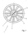
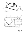
- a heat exchanger 1 of which only a cross section in the FIGS. 1 and 3 is shown, but may be formed in principle, as in Fig. 2 is shown with an enlarged, shown another cross-section provided.
- This heat exchanger 1 serves the heat exchange of a first medium and a second medium.
- the first medium flows through the inner region 2 of an inner tube 3 and the second medium through the outer region 4 which is formed between an outer tube 5 and the inner tube 3.
- the inner tube 3 and the outer tube 5 together with them in the radial direction in the longitudinal direction continuously extending ribs 6 are integrally extruded as a coaxial tube 7 made of an aluminum alloy.
- the outer diameter of the coaxial tube 7 is present 16 mm, the wall thickness of the outer tube 5 0.8 mm, the wall thickness of the inner tube 3 0.6 mm, the rib width 0.7 mm and the inner diameter 7 mm.
- 7 connecting components 8 are at both ends of the coaxial tube (see Fig. 2 ), via which the media, which in the present case flow in countercurrent operation through the inner region 2 or the outer region 4, are supplied or discharged separately from one another.
- coaxially extruded coaxial tube 7 On coaxially extruded coaxial tube 7 is located on the outer tube 5 (high pressure side) a higher pressure p a than on the inner tube 3 (low pressure side) to which the pressure p i is applied.
- the operating pressure on the low pressure side is according to the present embodiment about 130 bar, the corresponding bursting pressure 264 bar, and the operating pressure on the high pressure side is about 160 bar, the corresponding bursting pressure 352 bar.
- the mentioned pressure values refer in particular to the use of CO 2 (R744) as refrigerant.
- an improved, defined flow of the high-pressure refrigerant can be realized via the corresponding connecting piece 8, in particular, as in the present case Fig. 3 shown, a deflection-free flow of the high-pressure refrigerant provided in the direction of the longitudinal axis of the inner tube, whereby the pressure loss can be reduced and thereby the cooling capacity can be improved.
- the flow of the low-pressure refrigerant takes place in the radial direction with respect to the longitudinal axis of the coaxial tube. 1
- a turbulence generator 11 in the form of a helix (round tube helix) is provided which can be bent in the coaxial tube and bent with the same.
- the pitch of the helix in this case corresponds to a multiple of the inner diameter of the inner tube 3 and is constant over the entire Koaxialrohronne.
- the helix deflects the refrigerant flowing in the inner tube, so that no laminar flow is formed in the wall region, resulting in improved mixing and improved heat exchange.
- the pitch of the helix changes over the length of the coaxial tube and / or changes the direction of rotation of the helix, whereby multiple changes can be made.
- Fig. 4 shows a second embodiment which - unless mentioned below - corresponds to the first embodiment, but has no helix as a turbulence generator 11.
- the second embodiment are rather uniform over the inner circumference of the inner tube 3 distributed as a turbulence generator 11 eight inner ribs 21 provided in the radial direction inwardly projecting.
- the inner ribs have a rib thickness which is 0.1 mm less than the wall thickness of the outer tube 5.
- the length of the inner ribs 21 is presently 1 mm, so that they leave a circle of 5 mm diameter in the middle of the inner tube 3 free.
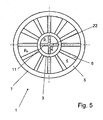
- Fig. 5 illustrated embodiment which, unless mentioned below - corresponds to the first embodiment, but has no coil as a turbulence generator 11, looks as a turbulence generator 11, two perpendicular crossing webs 22 in the inner tube 3, which quadrant the inner region 2.
- the web thickness is 0.1 mm less than the wall thickness of the outer tube 5.
- a coaxial tube 7 with a helix as a turbulence generator 11 which has different dimensions than the coaxial tube 7 of the first embodiment.
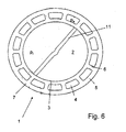
- a heat exchanger 1 of which only one cross section in Fig. 6 is shown, but may be formed in principle, as in Fig. 2 is shown with an enlarged, shown another cross-section provided.
- This heat exchange 1 serves heat exchange of a first medium and a second medium.
- the first medium flows through the inner region 2 of an inner tube 3 and the second medium through the outer region 4 which is formed between an outer tube 5 and the inner tube 3.
- the inner tube 3 and the outer tube 5 together with them in the radial direction in the longitudinal direction continuously extending ribs 6 are integrally extruded as a coaxial tube 7 made of an aluminum alloy.
- the outer diameter of the coaxial tube 7 is present 16 mm, the wall thickness of the outer tube 5 0.8 mm, the wall thickness of the inner tube 3 0.6 mm, the rib width 0.7 mm and the inner diameter 11 mm.
- the free cross-sectional area of the inner tube 3 is about 95 mm 2
- the sum of the free cross-sectional areas of the outer channels is about 35 mm 2 , that is about 60% smaller than that of the inner tube. 3
- a turbulence generator 11 in the form of a helix (round tube helix) is provided, which can be arranged in the coaxial tube bend with the same.
- the pitch of the helix in this case corresponds approximately to twice the inner diameter of the inner tube 3, ie about 22 mm, and is constant over the entire Koaxialrohronne.
- the helix deflects the refrigerant flowing in the inner tube, so that no laminar flow is formed in the wall region, resulting in improved mixing and improved heat exchange.
- 7 connecting components 8 are at both ends of the coaxial tube (see Fig. 2 ), via which the media, which in the present case flow in countercurrent operation through the inner region 2 or the outer region 4, are supplied or discharged separately from one another.
- a higher pressure is applied to the outer tube 5 (high pressure side) than to the inner tube 3 (low pressure side).
- the operating pressure on the low pressure side is according to the present embodiment about 130 bar, the corresponding bursting pressure 264 bar, and the operating pressure on the high pressure side is about 160 bar, the corresponding bursting pressure 352 bar.
- the mentioned pressure values refer in particular to the use of CO 2 (R744) as refrigerant.
- an improved flow of the low-pressure chaff agent can be realized via the corresponding connection piece 8, in particular, as in the present case Fig. 3 shown, a deflection-free flow of the low-pressure refrigerant provided in the direction of the longitudinal axis of the inner tube, whereby the pressure loss is reduced and thereby the cooling capacity can be improved.
- the Flow of the high-pressure refrigerant takes place in the radial direction with respect to the longitudinal axis of the coaxial tube. 1
- Fig. 7 shows a fifth embodiment of a coaxial tube, wherein in the inner tube 3 as turbulence generator 11 both four evenly distributed over the circumference inner ribs 21 are provided with a length of about half the radius and two perpendicular to each other and at a gap to the inner ribs 21 webs 22 which the Divide the interior into four separate areas. Otherwise, the coaxial tube 7 corresponds to that of the fourth embodiment, however, a corresponding embodiment of the turbulence generator 11 is also possible to the previously described form. These internals in the inner tube 3 increase the heat transfer area and therefore improve the heat exchange.
- the coaxial tube is extruded rotated, i. the ribs, inner ribs and webs run helically, in this case with a constant pitch.
- the coaxial tube is in turn rotated extruded, but changed with changing rotational speed, so that the pitch of the ribs, inner ribs and webs changed over the length of the coaxial tube.
- two tendons are provided opposite one another in the inner tube of the coaxial tube instead of the webs extending in the radial direction.
- a not shown in the drawing sixth embodiment provides a tube-in-tube arrangement as a coaxial tube, wherein the outer tube ribs and the inner tube as a turbulence generator inner ribs and webs, and the outer tube is soldered at the end of the ribs with the inner tube, thereby an embodiment according to the second embodiment results.
- a first variant of the sixth embodiment provides that the two tubes are extruded rotated in different directions, i. that the flow paths of the refrigerant flowing in the interior are rotated on the one hand in countercurrent operation and on the other hand in different directions, whereby the heat exchange is improved.
- the rotations of the two tubes have mutually over the length changing slopes, so that, for example, in the inflow a smaller pitch and in the outflow a greater pitch can be provided.
Landscapes
- Engineering & Computer Science (AREA)
- Physics & Mathematics (AREA)
- Thermal Sciences (AREA)
- Mechanical Engineering (AREA)
- General Engineering & Computer Science (AREA)
- Geometry (AREA)
- Heat-Exchange Devices With Radiators And Conduit Assemblies (AREA)
Claims (27)
- Tube coaxial pour la conduite séparée d'au moins deux milieux, où il est prévu, concernant le tube coaxial (7), au moins un et, dans une surface de section transversale, de préférence au maximum seize générateur(s) de turbulences (11) qui est ou sont disposé(s) dans la zone intérieure (2) du tube intérieur (3),
caractérisé en ce que le côté basse pression, dans le sens radial, est disposé en étant plus près de l'axe longitudinal médian que le côté haute pression, et la section d'écoulement libre du côté haute pression est, au total, inférieure à la section d'écoulement libre du côté basse pression, et où le tube intérieur et le tube extérieur sont extrudés à partir d'un alliage d'aluminium, comme un tube coaxial formant une seule et même pièce avec les ailettes s'étendant de façon continue suivant la direction longitudinale, dans le sens radial, entre le tube intérieur et le tube extérieur. - Tube coaxial selon la revendication 1, caractérisé en ce qu'il est prévu, dans une surface de section transversale, au maximum douze générateurs de turbulences (11).
- Tube coaxial selon la revendication 1 ou 2, caractérisé en ce que le générateur de turbulences (11) est formé par une hélice s'étendant dans la direction longitudinale du tube coaxial (1).
- Tube coaxial selon l'une quelconque des revendications précédentes, caractérisé en ce qu'il est prévu, comme générateur de turbulences (11), au moins une, en particulier au moins quatre et au maximum douze ailettes intérieures (21) placées dans le tube intérieur (3).
- Tube coaxial selon la revendication 4, caractérisé en ce que les ailettes intérieures (21) présentent une épaisseur d'ailette comprise entre 0,1 mm et 0,2 mm.
- Tube coaxial selon la revendication 4 ou 5, caractérisé en ce que les ailettes intérieures (21) présentent une hauteur d'ailette comprise entre 0,5 mm et 1,5 mm, dans le cas d'un diamètre intérieur du tube intérieur (3) compris entre 4 mm et 8 mm.
- Tube coaxial selon l'une quelconque des revendications 4 à 6, caractérisé en ce que les ailettes intérieures (21) sont configurées en s'étendant dans le sens radial.
- Tube coaxial selon l'une quelconque des revendications 4 à 7, caractérisé en ce que les ailettes intérieures (21) sont disposées en étant réparties, à intervalles équidistants, sur la circonférence intérieure du tube intérieur (3).
- Tube coaxial selon l'une quelconque des revendications précédentes, caractérisé en ce qu'il est prévu, comme générateur de turbulences (11), au moins une, en particulier deux ou trois barrettes (22) placées dans le tube intérieur (3).
- Tube coaxial selon la revendication 9, caractérisé en ce que la barrette (22) au moins au nombre de un est configurée en s'étendant dans le sens radial.
- Tube coaxial selon la revendication 9 ou 10, caractérisé en ce que la barrette (22) au moins au nombre de un présente une épaisseur de barrette comprise entre 0,2 mm et 0,6 mm.
- Tube coaxial selon l'une quelconque des revendications précédentes, caractérisé en ce qu'au moins l'un des générateurs de turbulences (11) et / ou au moins l'une des ailettes (6) placée entre le tube intérieur et le tube extérieur (3 et 5) sont disposés de façon oblique par rapport à l'axe longitudinal du tube.
- Tube coaxial selon la revendication 12, caractérisé en ce qu'au moins l'un des générateurs de turbulences (11) et / ou au moins l'une des ailettes (6) placée entre le tube intérieur et le tube extérieur (3 et 5) sont configurés de façon oblique par rapport à l'axe longitudinal du tube, en ayant un pas tel, qu'il se produit une rotation de 360° sur une longueur de tube comprise entre 15 mm et 40 mm, en particulier entre 20 mm et 30 mm.
- Tube coaxial selon l'une quelconque des revendications précédentes, caractérisé en ce que la longueur d'au moins l'un des générateurs de turbulences (11) et / ou d'au moins l'une des ailettes intérieures (21) et / ou d'au moins l'une des barrettes (22) et / ou d'au moins l'une des ailettes (6) placée entre le tube intérieur et le tube extérieur (3 et 5) correspond de 0,3 fois à 0,5 fois, de préférence à 0,4 fois la longueur du tube.
- Tube coaxial selon l'une quelconque des revendications précédentes, caractérisé en ce que la section d'écoulement libre du côté haute pression est au total, au maximum, à moitié aussi importante et, au minimum, un quart aussi importante, en particulier un tiers +/- 10 % aussi importante que la section d'écoulement libre du côté basse pression.
- Tube coaxial selon l'une quelconque des revendications précédentes, caractérisé en ce que le diamètre extérieur du tube extérieur est de 10 mm à 20 mm, en particulier de 12 mm à 18 mm.
- Tube coaxial selon l'une quelconque des revendications précédentes, caractérisé en ce que le diamètre intérieur du tube intérieur est de 3 mm à 10 mm, en particulier de 4 mm à 8 mm.
- Tube coaxial selon l'une quelconque des revendications précédentes, caractérisé en ce que la largeur d'ailettes (6) ou de barrettes, entre le tube intérieur et le tube extérieur (3 et 5), est de 0,3 mm à 1,1 mm, en particulier de 0,5 mm à 1,0 mm.
- Tube coaxial selon l'une quelconque des revendications précédentes, caractérisé en ce que les ouvertures d'arrivée des deux milieux sont disposées sur des côtés différents du tube coaxial.
- Tube coaxial selon l'une quelconque des revendications précédentes, caractérisé en ce que le tube extérieur est subdivisé en au moins six, en particulier en au moins huit, douze conduits partiels et, au maximum, en vingt, de préférence au maximum en seize conduits partiels.
- Tube coaxial selon l'une quelconque des revendications précédentes, caractérisé en ce que l'épaisseur de paroi de la paroi extérieure est plus importante ou de même importance que l'épaisseur de paroi de la paroi comprise entre le tube extérieur et le tube intérieur.
- Tube coaxial selon l'une quelconque des revendications précédentes, caractérisé en ce que l'épaisseur des ailettes ou barrettes, qui subdivise les différents conduits partiels du tube extérieur, est moins importante
ou de même importance que l'épaisseur de paroi de la paroi du tube extérieur. - Echangeur de chaleur du type à tubes coaxiaux, caractérisé par au moins un tube coaxial selon l'une quelconque des revendications 1 à 22.
- Echangeur de chaleur selon la revendication 23, caractérisé en ce qu'il est prévu au moins une pièce de raccordement (8) servant à introduire au moins un milieu, laquelle pièce de raccordement permet d'introduire le milieu suivant une direction coaxiale par rapport au tube coaxial (1).
- Système de climatisation, en particulier pour un véhicule automobile, caractérisé par au moins un tube coaxial selon l'une quelconque des revendications 1 à 22.
- Utilisation d'un tube coaxial selon l'une quelconque des revendications 1 à 22, d'un échangeur de chaleur selon la revendication 23 ou 24, ou bien d'un système de climatisation selon la revendication 25, où au moins l'un des milieux est un fluide frigorigène.
- Utilisation d'un tube coaxial selon l'une quelconque des revendications 1 à 22 ou 26, ou bien d'un échangeur de chaleur selon la revendication 23 ou 24 dans un circuit de fluide frigorigène.
Applications Claiming Priority (1)
| Application Number | Priority Date | Filing Date | Title |
|---|---|---|---|
| DE200510056650 DE102005056650A1 (de) | 2005-11-25 | 2005-11-25 | Koaxialrohr oder Rohr-in-Rohr-Anordnung, insbesondere für einen Wärmetauscher |
Publications (2)
| Publication Number | Publication Date |
|---|---|
| EP1790933A1 EP1790933A1 (fr) | 2007-05-30 |
| EP1790933B1 true EP1790933B1 (fr) | 2011-01-19 |
Family
ID=37887091
Family Applications (1)
| Application Number | Title | Priority Date | Filing Date |
|---|---|---|---|
| EP20060022999 Not-in-force EP1790933B1 (fr) | 2005-11-25 | 2006-11-06 | Tubes Coaxiales, en particulier pour un échangeur de chaleur |
Country Status (2)
| Country | Link |
|---|---|
| EP (1) | EP1790933B1 (fr) |
| DE (2) | DE102005056650A1 (fr) |
Cited By (2)
| Publication number | Priority date | Publication date | Assignee | Title |
|---|---|---|---|---|
| WO2016081481A1 (fr) * | 2014-11-17 | 2016-05-26 | Appollo Wind Technologies Llc | Dispositif turbocompresseur-détendeur-condenseur-évaporateur isothermique |
| WO2016081483A1 (fr) * | 2014-11-17 | 2016-05-26 | Appollo Wind Technologies Llc Greentown Labs | Turbocompresseur-condenseur-détendeur |
Families Citing this family (10)
| Publication number | Priority date | Publication date | Assignee | Title |
|---|---|---|---|---|
| ES2335953B1 (es) * | 2007-08-13 | 2010-10-25 | Valeo Termico, S.A. | Intercambiador de calor para gases, y su correspondiente procedimiento de fabricacion. |
| DE102011012577A1 (de) * | 2011-02-26 | 2012-08-30 | Volkswagen Ag | Wärmeaustauschvorrichtung |
| RU2502930C2 (ru) * | 2012-03-26 | 2013-12-27 | Открытое акционерное общество "Информационные спутниковые системы" имени академика М.Ф. Решетнева" | Струйный теплообменник типа труба в трубе |
| WO2014026176A1 (fr) * | 2012-08-10 | 2014-02-13 | Contitech Kuehner Gmbh & Cie Kg | Amélioration d'écoulement d'aspiration pour échangeur de chaleur interne |
| CN108779962B (zh) * | 2016-03-14 | 2020-04-07 | 康奈可关精株式会社 | 双层管 |
| DE102017222349A1 (de) * | 2017-12-11 | 2019-06-13 | Robert Bosch Gmbh | Absorbervorrichtung |
| CN110873542A (zh) * | 2018-08-29 | 2020-03-10 | 重庆蔓极科节能环保科技有限公司 | 三维肋片换热管 |
| DE102019112213A1 (de) * | 2019-05-10 | 2020-11-12 | Norma Germany Gmbh | Fluidleitung für ein Kühlwassersystem von elektrischen Fahrzeugen, Elektrisches Fahrzeug und Verwendung einer Fluidleitung |
| DE102021209341A1 (de) | 2021-08-25 | 2023-03-02 | Mahle International Gmbh | Wärmeübertrager |
| CN115355748A (zh) * | 2022-08-23 | 2022-11-18 | 珠海格力电器股份有限公司 | 换热管、热交换器及燃气热水器 |
Family Cites Families (18)
| Publication number | Priority date | Publication date | Assignee | Title |
|---|---|---|---|---|
| NL227564A (fr) * | ||||
| DD57940A (fr) * | ||||
| CH628134A5 (de) * | 1978-03-28 | 1982-02-15 | Ygnis Sa | Rauchgasdurchstroemter waermetauscher. |
| GB2078927B (en) * | 1980-06-20 | 1983-11-30 | Grumman Energy Systems Inc | Heat exchange system |
| DE3209207A1 (de) * | 1982-03-13 | 1983-09-15 | Stiebel Eltron Gmbh & Co Kg, 3450 Holzminden | Absorber fuer eine absorptionswaermepumpenanlage |
| GB2178518B (en) * | 1985-05-21 | 1988-12-14 | Specialist Heat Exchangers Ltd | Heat exchangers |
| US5497824A (en) * | 1990-01-18 | 1996-03-12 | Rouf; Mohammad A. | Method of improved heat transfer |
| JPH05164482A (ja) * | 1991-12-12 | 1993-06-29 | Kobe Steel Ltd | 液化天然ガスの気化装置 |
| JPH063075A (ja) * | 1992-06-18 | 1994-01-11 | Rinnai Corp | 液液熱交換器 |
| JP3131668B2 (ja) * | 1992-12-01 | 2001-02-05 | 昭和アルミニウム株式会社 | オイルクーラ |
| JPH10339588A (ja) * | 1997-06-06 | 1998-12-22 | Denso Corp | 熱交換器とその製造方法 |
| JP2000111277A (ja) * | 1998-10-09 | 2000-04-18 | Toyota Motor Corp | 2重配管式熱交換器 |
| JP2000161873A (ja) * | 1998-11-26 | 2000-06-16 | Toyota Motor Corp | 熱交換器 |
| DE19944951B4 (de) * | 1999-09-20 | 2010-06-10 | Behr Gmbh & Co. Kg | Klimaanlage mit innerem Wärmeübertrager |
| DE20011545U1 (de) * | 2000-07-01 | 2000-10-12 | Höcker, Hans-Peter, Dipl.-Ing. (FH), 91091 Großenseebach | Vorrichtung zum Austausch von Wärme |
| DE10053000A1 (de) * | 2000-10-25 | 2002-05-08 | Eaton Fluid Power Gmbh | Klimaanlage mit innerem Wärmetauscher und Wärmetauscherrohr für einen solchen |
| DE10349140A1 (de) * | 2003-10-17 | 2005-05-12 | Behr Gmbh & Co Kg | Wärmeübertrager, insbesondere für Kraftfahrzeuge |
| DE10349504A1 (de) * | 2003-10-23 | 2005-05-25 | Bayer Technology Services Gmbh | Verfahren zur Herstellung von Isocyanaten in der Gasphase |
-
2005
- 2005-11-25 DE DE200510056650 patent/DE102005056650A1/de not_active Withdrawn
-
2006
- 2006-11-06 EP EP20060022999 patent/EP1790933B1/fr not_active Not-in-force
- 2006-11-06 DE DE200650008755 patent/DE502006008755D1/de active Active
Cited By (3)
| Publication number | Priority date | Publication date | Assignee | Title |
|---|---|---|---|---|
| WO2016081481A1 (fr) * | 2014-11-17 | 2016-05-26 | Appollo Wind Technologies Llc | Dispositif turbocompresseur-détendeur-condenseur-évaporateur isothermique |
| WO2016081483A1 (fr) * | 2014-11-17 | 2016-05-26 | Appollo Wind Technologies Llc Greentown Labs | Turbocompresseur-condenseur-détendeur |
| US9772122B2 (en) | 2014-11-17 | 2017-09-26 | Appollo Wind Technologies Llc | Turbo-compressor-condenser-expander |
Also Published As
| Publication number | Publication date |
|---|---|
| DE102005056650A1 (de) | 2007-05-31 |
| EP1790933A1 (fr) | 2007-05-30 |
| DE502006008755D1 (de) | 2011-03-03 |
Similar Documents
| Publication | Publication Date | Title |
|---|---|---|
| EP1654508B2 (fr) | Echangeur de chaleur et procede de fabrication dudit echangeur | |
| EP1837499B1 (fr) | Dispositif destiné au refroidissement d'un flux de gaz d'échappement | |
| EP1790933B1 (fr) | Tubes Coaxiales, en particulier pour un échangeur de chaleur | |
| DE2209325A1 (de) | Waermeaustauschrohr mit innenrippen und verfahren zu seiner herstellung | |
| DE102005052683B4 (de) | Mehrkanalflachrohr für Wärmeübertrager | |
| EP0714008A2 (fr) | Echangeur de chaleur avec boîte à eau | |
| DE102015104180B4 (de) | Vorrichtung für einen Wärmeübertrager zum Sammeln und Verteilen eines Wärmeträgerfluids | |
| EP1790931A2 (fr) | Ensemble coaxial ou tube dans tube, en particulier pour échangeur de chaleur | |
| DE10100241A1 (de) | Wärmetauscherrohr für flüssige oder gasförmige Medien | |
| EP3491323B1 (fr) | Échangeur de chaleur présentant une structure à micro-canal ou une structure à tube à ailettes | |
| EP3056847A1 (fr) | Dispositif et procede destines a la thermoregulation d'un corps | |
| EP2447626B1 (fr) | Echangeur thermique, notamment pour l'application dans des meubles réfrigérants | |
| EP3009780B2 (fr) | Fluide caloporteur | |
| DE102015102311A1 (de) | Rohrbündelwärmeübertrager | |
| DE10000288C1 (de) | Spiralwärmeaustauscher | |
| DE102008020230A1 (de) | Wärmetauscher sowie Wärmetauscherrohr | |
| EP2937658B1 (fr) | Fluide caloporteur interne | |
| EP1788320B1 (fr) | Echangeur de chaleur | |
| EP4237782B1 (fr) | Tube métallique d'échangeur de chaleur | |
| EP4237781B1 (fr) | Tube métallique d'échangeur de chaleur | |
| EP1798507A2 (fr) | Echangeur de chaleur, en particulier évaporateur | |
| EP1331464B1 (fr) | Echangeur de chaleur | |
| EP3569953B1 (fr) | Dispositif de circuit réfrigérant et procédé de fonctionnement d'un dispositif de circuit réfrigérant doté d'un évaporateur hybride | |
| DE102009057232A1 (de) | Rohrförmiger Wärmetauscher für Kraftfahrzeug-Klimaanlage | |
| EP3001130A1 (fr) | Corps chauffant, circuit réfrigerant, appareil de climatisation pour une installation de climatisation de véhicule automobile, et installation de climatisation pour un véhicule automobile |
Legal Events
| Date | Code | Title | Description |
|---|---|---|---|
| PUAI | Public reference made under article 153(3) epc to a published international application that has entered the european phase |
Free format text: ORIGINAL CODE: 0009012 |
|
| AK | Designated contracting states |
Kind code of ref document: A1 Designated state(s): AT BE BG CH CY CZ DE DK EE ES FI FR GB GR HU IE IS IT LI LT LU LV MC NL PL PT RO SE SI SK TR |
|
| AX | Request for extension of the european patent |
Extension state: AL BA HR MK YU |
|
| 17P | Request for examination filed |
Effective date: 20071130 |
|
| 17Q | First examination report despatched |
Effective date: 20080110 |
|
| AKX | Designation fees paid |
Designated state(s): DE FR GB |
|
| GRAP | Despatch of communication of intention to grant a patent |
Free format text: ORIGINAL CODE: EPIDOSNIGR1 |
|
| GRAS | Grant fee paid |
Free format text: ORIGINAL CODE: EPIDOSNIGR3 |
|
| GRAA | (expected) grant |
Free format text: ORIGINAL CODE: 0009210 |
|
| AK | Designated contracting states |
Kind code of ref document: B1 Designated state(s): DE FR GB |
|
| REG | Reference to a national code |
Ref country code: GB Ref legal event code: FG4D Free format text: NOT ENGLISH |
|
| REF | Corresponds to: |
Ref document number: 502006008755 Country of ref document: DE Date of ref document: 20110303 Kind code of ref document: P |
|
| REG | Reference to a national code |
Ref country code: DE Ref legal event code: R096 Ref document number: 502006008755 Country of ref document: DE Effective date: 20110303 |
|
| PLBE | No opposition filed within time limit |
Free format text: ORIGINAL CODE: 0009261 |
|
| STAA | Information on the status of an ep patent application or granted ep patent |
Free format text: STATUS: NO OPPOSITION FILED WITHIN TIME LIMIT |
|
| 26N | No opposition filed |
Effective date: 20111020 |
|
| REG | Reference to a national code |
Ref country code: DE Ref legal event code: R097 Ref document number: 502006008755 Country of ref document: DE Effective date: 20111020 |
|
| GBPC | Gb: european patent ceased through non-payment of renewal fee |
Effective date: 20111106 |
|
| REG | Reference to a national code |
Ref country code: FR Ref legal event code: ST Effective date: 20120731 |
|
| PG25 | Lapsed in a contracting state [announced via postgrant information from national office to epo] |
Ref country code: GB Free format text: LAPSE BECAUSE OF NON-PAYMENT OF DUE FEES Effective date: 20111106 |
|
| PG25 | Lapsed in a contracting state [announced via postgrant information from national office to epo] |
Ref country code: FR Free format text: LAPSE BECAUSE OF NON-PAYMENT OF DUE FEES Effective date: 20111130 |
|
| REG | Reference to a national code |
Ref country code: DE Ref legal event code: R082 Ref document number: 502006008755 Country of ref document: DE Representative=s name: GRAUEL, ANDREAS, DIPL.-PHYS. DR. RER. NAT., DE |
|
| REG | Reference to a national code |
Ref country code: DE Ref legal event code: R082 Ref document number: 502006008755 Country of ref document: DE Representative=s name: GRAUEL, ANDREAS, DIPL.-PHYS. DR. RER. NAT., DE Effective date: 20150304 Ref country code: DE Ref legal event code: R081 Ref document number: 502006008755 Country of ref document: DE Owner name: MAHLE INTERNATIONAL GMBH, DE Free format text: FORMER OWNER: BEHR GMBH & CO. KG, 70469 STUTTGART, DE Effective date: 20150304 |
|
| PGFP | Annual fee paid to national office [announced via postgrant information from national office to epo] |
Ref country code: DE Payment date: 20181203 Year of fee payment: 13 |
|
| REG | Reference to a national code |
Ref country code: DE Ref legal event code: R119 Ref document number: 502006008755 Country of ref document: DE |
|
| PG25 | Lapsed in a contracting state [announced via postgrant information from national office to epo] |
Ref country code: DE Free format text: LAPSE BECAUSE OF NON-PAYMENT OF DUE FEES Effective date: 20200603 |