EP4237781B1 - Tube métallique d'échangeur de chaleur - Google Patents
Tube métallique d'échangeur de chaleur Download PDFInfo
- Publication number
- EP4237781B1 EP4237781B1 EP21793853.9A EP21793853A EP4237781B1 EP 4237781 B1 EP4237781 B1 EP 4237781B1 EP 21793853 A EP21793853 A EP 21793853A EP 4237781 B1 EP4237781 B1 EP 4237781B1
- Authority
- EP
- European Patent Office
- Prior art keywords
- channel
- projections
- cavities
- rib
- heat exchange
- Prior art date
- Legal status (The legal status is an assumption and is not a legal conclusion. Google has not performed a legal analysis and makes no representation as to the accuracy of the status listed.)
- Active
Links
Images

Classifications
-
- F—MECHANICAL ENGINEERING; LIGHTING; HEATING; WEAPONS; BLASTING
- F28—HEAT EXCHANGE IN GENERAL
- F28F—DETAILS OF HEAT-EXCHANGE AND HEAT-TRANSFER APPARATUS, OF GENERAL APPLICATION
- F28F1/00—Tubular elements; Assemblies of tubular elements
- F28F1/10—Tubular elements and assemblies thereof with means for increasing heat-transfer area, e.g. with fins, with projections, with recesses
- F28F1/12—Tubular elements and assemblies thereof with means for increasing heat-transfer area, e.g. with fins, with projections, with recesses the means being only outside the tubular element
- F28F1/34—Tubular elements and assemblies thereof with means for increasing heat-transfer area, e.g. with fins, with projections, with recesses the means being only outside the tubular element and extending obliquely
- F28F1/36—Tubular elements and assemblies thereof with means for increasing heat-transfer area, e.g. with fins, with projections, with recesses the means being only outside the tubular element and extending obliquely the means being helically wound fins or wire spirals
-
- F—MECHANICAL ENGINEERING; LIGHTING; HEATING; WEAPONS; BLASTING
- F28—HEAT EXCHANGE IN GENERAL
- F28F—DETAILS OF HEAT-EXCHANGE AND HEAT-TRANSFER APPARATUS, OF GENERAL APPLICATION
- F28F1/00—Tubular elements; Assemblies of tubular elements
- F28F1/10—Tubular elements and assemblies thereof with means for increasing heat-transfer area, e.g. with fins, with projections, with recesses
- F28F1/42—Tubular elements and assemblies thereof with means for increasing heat-transfer area, e.g. with fins, with projections, with recesses the means being both outside and inside the tubular element
- F28F1/422—Tubular elements and assemblies thereof with means for increasing heat-transfer area, e.g. with fins, with projections, with recesses the means being both outside and inside the tubular element with outside means integral with the tubular element and inside means integral with the tubular element
-
- F—MECHANICAL ENGINEERING; LIGHTING; HEATING; WEAPONS; BLASTING
- F28—HEAT EXCHANGE IN GENERAL
- F28F—DETAILS OF HEAT-EXCHANGE AND HEAT-TRANSFER APPARATUS, OF GENERAL APPLICATION
- F28F13/00—Arrangements for modifying heat-transfer, e.g. increasing, decreasing
- F28F13/18—Arrangements for modifying heat-transfer, e.g. increasing, decreasing by applying coatings, e.g. radiation-absorbing, radiation-reflecting; by surface treatment, e.g. polishing
- F28F13/185—Heat-exchange surfaces provided with microstructures or with porous coatings
- F28F13/187—Heat-exchange surfaces provided with microstructures or with porous coatings especially adapted for evaporator surfaces or condenser surfaces, e.g. with nucleation sites
-
- F—MECHANICAL ENGINEERING; LIGHTING; HEATING; WEAPONS; BLASTING
- F28—HEAT EXCHANGE IN GENERAL
- F28F—DETAILS OF HEAT-EXCHANGE AND HEAT-TRANSFER APPARATUS, OF GENERAL APPLICATION
- F28F2215/00—Fins
-
- F—MECHANICAL ENGINEERING; LIGHTING; HEATING; WEAPONS; BLASTING
- F28—HEAT EXCHANGE IN GENERAL
- F28F—DETAILS OF HEAT-EXCHANGE AND HEAT-TRANSFER APPARATUS, OF GENERAL APPLICATION
- F28F2215/00—Fins
- F28F2215/10—Secondary fins, e.g. projections or recesses on main fins
Definitions
- the invention relates to a metallic heat exchanger tube according to the preamble of claim 1.
- DE 10 2014 002829 A1 eg discloses such a heat exchanger tube.
- Shell-and-tube heat exchangers are often used in which liquids of pure substances or mixtures evaporate on the outside of the tube and cool a brine or water on the inside of the tube.
- the size of the evaporator can be reduced significantly. This reduces the manufacturing costs of such devices.
- the required amount of coolant is reduced, which can represent a significant proportion of the total system costs in the case of the chlorine-free safety coolants that are now predominantly used.
- the high-performance pipes commonly used today are already four times more efficient than smooth pipes of the same diameter.
- the most powerful commercially available finned tubes for flooded evaporators have a fin structure on the outside of the tube with a fin density of 55 to 60 fins per inch ( US 5,669,441 A ; US 5,697,430 A ; DE 197 57 526 C1 ). This corresponds to a fin pitch of approximately 0.45 to 0.40 mm. It is also known that evaporation structures with increased performance can be created with the same fin pitch on the outside of the tube by adding additional structural elements in the area of the groove base between the ribs.
- EP 1 223 400 B1 It is proposed to create undercut secondary grooves at the groove base between the ribs, which extend continuously along the primary groove.
- the cross-section of these secondary grooves can remain constant or be varied at regular intervals.
- DE 10 2008 013 929 B3 Structures are known at the groove base, which are designed as local cavities, whereby the process of bubble boiling is intensified to increase the heat transfer during evaporation.
- the location of the cavities near the primary groove base is favorable for the evaporation process, since the excess temperature is greatest at the groove base and therefore the highest driving temperature difference for bubble formation is available there.
- EP 3 111 153 B1 Another approach with higher structures starting from the groove bottom is in EP 3 111 153 B1 revealed.
- the structures are projections in the channel that cause segmentation. By segmenting between two ribs, the channel is repeatedly interrupted in the circumferential direction, thus at least reducing or completely preventing the migration of the bubbles and the heat exchange fluid that are created in the channel. A Exchange of liquid and vapor along the channel is increasingly less or no longer supported by the respective additional structure.
- the invention is based on the object of developing a performance-enhanced heat exchanger tube for the evaporation of liquids on the outside of the tube.
- the invention includes a metallic heat exchanger tube with integral fins formed on the outside of the tube with a fin base, fin flanks and fin tip, wherein the fin base protrudes radially from the tube wall and a channel with a channel base is formed between the fins, in which additional structures are arranged at a distance from one another.
- the additional structures divide the channel between the fins into segments.
- the additional structures locally reduce the cross-sectional area through which flow can pass in the channel between two fins and thereby at least limit a fluid flow in the channel during operation.
- First additional structures are projections extending radially outwards from the channel base, which are each limited in the radial direction by an end surface located between the channel base and the fin tip, whereby a radial extension of the projections is defined.
- cavities are arranged radially outwards as second additional structures, which are formed from material of the fin flanks and the radially outward end surface of the projections.
- the cavities are arranged in the radial direction between a closing surface and the rib tip, so that the cavities are arranged around the radial extension of the projections above the channel base of the channel are formed laterally on the rib flank.
- the cavities are open in the axial direction.
- These metallic heat exchanger tubes are used in particular for the evaporation of liquids from pure substances or mixtures on the outside of the tube.
- Integrally rolled finned pipes are finned pipes in which the fins are formed from the wall material of a smooth pipe.
- Typical integral fins formed on the outside of the pipe are, for example, spirally circumferential and have a fin base, fin flanks and fin tip, with the fin base protruding essentially radially from the pipe wall. The number of fins is determined by counting successive bulges in the axial direction of a pipe.
- the structures according to the invention are manufactured using a sharp-edged rolling disk, which preforms material from the fin flank to form the projection, and a toothed rolling disk that follows in the process and forms both the wall material at the channel base and the preformed material on the fin flank to form the cavity.
- the structures according to the invention can be produced solely by a toothed rolling disk, which forms both wall material at the channel base and material from the rib flank to form the cavity.
- the invention is based on the idea that in order to increase the heat transfer during evaporation, the space between the fins is segmented by additional structures. This creates local overheating in the spaces and intensifies the process of bubble boiling. The formation of bubbles then takes place primarily within the segments and begins at the nucleation points. Small gas or vapor bubbles initially form at these nucleation points. When the growing bubble has reached a certain size, it detaches from the surface. As the bubble detaches, the remaining cavity in the segment is flooded with liquid again and the cycle begins again.
- the surface can be designed in such a way that when the bubble detaches, a small bubble remains behind, which then serves as the nucleation point for a new cycle of bubble formation.
- bubble nucleation sites in the area of the first additional structures in the form of radially outward-facing projections.
- the bubble nucleation sites sit as cavities on the projections lying radially outward.
- bubble nuclei are preferably formed, which contribute to the formation of bubbles in the segment.
- the projections can extend between the respective rib base of adjacent ribs in the axial direction over the entire channel base or only over part of the channel base. They represent a barrier running between two ribs starting from the channel base, which extends radially outward and at least partially closes the channel in the circumferential direction.
- the projections, which are spaced apart from one another and follow one another in the channel, and the cavities lying radially outward as additional structures can each vary in height and shape.
- the cavity placed on the basic channel structure is made from material from the rib flank and essentially forms a flowing transition in the radial direction to the two side surfaces of the projection below.
- the cavity is designed like a cave from side surfaces and a cover surface, which represents the end in the direction of the rib tip, as well as from the radially outer end surface of the projections and from the rear-bounding surface portion of the rib flank.
- these side surfaces and cover surface form the boundary surfaces, which extend approximately in the direction of the longitudinal axis of the pipe and, for example, reach into this axial direction approximately to the middle of the channel.
- a radially outer end surface of the projections can extend across the entire width of the channel.
- the cavity has an opening for the bubble nuclei to exit in the axial direction. From there, a bubble nucleus can contribute to bubble formation in both adjacent segments in the circumferential direction. At the location of this bubble nucleus exit point, which is arranged on a projection, liquid fluid can also be exchanged between neighboring segments, as long as no bubble nucleus formed from gaseous fluid dominates there and virtually prevents passage. In other words: as long as no bubble nucleus fills the connection point between neighboring segments, liquid fluid can also pass from one segment into a neighboring segment.
- the projections with the attached cavities therefore represent a threshold for fluid passage.
- the side surfaces of a cavity can also be made longer than the cover surface in the axial direction towards the neighboring rib. This results in an opening of the cavity that is inclined to the longitudinal axis of the pipe, which allows bubble nuclei to more easily enter the neighboring segments for the bubbles to grow.
- the frontal contour line of the side and cover surface that forms an opening of the cavity can also be curved or irregular. In these preferred embodiments, a cavity also remains certain inclination essentially opens in the axial direction.
- this type of segmentation of the channel between two ribs means that it is repeatedly interrupted in the circumferential direction, thus at least reducing or completely preventing the migration of the bubbles that form in the channel.
- An exchange of liquid and vapor along the channel is increasingly less or no longer supported by the respective additional structure.
- the particular advantage of the invention is that the exchange of liquid and vapor is controlled locally and the flooding of the bubble nucleation point in the segment takes place locally.
- the evaporator tube structures can be optimized in a targeted manner depending on the application parameters through a targeted selection of the channel segmentation, thereby increasing the heat transfer. Since the temperature of the fin base is higher in the area of the groove base than at the fin tip, structural elements for intensifying the bubble formation in the groove base are particularly effective.
- the additional structures locally reduce the cross-sectional area through which the flow can pass in the channel between two fins.
- the evaporator tube structures can be further optimized to increase heat transfer depending on the application parameters.
- the projections and the cavities can locally reduce the cross-sectional area of the channel between two ribs by at least 30%.
- the segments are locally sufficiently delimited for fluid passage.
- the channel section located between two segments is thus The fluid side of the channel sections is sufficiently to largely separated.
- the projections and the cavities can locally reduce the flow-through cross-sectional area in the channel between two ribs by 40 to 70%.
- the channel section located between two segments forms a significant threshold on the fluid side compared to adjacent channel sections.
- the channel can be closed off radially to the outside except for individual local openings.
- the ribs can have a substantially T-shaped or ⁇ -shaped cross-section, whereby the channel between the ribs is closed off except for pores as local openings. The vapor bubbles created in the evaporation process can escape through these openings. The deformation of the rib tips takes place using methods that can be taken from the state of the art.
- the rib tips can also be folded over in the axial direction or even shaped to a certain extent towards the base of the channel.
- the channel can therefore also be tapered to the desired extent or completely closed using a combination of several complementary structural elements from below and the side and/or from above. In any case, in such a way that the channel between the ribs is divided into discrete segments.
- the local openings are designed in such a way that liquid medium can also pass through and flow into the channel section. In order for the evaporation process to be maintained at a local opening, the same amounts of liquid and vapor must therefore be transported through the opening in opposite directions. Liquids that wet the pipe material well are usually used. Due to the capillary effect, such a liquid can penetrate into the channels through any opening in the outer pipe surface, even against excess pressure.
- the ratio of the number of local openings to the number of segments can be 1:1 to 6:1. More preferably, this ratio can be 1:1 to 3:1.
- the channels between the ribs are essentially closed by material from the upper rib regions, with the resulting cavities in the channel segments being connected to the surrounding space by openings.
- These openings can also be designed as pores, which can be the same size or in two or more size classes. In a ratio in which several local openings are formed on one segment, pores with two size classes can be particularly suitable. According to a regular, repeating pattern, for example, every small opening is followed by a large opening along the channels. This structure creates a directed flow in the channels.
- Liquid is preferably drawn in through the small pores with the support of capillary pressure and wets the channel walls, creating thin films.
- the vapor collects in the center of the channel and escapes at the points with the lowest capillary pressure.
- the large pores must be dimensioned so that the steam can pass through quickly enough can escape without the channels drying out.
- the size and frequency of the steam pores in relation to the smaller liquid pores must then be coordinated.
- the projections can be formed as first additional structures at least from material of the channel base between two integrally surrounding ribs. This maintains a material-locking connection for good heat exchange from the pipe wall to the respective structural elements.
- a projection can also consist of material from the rib flank. Segmenting the channel from a uniform material of the channel base is particularly favorable for the evaporation process.
- the projections as the first additional structures can have a height of between 0.15 and 1 mm. This dimensioning of the additional structures is particularly well suited to the high-performance finned tubes and expresses the fact that the structural sizes of the external structures are preferably in the submillimeter to millimeter range.
- the projections can advantageously have asymmetrical shapes.
- the asymmetry of the structures appears in a cutting plane that runs perpendicular to the longitudinal axis of the pipe.
- Asymmetrical shapes can make an additional contribution to the evaporation process, particularly if a larger surface is formed.
- the asymmetry can be pronounced both in additional structures at the channel base and at the fin tip.
- the projections can have a trapezoidal cross-section in a cutting plane running perpendicular to the longitudinal axis of the tube.
- Trapezoidal cross-sections are technologically easy to control in connection with integrally rolled finned tube structures. Structural elements. Minor manufacturing-related asymmetries of the otherwise parallel base sides of a trapezoid can occur.
- two opposing cavities can be formed at the location of the projections in the direction of the pipe longitudinal axis.
- the openings for the bubble nuclei to emerge are therefore directly opposite each other in the axial direction of the two cavities. From there, a bubble nucleus can contribute to the formation of bubbles in both segments that are adjacent in the circumferential direction.
- the projections with the two cavities attached to them therefore represent the threshold for the fluid to pass through.
- Cavity openings that are inclined to the longitudinal axis of the pipe can prove to be particularly advantageous, as they allow bubble nuclei to more easily enter the neighboring segments for the bubbles to grow.
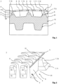
- Fig. 1 shows a schematic partial view of a cross section of a heat exchanger tube 1 according to the invention with segments 8 divided by additional structures 7.
- the integrally rolled heat exchanger tube 1 has helical ribs 2 on the outside of the tube, between which a primary groove is formed as a channel 6.
- the ribs 2 extend continuously without interruption along a helical line on the outside of the tube.
- the rib base 3 protrudes essentially radially from the tube wall 10.
- the rib height H is measured on the finished heat exchanger tube 1 from the lowest point of the channel base 61 to the rib tip 5 of the fully formed ribbed tube.
- a heat exchanger tube 1 is proposed in which an additional structure 7 in the form of radially outward-directed projections 71 is arranged in the region of the channel base 61, which are each delimited in the radial direction by an end surface 713 located between the channel base 61 and the fin tip 5.
- These projections 71 are referred to as the first additional structure and are formed from material of the tube wall 10 from the channel base 61.
- the projections 71 are arranged at preferably regular intervals in the channel base 61 and extend transversely to the channel course from a fin base 3 of a fin 2 at least partially in the direction or completely to the next fin base above it, not shown in the plane of the figure.
- cavities 72 are arranged radially outward as a second additional structure 7, which are formed from material of the fin flanks 4 and the radially outwardly arranged end surface 713 of the projections 71.
- the cavities are arranged in the radial direction between a closing surface 713 and the rib tip 5, so that the cavities 72 are formed around the radial extension of the projections 71 above the channel base 61 of the channel 6 laterally on the rib flank 4.
- the cavities 72 are arranged in the axial direction opened. In this way, the primary groove as channel 6 is at least partially tapered at regular intervals.
- the resulting segment 8 promotes bubble nucleation in connection with the cavities 72 in a special way. The exchange of liquid and vapor between the individual segments 8 is at least reduced.
- the rib tips 5 as the distal region of the ribs 2 are expediently deformed in such a way that they partially close the channel 6 in the radial direction with an axially folded rib tip 51.
- the connection between the channel 6 and the environment is designed in the form of pores 9 as local openings so that vapor bubbles can escape from the channel 6.
- the deformation of the rib tips 5 takes place using rolling methods that can be taken from the state of the art.
- the primary grooves 6 thus represent undercut grooves.
- a segment 8 in the form of a cavity is obtained, which is also characterized by the fact that it has a very high performance in the evaporation of liquids over a very wide range of operating conditions.
- the liquid evaporates within the segment 8, supported by cavities 72 as additional nucleation sites.
- the resulting vapor exits the channel 6 at the local openings 9, through which liquid fluid also flows. Easily wettable pipe surfaces can also be helpful for the fluid to flow.
- the solution according to the invention relates to structured tubes in which the heat transfer coefficient is increased on the outside of the tube.
- the heat transfer coefficient on the inside can also be intensified by a suitable internal structuring 11.
- the heat exchanger tubes 1 for shell-and-tube heat exchangers usually have at least one structured area as well as smooth end pieces and possibly smooth intermediate pieces. The smooth end pieces or intermediate pieces delimit the structured areas. So that the heat exchanger tube 1 can be installed easily in the shell-and-tube heat exchanger, the outer diameter of the structured areas must not be larger than the outer diameter of the smooth end pieces and intermediate pieces.
- Fig. 2 shows a schematic oblique view of part of the external structure of a heat exchanger tube 1 with folded fin tips 51.
- the fin tips 5 as the distal region of the fins 2 are deformed in such a way that they partially close the channel 6 in the radial direction with an axially folded fin tip 51.
- the connection between the channel 6 and the environment is designed as local openings 9 for the escape of vapor bubbles from the channel 6 and the flow of liquid fluid into the channel 6.
- the primary grooves 6 thus again represent undercut grooves.
- the axially folded fin tip 51 is formed from the fin 2 and thus extends in the axial direction across the channel 6.
- the transition area from the rib flank 4 to the folded rib tip 51 can be seen in the figure by a small plateau-like structure along the rib course.
- the additional structures 7 the flow-through cross-sectional area in the channel 6 between two ribs 2 is reduced locally particularly effectively in order to limit the fluid flow in the channel 6 during operation.
- Fig. 3 shows schematically a detailed view of a cavity 72 at the location of a projection 71.
- the cavity 72 which is placed radially on a preferably solid projection 71, is made of material of the rib flank 4 by a toothed rolling disk which forms both wall material at the channel base 61 and material at the rib flank 4.
- projections 71 and cavities 72 are thus formed from different areas of the pipe wall, a cavity 72 can essentially form a radially flowing transition to the two side surfaces 711 of the projection 71 below.
- the projection 71 extends only in a part of the channel base 61 and ends in the axial direction of the pipe with an end face 712.
- the cavity 72 is cave-like and consists of side surfaces 721 and a cover surface 722 as well as the radially outer end surface 713 of the projection 71 and the rear-bounding surface portion (in the Figure 3 by a side surface 721) of the rib flank.
- the side surfaces 721, cover surface 722 and end surface 713 of the projection 71 are the boundary surfaces of the cavity 72, which extend approximately in the direction of the longitudinal axis A of the pipe and are, for example, pronounced in this axial direction up to approximately the middle of the channel.
- the end surface 713 of the projection 71 can extend further in the direction of the longitudinal axis A of the pipe or even over the entire width of the channel between opposing ribs.
- the cavity 72 has an opening 723 for the exit of the bubble nuclei essentially in the axial direction of the pipe. From there, a bubble nucleus can contribute to the formation of bubbles in both segments 8 adjacent in the circumferential direction.
- the projections 71 with the attached cavities 72 therefore represent a threshold for the passage of fluid.
- the side surfaces 721 of the cavity 72 are longer than the cover surface 722 in the axial direction towards the adjacent rib. This results in an opening 723 of the cavity 72 that is inclined to the longitudinal axis A of the tube, which more easily releases bubble nuclei into the adjacent segments 8 for the bubbles to grow. Nevertheless, a cavity 72 is essentially open in the axial direction A even when the opening 723 is slightly inclined.
- Fig. 4 shows a schematic oblique view of a part of the external structure of a heat exchanger tube 1 with two opposing cavities 72 at the location of a projection 71 and with folded fin tips 51.
- the fin tips 5 as the distal region of the fins 2 are deformed in such a way that they partially close the channel 6 in the radial direction with an axially folded fin tip 51.
- the connection between the channel 6 and the environment is designed as local openings 9 for the escape of vapor bubbles from the channel 6 and the flow of liquid fluid into the channel 6.
- the projections 71 and cavities 72 as additional structures 7, the flow-through cross-sectional area in the channel 6 between two ribs 2 is reduced locally particularly effectively in order to thereby limit the fluid flow in the channel 6 during operation.
- the projections 71 extend over the entire channel width between adjacent ribs 2 in the direction of the longitudinal pipe axis A.
- Two opposing cavities 72 are formed radially outward at the location of the projections 71.
- the openings for the exit of the bubble nuclei are therefore directly opposite each other in the axial direction A in the two cavities 72.
- a bubble nucleus can contribute to the formation of bubbles in both segments adjacent in the circumferential direction.
- the projections 71 with the two attached cavities 72 therefore represent a threshold for the passage of fluid. Openings of the cavities 72 that are slightly inclined to the longitudinal pipe axis A can also prove to be particularly advantageous, as they release bubble nuclei more easily into the adjacent segments for the bubbles to grow.
Landscapes
- Engineering & Computer Science (AREA)
- Physics & Mathematics (AREA)
- Thermal Sciences (AREA)
- Mechanical Engineering (AREA)
- General Engineering & Computer Science (AREA)
- Geometry (AREA)
- Chemical & Material Sciences (AREA)
- Crystallography & Structural Chemistry (AREA)
- Heat-Exchange Devices With Radiators And Conduit Assemblies (AREA)
Claims (10)
- Tube d'échangeur de chaleur (1) métallique, avec des nervures (2) intégrales formées sur le côté extérieur de tube avec un pied de nervure (3), des flancs de nervure (4) et une pointe de nervure (5), dans lequel le pied de nervure (3) dépasse radialement depuis la paroi de tube (10) et entre les nervures (2) est conçu un canal (6) avec une base de canal (61) dans lequel sont agencées des structures additionnelles (7, 71, 72) espacées les unes des autres,- lesquelles subdivisent en segments (8) le canal (6) entre les nervures (2),- lesquelles réduisent localement la surface de section transversale pouvant être traversée dans le canal (6) entre deux nervures (2) et au moins délimitent ainsi pendant le fonctionnement un flux de fluide dans le canal (6), et- dans lequel des premières structures additionnelles (7, 71) sont des protubérances (71) partant de la base de canal (61) et orientées radialement vers l'extérieur qui sont respectivement délimitées dans la direction radiale par une surface de terminaison (713) se trouvant entre la base de canal (61) et la pointe de nervure (5), moyennant quoi est définie une extension radiale des protubérances (71),caractérisé en ce que- à l'emplacement des protubérances (71), en tant que deuxièmes structures additionnelles (7, 72) sont agencées des cavités (72) se situant radialement vers l'extérieur, qui sont conçues dans le matériau des flancs de nervure (4) et de la surface de terminaison (713), agencée radialement à l'extérieur, des protubérances (71),- les cavités (72) sont respectivement agencées dans la direction radiale entre une surface de terminaison (713) et la pointe de nervure (5), de sorte que les cavités (72) soient conçues de façon à se situer latéralement contre le flanc de nervure (4), autour de l'extension radiale des protubérances (71) et par-dessus la base de canal (61) du canal (6), et- les cavités (72) sont ouvertes dans la direction axiale.
- Tube d'échangeur de chaleur (1) selon la revendication 1, caractérisé en ce que les protubérances (71) et les cavités (72) réduisent localement d'au moins 30 % la surface de section transversale pouvant être traversée dans le canal (6) entre deux nervures (2).
- Tube d'échangeur de chaleur (1) selon la revendication 1 ou 2, caractérisé en ce que les protubérances (71) et les cavités (72) réduisent localement de 40 % à 70 % la surface de section transversale pouvant être traversée dans le canal (6) entre deux nervures (2).
- Tube d'échangeur de chaleur (1) selon l'une des revendications 1 à 3, caractérisé en ce que le canal (6) est terminé radialement vers l'extérieur à l'exception d'ouvertures (9) locales individuelles.
- Tube d'échangeur de chaleur (1) selon l'une des revendications 1 à 4, caractérisé en ce qu'est présente au moins une ouverture (9) locale par segment (8).
- Tube d'échangeur de chaleur (1) selon l'une des revendications 1 à 5, caractérisé en ce que les protubérances (71) sont formées au moins dans le matériau de la base de canal (61) entre deux nervures (2) intégralement périphériques.
- Tube d'échangeur de chaleur (1) selon la revendication 6, caractérisé en ce que les protubérances (71) présentent une hauteur entre 0,15 et 1 mm.
- Tube d'échangeur de chaleur (1) selon l'une des revendications 1 à 7, caractérisé en ce que les protubérances (71) présentent des formes asymétriques.
- Tube d'échangeur de chaleur (1) selon l'une des revendications 1 à 8, caractérisé en ce que les protubérances (71) présentent une section transversale trapézoïdale dans un plan de coupe se déroulant perpendiculairement à l'axe longitudinal de tube (A).
- Tube d'échangeur de chaleur (1) selon l'une des revendications 1 à 9, caractérisé en ce que deux cavités (72) se situant à l'opposé l'une de l'autre sont conçues à l'emplacement des protubérances (71), dans la direction de l'axe longitudinal de tube (A).
Priority Applications (1)
| Application Number | Priority Date | Filing Date | Title |
|---|---|---|---|
| SI202130231T SI4237781T1 (sl) | 2020-10-31 | 2021-10-07 | Kovinska cev prenosnika toplote |
Applications Claiming Priority (2)
| Application Number | Priority Date | Filing Date | Title |
|---|---|---|---|
| DE102020006683 | 2020-10-31 | ||
| PCT/EP2021/000120 WO2022089772A1 (fr) | 2020-10-31 | 2021-10-07 | Tube métallique d'échangeur de chaleur |
Publications (2)
| Publication Number | Publication Date |
|---|---|
| EP4237781A1 EP4237781A1 (fr) | 2023-09-06 |
| EP4237781B1 true EP4237781B1 (fr) | 2024-10-23 |
Family
ID=78212076
Family Applications (1)
| Application Number | Title | Priority Date | Filing Date |
|---|---|---|---|
| EP21793853.9A Active EP4237781B1 (fr) | 2020-10-31 | 2021-10-07 | Tube métallique d'échangeur de chaleur |
Country Status (12)
| Country | Link |
|---|---|
| US (1) | US12298088B2 (fr) |
| EP (1) | EP4237781B1 (fr) |
| JP (1) | JP7620087B2 (fr) |
| KR (1) | KR20230098133A (fr) |
| CN (1) | CN116507864B (fr) |
| CA (1) | CA3192309A1 (fr) |
| HU (1) | HUE069903T2 (fr) |
| MX (1) | MX2023004837A (fr) |
| PL (1) | PL4237781T3 (fr) |
| PT (1) | PT4237781T (fr) |
| SI (1) | SI4237781T1 (fr) |
| WO (1) | WO2022089772A1 (fr) |
Families Citing this family (1)
| Publication number | Priority date | Publication date | Assignee | Title |
|---|---|---|---|---|
| WO2022089773A1 (fr) | 2020-10-31 | 2022-05-05 | Wieland-Werke Ag | Tube métallique d'échangeur de chaleur |
Family Cites Families (24)
| Publication number | Priority date | Publication date | Assignee | Title |
|---|---|---|---|---|
| US4313248A (en) | 1977-02-25 | 1982-02-02 | Fukurawa Metals Co., Ltd. | Method of producing heat transfer tube for use in boiling type heat exchangers |
| JPS5984095A (ja) | 1982-11-04 | 1984-05-15 | Hitachi Ltd | 熱交換壁 |
| EP0222100B1 (fr) | 1985-10-31 | 1989-08-09 | Wieland-Werke Ag | Tube à ailettes à fond de rainure muni d'encoches et son procédé de fabrication |
| JPS6323778A (ja) | 1986-07-16 | 1988-02-01 | ヤンマー農機株式会社 | 籾摺選別機における制御装置 |
| JP2788793B2 (ja) | 1991-01-14 | 1998-08-20 | 古河電気工業株式会社 | 伝熱管 |
| US5333682A (en) * | 1993-09-13 | 1994-08-02 | Carrier Corporation | Heat exchanger tube |
| US5597039A (en) * | 1994-03-23 | 1997-01-28 | High Performance Tube, Inc. | Evaporator tube |
| DE69525594T2 (de) | 1994-11-17 | 2002-08-22 | Carrier Corp., Syracuse | Wärmeaustauschrohr |
| US5697430A (en) | 1995-04-04 | 1997-12-16 | Wolverine Tube, Inc. | Heat transfer tubes and methods of fabrication thereof |
| DE19757526C1 (de) | 1997-12-23 | 1999-04-29 | Wieland Werke Ag | Verfahren zur Herstellung eines Wärmeaustauschrohres, insbesondere zur Verdampfung von Flüssigkeiten aus Reinstoffen oder Gemischen auf der Rohraußenseite |
| DE10101589C1 (de) | 2001-01-16 | 2002-08-08 | Wieland Werke Ag | Wärmeaustauscherrohr und Verfahren zu dessen Herstellung |
| JP2005090798A (ja) | 2003-09-12 | 2005-04-07 | Kobe Steel Ltd | 凝縮器用伝熱管 |
| FR2865027B1 (fr) * | 2004-01-12 | 2006-05-05 | Air Liquide | Ailette pour echangeur de chaleur et echangeur de chaleur muni de telles ailettes |
| US7254964B2 (en) | 2004-10-12 | 2007-08-14 | Wolverine Tube, Inc. | Heat transfer tubes, including methods of fabrication and use thereof |
| CN100365369C (zh) * | 2005-08-09 | 2008-01-30 | 江苏萃隆铜业有限公司 | 蒸发器热交换管 |
| CN100498187C (zh) * | 2007-01-15 | 2009-06-10 | 高克联管件(上海)有限公司 | 一种蒸发冷凝兼备型传热管 |
| DE102008013929B3 (de) | 2008-03-12 | 2009-04-09 | Wieland-Werke Ag | Verdampferrohr mit optimierten Hinterschneidungen am Nutengrund |
| US9844807B2 (en) * | 2008-04-16 | 2017-12-19 | Wieland-Werke Ag | Tube with fins having wings |
| DE102009021334A1 (de) | 2009-05-14 | 2010-11-18 | Wieland-Werke Ag | Metallisches Wärmeaustauscherrohr |
| CN102980432A (zh) * | 2012-11-12 | 2013-03-20 | 沃林/维兰德传热技术有限责任公司 | 带空心腔体的蒸发传热管 |
| CN102980431A (zh) * | 2012-11-12 | 2013-03-20 | 沃林/维兰德传热技术有限责任公司 | 蒸发传热管 |
| DE102014002829A1 (de) * | 2014-02-27 | 2015-08-27 | Wieland-Werke Ag | Metallisches Wärmeaustauscherrohr |
| CN111750726A (zh) * | 2020-07-08 | 2020-10-09 | 珠海格力电器股份有限公司 | 换热管及空调器 |
| WO2022089773A1 (fr) | 2020-10-31 | 2022-05-05 | Wieland-Werke Ag | Tube métallique d'échangeur de chaleur |
-
2021
- 2021-10-07 MX MX2023004837A patent/MX2023004837A/es unknown
- 2021-10-07 CA CA3192309A patent/CA3192309A1/fr active Pending
- 2021-10-07 JP JP2023517683A patent/JP7620087B2/ja active Active
- 2021-10-07 PL PL21793853.9T patent/PL4237781T3/pl unknown
- 2021-10-07 KR KR1020237008432A patent/KR20230098133A/ko active Pending
- 2021-10-07 CN CN202180073771.1A patent/CN116507864B/zh active Active
- 2021-10-07 PT PT217938539T patent/PT4237781T/pt unknown
- 2021-10-07 HU HUE21793853A patent/HUE069903T2/hu unknown
- 2021-10-07 US US18/245,258 patent/US12298088B2/en active Active
- 2021-10-07 SI SI202130231T patent/SI4237781T1/sl unknown
- 2021-10-07 EP EP21793853.9A patent/EP4237781B1/fr active Active
- 2021-10-07 WO PCT/EP2021/000120 patent/WO2022089772A1/fr not_active Ceased
Also Published As
| Publication number | Publication date |
|---|---|
| PT4237781T (pt) | 2024-11-29 |
| EP4237781A1 (fr) | 2023-09-06 |
| US20230400264A1 (en) | 2023-12-14 |
| CN116507864A (zh) | 2023-07-28 |
| JP7620087B2 (ja) | 2025-01-22 |
| CA3192309A1 (fr) | 2022-05-05 |
| US12298088B2 (en) | 2025-05-13 |
| PL4237781T3 (pl) | 2025-03-10 |
| JP2023545915A (ja) | 2023-11-01 |
| HUE069903T2 (hu) | 2025-04-28 |
| KR20230098133A (ko) | 2023-07-03 |
| WO2022089772A1 (fr) | 2022-05-05 |
| MX2023004837A (es) | 2023-05-10 |
| CN116507864B (zh) | 2026-04-21 |
| SI4237781T1 (sl) | 2025-02-28 |
Similar Documents
| Publication | Publication Date | Title |
|---|---|---|
| DE69302668T2 (de) | Wärmetauscherrohr | |
| DE10101589C1 (de) | Wärmeaustauscherrohr und Verfahren zu dessen Herstellung | |
| DE4404357C1 (de) | Wärmeaustauschrohr zum Kondensieren von Dampf | |
| DE69525594T2 (de) | Wärmeaustauschrohr | |
| EP2795233B1 (fr) | Tube pour évaporateur avec structure externe optimisée | |
| EP2101136B1 (fr) | Tube d'échangeur de chaleur métallique | |
| DE102007009535A1 (de) | Wärmeaustauscher | |
| DE10024682C2 (de) | Wärmeaustauscherrohr zur Verdampfung mit unterschiedlichen Porengrößen | |
| EP1711772B1 (fr) | Echangeur de chaleur, en particulier evaporateur a tuyaux plats pour un systeme de climatisation de vehicule a moteur | |
| EP3111153B1 (fr) | Tube d'échangeur de chaleur métallique | |
| EP4237781B1 (fr) | Tube métallique d'échangeur de chaleur | |
| EP4237782B1 (fr) | Tube métallique d'échangeur de chaleur | |
| EP3465056B1 (fr) | Tube échangeur de chaleur | |
| EP1790933B1 (fr) | Tubes Coaxiales, en particulier pour un échangeur de chaleur | |
| DE10342241A1 (de) | Wärmetauscher | |
| DE102016006967B4 (de) | Wärmeübertragerrohr | |
| DE10210016B9 (de) | Wärmeaustauschrohr mit berippter Innenoberfläche | |
| DE202020005625U1 (de) | Metallisches Wärmeaustauscherrohr | |
| DE202020005628U1 (de) | Metallisches Wärmeaustauscherrohr | |
| EP3581871B1 (fr) | Tuyau d'échange thermique métallique | |
| EP4692712A1 (fr) | Echangeur de chaleur coaxial et circuit comprenant un échangeur de chaleur coaxial | |
| DE2335306C3 (de) | Rippenrohr für Wärmetauscher und Verfahren zu seiner Herstellung |
Legal Events
| Date | Code | Title | Description |
|---|---|---|---|
| STAA | Information on the status of an ep patent application or granted ep patent |
Free format text: STATUS: UNKNOWN |
|
| STAA | Information on the status of an ep patent application or granted ep patent |
Free format text: STATUS: THE INTERNATIONAL PUBLICATION HAS BEEN MADE |
|
| PUAI | Public reference made under article 153(3) epc to a published international application that has entered the european phase |
Free format text: ORIGINAL CODE: 0009012 |
|
| STAA | Information on the status of an ep patent application or granted ep patent |
Free format text: STATUS: REQUEST FOR EXAMINATION WAS MADE |
|
| 17P | Request for examination filed |
Effective date: 20230405 |
|
| AK | Designated contracting states |
Kind code of ref document: A1 Designated state(s): AL AT BE BG CH CY CZ DE DK EE ES FI FR GB GR HR HU IE IS IT LI LT LU LV MC MK MT NL NO PL PT RO RS SE SI SK SM TR |
|
| DAV | Request for validation of the european patent (deleted) | ||
| DAX | Request for extension of the european patent (deleted) | ||
| GRAP | Despatch of communication of intention to grant a patent |
Free format text: ORIGINAL CODE: EPIDOSNIGR1 |
|
| STAA | Information on the status of an ep patent application or granted ep patent |
Free format text: STATUS: GRANT OF PATENT IS INTENDED |
|
| INTG | Intention to grant announced |
Effective date: 20240604 |
|
| GRAS | Grant fee paid |
Free format text: ORIGINAL CODE: EPIDOSNIGR3 |
|
| GRAA | (expected) grant |
Free format text: ORIGINAL CODE: 0009210 |
|
| STAA | Information on the status of an ep patent application or granted ep patent |
Free format text: STATUS: THE PATENT HAS BEEN GRANTED |
|
| AK | Designated contracting states |
Kind code of ref document: B1 Designated state(s): AL AT BE BG CH CY CZ DE DK EE ES FI FR GB GR HR HU IE IS IT LI LT LU LV MC MK MT NL NO PL PT RO RS SE SI SK SM TR |
|
| REG | Reference to a national code |
Ref country code: GB Ref legal event code: FG4D Free format text: NOT ENGLISH |
|
| REG | Reference to a national code |
Ref country code: CH Ref legal event code: EP |
|
| REG | Reference to a national code |
Ref country code: DE Ref legal event code: R096 Ref document number: 502021005588 Country of ref document: DE |
|
| REG | Reference to a national code |
Ref country code: IE Ref legal event code: FG4D Free format text: LANGUAGE OF EP DOCUMENT: GERMAN |
|
| REG | Reference to a national code |
Ref country code: PT Ref legal event code: SC4A Ref document number: 4237781 Country of ref document: PT Date of ref document: 20241129 Kind code of ref document: T Free format text: AVAILABILITY OF NATIONAL TRANSLATION Effective date: 20241125 |
|
| REG | Reference to a national code |
Ref country code: LT Ref legal event code: MG9D |
|
| REG | Reference to a national code |
Ref country code: NL Ref legal event code: MP Effective date: 20241023 Ref country code: SK Ref legal event code: T3 Ref document number: E 45638 Country of ref document: SK |
|
| PG25 | Lapsed in a contracting state [announced via postgrant information from national office to epo] |
Ref country code: NL Free format text: LAPSE BECAUSE OF FAILURE TO SUBMIT A TRANSLATION OF THE DESCRIPTION OR TO PAY THE FEE WITHIN THE PRESCRIBED TIME-LIMIT Effective date: 20241023 |
|
| PG25 | Lapsed in a contracting state [announced via postgrant information from national office to epo] |
Ref country code: NL Free format text: LAPSE BECAUSE OF FAILURE TO SUBMIT A TRANSLATION OF THE DESCRIPTION OR TO PAY THE FEE WITHIN THE PRESCRIBED TIME-LIMIT Effective date: 20241023 |
|
| PG25 | Lapsed in a contracting state [announced via postgrant information from national office to epo] |
Ref country code: IS Free format text: LAPSE BECAUSE OF FAILURE TO SUBMIT A TRANSLATION OF THE DESCRIPTION OR TO PAY THE FEE WITHIN THE PRESCRIBED TIME-LIMIT Effective date: 20250223 Ref country code: HR Free format text: LAPSE BECAUSE OF FAILURE TO SUBMIT A TRANSLATION OF THE DESCRIPTION OR TO PAY THE FEE WITHIN THE PRESCRIBED TIME-LIMIT Effective date: 20241023 |
|
| PG25 | Lapsed in a contracting state [announced via postgrant information from national office to epo] |
Ref country code: FI Free format text: LAPSE BECAUSE OF FAILURE TO SUBMIT A TRANSLATION OF THE DESCRIPTION OR TO PAY THE FEE WITHIN THE PRESCRIBED TIME-LIMIT Effective date: 20241023 |
|
| PG25 | Lapsed in a contracting state [announced via postgrant information from national office to epo] |
Ref country code: BG Free format text: LAPSE BECAUSE OF FAILURE TO SUBMIT A TRANSLATION OF THE DESCRIPTION OR TO PAY THE FEE WITHIN THE PRESCRIBED TIME-LIMIT Effective date: 20241023 |
|
| PG25 | Lapsed in a contracting state [announced via postgrant information from national office to epo] |
Ref country code: ES Free format text: LAPSE BECAUSE OF FAILURE TO SUBMIT A TRANSLATION OF THE DESCRIPTION OR TO PAY THE FEE WITHIN THE PRESCRIBED TIME-LIMIT Effective date: 20241023 |
|
| PG25 | Lapsed in a contracting state [announced via postgrant information from national office to epo] |
Ref country code: NO Free format text: LAPSE BECAUSE OF FAILURE TO SUBMIT A TRANSLATION OF THE DESCRIPTION OR TO PAY THE FEE WITHIN THE PRESCRIBED TIME-LIMIT Effective date: 20250123 |
|
| PG25 | Lapsed in a contracting state [announced via postgrant information from national office to epo] |
Ref country code: LV Free format text: LAPSE BECAUSE OF FAILURE TO SUBMIT A TRANSLATION OF THE DESCRIPTION OR TO PAY THE FEE WITHIN THE PRESCRIBED TIME-LIMIT Effective date: 20241023 Ref country code: GR Free format text: LAPSE BECAUSE OF FAILURE TO SUBMIT A TRANSLATION OF THE DESCRIPTION OR TO PAY THE FEE WITHIN THE PRESCRIBED TIME-LIMIT Effective date: 20250124 |
|
| REG | Reference to a national code |
Ref country code: HU Ref legal event code: AG4A Ref document number: E069903 Country of ref document: HU |
|
| PG25 | Lapsed in a contracting state [announced via postgrant information from national office to epo] |
Ref country code: RS Free format text: LAPSE BECAUSE OF FAILURE TO SUBMIT A TRANSLATION OF THE DESCRIPTION OR TO PAY THE FEE WITHIN THE PRESCRIBED TIME-LIMIT Effective date: 20250123 |
|
| PG25 | Lapsed in a contracting state [announced via postgrant information from national office to epo] |
Ref country code: SM Free format text: LAPSE BECAUSE OF FAILURE TO SUBMIT A TRANSLATION OF THE DESCRIPTION OR TO PAY THE FEE WITHIN THE PRESCRIBED TIME-LIMIT Effective date: 20241023 |
|
| PG25 | Lapsed in a contracting state [announced via postgrant information from national office to epo] |
Ref country code: DK Free format text: LAPSE BECAUSE OF FAILURE TO SUBMIT A TRANSLATION OF THE DESCRIPTION OR TO PAY THE FEE WITHIN THE PRESCRIBED TIME-LIMIT Effective date: 20241023 |
|
| PG25 | Lapsed in a contracting state [announced via postgrant information from national office to epo] |
Ref country code: EE Free format text: LAPSE BECAUSE OF FAILURE TO SUBMIT A TRANSLATION OF THE DESCRIPTION OR TO PAY THE FEE WITHIN THE PRESCRIBED TIME-LIMIT Effective date: 20241023 |
|
| PG25 | Lapsed in a contracting state [announced via postgrant information from national office to epo] |
Ref country code: RO Free format text: LAPSE BECAUSE OF FAILURE TO SUBMIT A TRANSLATION OF THE DESCRIPTION OR TO PAY THE FEE WITHIN THE PRESCRIBED TIME-LIMIT Effective date: 20241023 |
|
| REG | Reference to a national code |
Ref country code: DE Ref legal event code: R097 Ref document number: 502021005588 Country of ref document: DE |
|
| PG25 | Lapsed in a contracting state [announced via postgrant information from national office to epo] |
Ref country code: CZ Free format text: LAPSE BECAUSE OF FAILURE TO SUBMIT A TRANSLATION OF THE DESCRIPTION OR TO PAY THE FEE WITHIN THE PRESCRIBED TIME-LIMIT Effective date: 20241023 |
|
| PLBE | No opposition filed within time limit |
Free format text: ORIGINAL CODE: 0009261 |
|
| STAA | Information on the status of an ep patent application or granted ep patent |
Free format text: STATUS: NO OPPOSITION FILED WITHIN TIME LIMIT |
|
| PG25 | Lapsed in a contracting state [announced via postgrant information from national office to epo] |
Ref country code: SE Free format text: LAPSE BECAUSE OF FAILURE TO SUBMIT A TRANSLATION OF THE DESCRIPTION OR TO PAY THE FEE WITHIN THE PRESCRIBED TIME-LIMIT Effective date: 20241023 |
|
| 26N | No opposition filed |
Effective date: 20250724 |
|
| PGFP | Annual fee paid to national office [announced via postgrant information from national office to epo] |
Ref country code: IT Payment date: 20250922 Year of fee payment: 5 Ref country code: PL Payment date: 20250911 Year of fee payment: 5 |
|
| PGFP | Annual fee paid to national office [announced via postgrant information from national office to epo] |
Ref country code: FR Payment date: 20250908 Year of fee payment: 5 |
|
| PGFP | Annual fee paid to national office [announced via postgrant information from national office to epo] |
Ref country code: SK Payment date: 20250912 Year of fee payment: 5 |
|
| PGFP | Annual fee paid to national office [announced via postgrant information from national office to epo] |
Ref country code: SI Payment date: 20250915 Year of fee payment: 5 |
|
| PGFP | Annual fee paid to national office [announced via postgrant information from national office to epo] |
Ref country code: HU Payment date: 20250929 Year of fee payment: 5 |
|
| PGFP | Annual fee paid to national office [announced via postgrant information from national office to epo] |
Ref country code: PT Payment date: 20251006 Year of fee payment: 5 |
|
| PGFP | Annual fee paid to national office [announced via postgrant information from national office to epo] |
Ref country code: DE Payment date: 20251031 Year of fee payment: 5 |
|
| PGFP | Annual fee paid to national office [announced via postgrant information from national office to epo] |
Ref country code: AT Payment date: 20260113 Year of fee payment: 5 |
|
| PGFP | Annual fee paid to national office [announced via postgrant information from national office to epo] |
Ref country code: TR Payment date: 20251002 Year of fee payment: 5 |