EP1792701A2 - Dispositif de moulage avec moule pouvant pivoter - Google Patents
Dispositif de moulage avec moule pouvant pivoter Download PDFInfo
- Publication number
- EP1792701A2 EP1792701A2 EP06011062A EP06011062A EP1792701A2 EP 1792701 A2 EP1792701 A2 EP 1792701A2 EP 06011062 A EP06011062 A EP 06011062A EP 06011062 A EP06011062 A EP 06011062A EP 1792701 A2 EP1792701 A2 EP 1792701A2
- Authority
- EP
- European Patent Office
- Prior art keywords
- mold
- molding machine
- elements
- type
- machine according
- Prior art date
- Legal status (The legal status is an assumption and is not a legal conclusion. Google has not performed a legal analysis and makes no representation as to the accuracy of the status listed.)
- Withdrawn
Links
Images




Classifications
-
- B—PERFORMING OPERATIONS; TRANSPORTING
- B29—WORKING OF PLASTICS; WORKING OF SUBSTANCES IN A PLASTIC STATE IN GENERAL
- B29C—SHAPING OR JOINING OF PLASTICS; SHAPING OF MATERIAL IN A PLASTIC STATE, NOT OTHERWISE PROVIDED FOR; AFTER-TREATMENT OF THE SHAPED PRODUCTS, e.g. REPAIRING
- B29C33/00—Moulds or cores; Details thereof or accessories therefor
- B29C33/34—Moulds or cores; Details thereof or accessories therefor movable, e.g. to or from the moulding station
-
- B—PERFORMING OPERATIONS; TRANSPORTING
- B29—WORKING OF PLASTICS; WORKING OF SUBSTANCES IN A PLASTIC STATE IN GENERAL
- B29C—SHAPING OR JOINING OF PLASTICS; SHAPING OF MATERIAL IN A PLASTIC STATE, NOT OTHERWISE PROVIDED FOR; AFTER-TREATMENT OF THE SHAPED PRODUCTS, e.g. REPAIRING
- B29C44/00—Shaping by internal pressure generated in the material, e.g. swelling or foaming ; Producing porous or cellular expanded plastics articles
- B29C44/02—Shaping by internal pressure generated in the material, e.g. swelling or foaming ; Producing porous or cellular expanded plastics articles for articles of definite length, i.e. discrete articles
- B29C44/08—Shaping by internal pressure generated in the material, e.g. swelling or foaming ; Producing porous or cellular expanded plastics articles for articles of definite length, i.e. discrete articles using several expanding or moulding steps
- B29C44/083—Increasing the size of the cavity after a first part has foamed, e.g. substituting one mould part with another
- B29C44/086—Increasing the size of the cavity after a first part has foamed, e.g. substituting one mould part with another and feeding more material into the enlarged cavity
-
- B—PERFORMING OPERATIONS; TRANSPORTING
- B29—WORKING OF PLASTICS; WORKING OF SUBSTANCES IN A PLASTIC STATE IN GENERAL
- B29C—SHAPING OR JOINING OF PLASTICS; SHAPING OF MATERIAL IN A PLASTIC STATE, NOT OTHERWISE PROVIDED FOR; AFTER-TREATMENT OF THE SHAPED PRODUCTS, e.g. REPAIRING
- B29C44/00—Shaping by internal pressure generated in the material, e.g. swelling or foaming ; Producing porous or cellular expanded plastics articles
- B29C44/34—Auxiliary operations
- B29C44/36—Feeding the material to be shaped
- B29C44/38—Feeding the material to be shaped into a closed space, i.e. to make articles of definite length
- B29C44/42—Feeding the material to be shaped into a closed space, i.e. to make articles of definite length using pressure difference, e.g. by injection or by vacuum
- B29C44/428—Mould constructions; Mould supporting equipment
-
- B—PERFORMING OPERATIONS; TRANSPORTING
- B29—WORKING OF PLASTICS; WORKING OF SUBSTANCES IN A PLASTIC STATE IN GENERAL
- B29C—SHAPING OR JOINING OF PLASTICS; SHAPING OF MATERIAL IN A PLASTIC STATE, NOT OTHERWISE PROVIDED FOR; AFTER-TREATMENT OF THE SHAPED PRODUCTS, e.g. REPAIRING
- B29C44/00—Shaping by internal pressure generated in the material, e.g. swelling or foaming ; Producing porous or cellular expanded plastics articles
- B29C44/34—Auxiliary operations
- B29C44/58—Moulds
-
- B—PERFORMING OPERATIONS; TRANSPORTING
- B29—WORKING OF PLASTICS; WORKING OF SUBSTANCES IN A PLASTIC STATE IN GENERAL
- B29C—SHAPING OR JOINING OF PLASTICS; SHAPING OF MATERIAL IN A PLASTIC STATE, NOT OTHERWISE PROVIDED FOR; AFTER-TREATMENT OF THE SHAPED PRODUCTS, e.g. REPAIRING
- B29C45/00—Injection moulding, i.e. forcing the required volume of moulding material through a nozzle into a closed mould; Apparatus therefor
- B29C45/03—Injection moulding apparatus
- B29C45/04—Injection moulding apparatus using movable moulds or mould halves
- B29C45/0441—Injection moulding apparatus using movable moulds or mould halves involving a rotational movement
- B29C45/045—Injection moulding apparatus using movable moulds or mould halves involving a rotational movement mounted on the circumference of a rotating support having a rotating axis perpendicular to the mould opening, closing or clamping direction
-
- B—PERFORMING OPERATIONS; TRANSPORTING
- B29—WORKING OF PLASTICS; WORKING OF SUBSTANCES IN A PLASTIC STATE IN GENERAL
- B29C—SHAPING OR JOINING OF PLASTICS; SHAPING OF MATERIAL IN A PLASTIC STATE, NOT OTHERWISE PROVIDED FOR; AFTER-TREATMENT OF THE SHAPED PRODUCTS, e.g. REPAIRING
- B29C33/00—Moulds or cores; Details thereof or accessories therefor
- B29C33/44—Moulds or cores; Details thereof or accessories therefor with means for, or specially constructed to facilitate, the removal of articles, e.g. of undercut articles
Definitions
- the invention relates to a molding machine for the production of foam moldings according to the preamble of the main claim.
- Object of the present invention is to propose a new molding machine.
- the problem is solved in that the molding machine for producing foam moldings has at least one shape, wherein the mold is formed at least from a mold element of a first kind and a mold element of a second kind, and wherein at least two mold elements of the first type are provided, and wherein the mold elements of the first type are each alternately involved in the formation of the mold, and wherein the mold elements of the first type are arranged around a common axis of rotation, wherein the axis of rotation is rotatably mounted on the molding machine.
- the foam is often cured in a mold. To facilitate access to the form, this often consists of several features. These mold elements can be connected in such a way that together they form a negative mold for the formation of the molded part. In this case, “sections” of the form are referred to below as “shaped elements”, whereas “molded part” refers to the manufactured product.
- the form elements can be configured as desired. They may, for example, represent the shaping contour itself, but may also have a mounting frame for attachment of shaping contours and, moreover, contain integrated means for guiding the media.
- the shape often consists of several form elements, which can also be referred to as different genera.
- a mold is then formed together from each of a form element of a genus.
- a patrix may represent a first genus and a template may represent a second genus.
- shape elements of different types can be configured identically, can be designed mirror-symmetrically and can also be designed differently.
- At least two form elements of the first type are provided on the molding machine according to the invention, wherein these mold elements are each alternately involved in the formation of the mold.
- a form element genre participating in the formation of the shape is thus available several times for the formation of this shape.
- the other types of form elements involved in the formation of the mold could also be available on several occasions.
- the form elements of a genus are then each involved alternately in the formation of the form.
- another portion of the mold involved in the next process is accessible.
- preparations for the next production process can be made.
- the hitherto accessible mold element is involved in the formation of the next form of the next manufacturing process, instead of a formula element of the same type.
- follow-up of the first manufacturing process can be done.
- the preparations can be, for example, a loading with a blank and in the post-processing, for example, to remove the finished foam molding.
- the form elements of the first type are arranged around a common axis of rotation around, wherein the axis of rotation is rotatably mounted on the molding machine.
- the form elements are advantageously arranged symmetrically about the axis of rotation around. For example, in the case of two shaped elements of the first type, the shaped elements are both arranged with their backs to one another.
- the attachment of the form elements is basically arbitrary.
- the mold elements can be detached and replaced by other form elements of another genus, so that in the result increases the flexibility of such a molding machine.
- the automatic molding machine has a rotatably mounted holding device, wherein the mold elements of the first type can be fastened to the holding device.
- the formation of the holding device is basically arbitrary. It can be configured, for example, as a frame rotatably mounted on the molding machine with two opposite journals.
- At least the form elements of the first type are arranged in an easily accessible from the outside region of the molding machine.
- the form elements in particular with their forming the form page, for example, for an operator or even an automatic system for preparation and / or follow-up easily accessible.
- the form can be achieved largely directly and without obstacles. For example, there is no frame of the molding machine between and the inside of the mold elements is swept by the rotational movement to the outside.
- the mold elements each have a media supply device for process media.
- media supply means may be formed, for example, in the form of a steam chamber. Steam chambers are used for example for foaming blanks to foam moldings. However, such steam chambers are dependent on the supply of certain process media. In particular, the supply of water vapor, its dissipation and the discharge of condensed water may be required.
- the mold elements each have a media supply device for these process media.
- the media supply means can also be arranged together with the respective form element around the axis of rotation or be attached to the holding device. Then the media feeders belong to the group of moving parts.
- Each form element has its own media supply device.
- the molding machine has a media supply device for process media, wherein a connection device is provided on the molding machine, and wherein the connection device can connect the media supply device of the mold elements with the media supply device of the molding machine.
- the media supply means of the changing mold elements must be connected after each alignment of the mold elements with a stipulatezu slaughter of the molding machine. Then, as a result, a media supply to the alternately moving mold elements can be ensured.
- the stationary media supply device of the molding machine can be connected via a connecting device with the stipulatezuGermanehtung the aligned element element.
- the embodiment This connection device is basically arbitrary. However, it should be easy and quick to solve or connect, since a relatively quick change of the form elements is desired.
- An example of such a connection device is a movable telescopic tube.
- the operation of the connecting device is basically arbitrary.
- the connecting device can be actuated hydraulically and / or pneumatically. This offers the particular advantage that the control of the connecting device can be included in a fully automatic process management. In addition, such an operation at a quick change of the form elements is just as fast actuated and also solvable.
- the molding machine on at least a second mold element of the second kind, wherein the mold elements of the first genus alternately together with the first mold element of the second genus and / or with the second mold element of the second genus in the formation of a first mold and / or a second form are involved.
- the automatic molding machine has at least two mold elements of the second type. Together with the at least two form elements of the first kind, which are arranged around a common axis of rotation around, thus arise in any combination at least two forms, each formed at least from a form element of the first genus and a form element of the second genus.
- the number of form elements of the first kind and the number of form elements of the second kind is basically arbitrary. In principle, any number of form elements of the first type can be arranged around the common axis of rotation. Likewise basically any number, in particular the number of the first form elements corresponding to many, form elements of the second kind can be provided. It then results in accordance with many forms.
- a shaped element of the first kind and a shaped element of the second kind is involved in the formation of a mold.
- the form elements of the first genus are combined alternately with the form elements of the second genus.
- the first mold is first formed from the first mold member of the second genus together with the first mold member of the first genus while simultaneously or later the second mold is formed by the second mold member of the second genus together with the second mold member of the first genus.
- the number of two types of form elements is only mentioned here by way of example, and a shape can also have more than two types of form element.
- the first shape from the first shape element of the second kind together with the second shape element of the first type and simultaneously or later the second shape from the second shape element of the second kind can then be formed together with the first shape element of the first kind.
- a third or fourth or more shape would be included in the cycle.
- a molded part prepared or partially finished in the first mold may remain connected to one part of this first mold and further treated in another production section with another mold element. During this change operation of at least one molding element, the previously prepared or partially finished molding remains on at least one molding element of the first mold.
- Such a procedure saves a transfer by, for example, manual release of the prepared or partially finished molding of the first mold and introduction into the second mold. As a result, a shorter cycle time can be achieved, the manufacturing process becomes safer, which in turn improves the quality of the parts.
- the time sequence of the formation of the first and second form is basically arbitrary.
- the first mold and the second mold are formed simultaneously.
- a particularly short cycle time can be achieved.
- the design of the form elements within a genus is basically arbitrary.
- at least two form elements within a genus are designed differently, at least with regard to their shape. It can thereby be achieved that the prepared or partially finished molded part is further treated after being transferred to the second mold with a molding element of different shape, at least with regard to its shape.
- a second mold cavity which differs from the first mold cavity with respect to its shape, can be formed.
- the second mold cavity is made larger in volume than the first mold cavity.
- the additional volume can then be foamed with a second foam, so that the resulting molded part has two foam sections.
- the nature of the foam sections is basically arbitrary.
- the foam sections may be of the same or comparable consistency, but they may also differ, for example, in terms of their density or color.
- Fig. 1 shows a molding machine 01 in a perspective view.
- the automatic molding machine 01 has a frame 02, a first mold element 03 of a first type, a second mold element 04 of the first type and a mold element 05 of a second type.
- the mold elements 03, 04 of the first type are arranged around a common axis of rotation 06, which is rotatably mounted on the frame 02 of the molding machine 01.
- the mold elements are formed as receiving arms for the attachment of shaping contours and also have integrated means for conducting the media.
- the vertical position shown in Fig. 1 is the working position in this embodiment.
- the second mold element 04 of the first type can be connected to the mold element 05 of the second type together to form. While the mold is closed and subjected to the process, the first mold element 03 of the first type is readily accessible from the outside.
- the molded elements 03, 04 of the first type are in fact arranged in an easily accessible from the outside region of the molding machine 01.
- first mold element 03 of the first type preparations can be made on the first mold element 03 of the first type.
- blanks provided for lathering may be attached to the mold element.
- the mold elements 04, 05 are separated.
- the mold element 05 of the second type moves straight back.
- the direction of rotation of the axis of rotation 06 is basically arbitrary.
- the prepared mold element 03 of the first type for forming the mold is ready in the same place as before the mold element 04 of the first kind.
- the mold element 05 of the second type is moved to the mold element 03 of the first type and connected thereto.
- the mold element 04 of the first type is accessible from the outside now at the point of the formula element 03 of the first kind.
- the finished foam molding can be removed in a post-processing step and re-assembly can take place.
- Fig. 2 shows the rotatable form elements 03, 04 of the first type in perspective view in detail. It can be seen that the mold elements 03, 04, 05 each have a steam chamber as a media supply unit exhibit. Part of the steam chambers are inlets and outlets for water vapor and water. Due to the alternating rotational movement of the mold elements 03, 04 about the axis of rotation 06, the connections of the steam chamber after alignment of the mold elements with the feeder 07 of the automatic molding machine 01 must be connected.
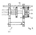
- Fig. 3 shows a molding machine according to FIG. 1 in a side view.
- the mold element 04 of the first type is here hidden by the frame 02.
- Form element 03 and 04 of the first type rotate as known in alternation about the rotation axis 06.
- the media supply 08 is one of the mold elements 03, 04 of the first genus directly in front of the Media supply device 07 of the molding machine.
- the media supply device 08 of one of the mold elements 03, 04 of the first type is alternately connected to the media supply device 07 of the automatic molding machine.
- the connection of the feeders of the element 05 of the second type can be done as known.
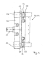
- Fig. 4 shows a connection device of a molding machine according to FIG. 1 between the media feeders 07, 08 of the molding machine and the formula element in detail in a side view.
- One of the form elements 03, 04 of the first type is in the aligned state directly on the frame 02 of the molding machine.
- the media supply device 07 of the automatic molding machine and the media supply device 08 of the relevant formula element are directly opposite.
- the media supply device 07 of the molding machine is designed as a continuous pipe connection through the frame 02.
- a displaceable tube 09 is provided as part of the connecting device.
- the sliding tube 09 can be each move over an actuator plate 10.
- the actuator plate 10 is actuated via the hydraulic 11.
- the connection of the media supply device 07 of the molding machine with the media supply device 08 of the relevant element element can now be secured by a closure device 12.
- the closure device 12 may have, for example, pneumatically or electrically operable flaps.
- FIG. 5 shows a further molding machine 30 having a first mold 31 and a second mold 32. Furthermore, the automatic molding machine 30 has a first mold element 33 of a first type and a second mold element 34 of the first type, which are arranged around a common axis of rotation 35 , wherein the axis of rotation 35 is rotatably mounted on the molding machine 30.
- first mold element 33 of a first type and a second mold element 34 of the first type which are arranged around a common axis of rotation 35 , wherein the axis of rotation 35 is rotatably mounted on the molding machine 30.
- the automatic molding machine 30 has a first mold element 36 of a second type and a second mold element 37 of the second type.
- At least one shaped element of the first type and one shaped element of the second type participate in the formation of the molds 31 and 32.
- the mold elements are arranged such that the two molds 31, 32 result from a transverse displacement of the mold elements 36, 37 in the direction of the mold elements 33, 34.
- the mold elements 33, 34 can swap their positions by rotation about their axis of rotation 35.
- the formation of the first mold 31 involves the mold element 36 and alternately the mold element 33 or 34
- the formation of the second mold 32 involves the formula element 37 and alternately the mold element 34 or 33.
- the molds 31, 32 can be formed simultaneously at the same time, or the molds 31, 32 are formed offset in time. This can be achieved for example by time-shifted transversal displacement of the mold elements 36, 37.
- the direction of rotation of the mold elements 33, 34 about the axis of rotation 35 is basically arbitrary.
- the shaping elements 33, 34 can rotate continuously around the rotation axis 35 in a clockwise direction, they can rotate continuously around the rotation axis 35 in a counterclockwise direction, but they can also rotate around the rotation axis 35 in an alternating clockwise and counterclockwise direction.
- FIG. 6 shows the shaped elements 33, 34, 36, 37 of the automatic molding machine 30 according to FIG. 5 .
- the jointly rotatable mold elements 33, 34 are designed as matrices and each have a hood 38.
- the shaped elements 36, 37 are designed as a male and have a core 39, 40 on.
- the first core 39 of the molding element 36 differs from the second core 40 of the molding element 37 with respect to its shape.
- the molding elements 36, 37 of the second type are designed differently with respect to their shape.
- the hoods 38 of the mold elements 33, 34 are, however, designed the same in this embodiment with respect to their shape.
- the automatic molding machine could also have two identical cores and two different hoods. Also arbitrary is whether the hoods or cores are rotatably provided in the center of the arrangement.
- the volume of the mold 31 in this embodiment is less than the volume of the mold 32.
- the mold 31 is therefore suitable for producing a first molding section 41.
- the second mold 32 has a larger volume than the mold 31 and is suitable for producing a second mold part section 42.
- the molding sections 41, 42 may differ, for example, by consistency, density and color and are firmly connected.
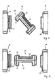
- FIGS. 7 to 14 show a manufacturing process of such a molding with two molding sections 41, 42.
- FIG. 7 shows an already foamed first molded part section 41 in the hood 38 of the molded element 34.
- the first molded part section 41 is already foamed and stabilized.
- the molds 31, 32 are then closed simultaneously. This is done by a transverse movement of the mold elements 36, 37 in the direction of the mold elements 33, 34.
- the mold 31 results from the mold elements 33, 36 and the mold 32 results from the mold elements 34, 37th
- Fig. 9 the molds 31 and 32 are closed, but not for the sake of clarity. To recognize here are the different shape cavities with respect to their shape. The different shape is due to the different cores 39, 40 ago.
- the molds 31, 32 While the molds 31, 32 are closed, they are foamed.
- the right mold 31 was originally empty and is foamed with a first molding portion 41.
- the left mold 32 was originally filled with the first mold part section 41 and is now foamed with the second mold part section 42. Because of the flatter core 40, the mold 32 results in a larger-volume cavity.
- the two molds 31, 32 After the two molds 31, 32 have been completely foamed and stabilized, they are opened again as shown in FIG .
- the first molded part section 41 just produced remains in the Hood 38 of the molding element 33 and the composite of the first molding section 41 and the second molding section 42 made in the left mold 32 remain on the core 40 of the molding element 37.
- the mold elements 36 and 37 are moved transversely away from the mold elements 33, 34 and thus the molds 31, 32 released again.
- the molding element 33 is located at the location of the molding element 34 and vice versa.
- the first mold part section 41 in the hood 38 of the mold element 33 now occupies the location of the first mold part section 41, as in FIG. 7 at the beginning of the production process, and is further processed in the next process step according to FIG. 8 ff .
- the composite of the first molding section 41 and the second molding section 42 on the core 40 of the molding element 37 was removed.
- the first mold 31 will now be in the next process step from the mold elements 34 and 36 and the mold 32 is formed in the following process steps from the mold elements 33 and 37.
- the formation of the forms 31, 32 alternately continues.
Landscapes
- Engineering & Computer Science (AREA)
- Mechanical Engineering (AREA)
- Manufacturing & Machinery (AREA)
- Moulds For Moulding Plastics Or The Like (AREA)
Applications Claiming Priority (1)
| Application Number | Priority Date | Filing Date | Title |
|---|---|---|---|
| DE200520019021 DE202005019021U1 (de) | 2005-12-05 | 2005-12-05 | Formteilautomat mit rotierender Form |
Publications (2)
| Publication Number | Publication Date |
|---|---|
| EP1792701A2 true EP1792701A2 (fr) | 2007-06-06 |
| EP1792701A3 EP1792701A3 (fr) | 2011-06-08 |
Family
ID=36202301
Family Applications (1)
| Application Number | Title | Priority Date | Filing Date |
|---|---|---|---|
| EP06011062A Withdrawn EP1792701A3 (fr) | 2005-12-05 | 2006-05-30 | Dispositif de moulage avec moule pouvant pivoter |
Country Status (2)
| Country | Link |
|---|---|
| EP (1) | EP1792701A3 (fr) |
| DE (1) | DE202005019021U1 (fr) |
Families Citing this family (2)
| Publication number | Priority date | Publication date | Assignee | Title |
|---|---|---|---|---|
| DE102006021021A1 (de) * | 2006-05-05 | 2007-11-15 | Krauss Maffei Gmbh | Verfahren zur Herstellung eines Mehrschichtteiles |
| DE102018211737B4 (de) * | 2018-07-13 | 2020-02-13 | Erlenbach Gmbh | Maschinensystem, Formteilmaschine, Werkzeugblock und Verfahren zum Ausrüsten einer Formteilmaschine |
Family Cites Families (2)
| Publication number | Priority date | Publication date | Assignee | Title |
|---|---|---|---|---|
| DE2709450B1 (de) * | 1977-03-04 | 1978-05-03 | Kurtz Fa Ph | Maschine zum zweistufigen Herstellen von geschaeumten Thermoplastformteilen |
| EP1647393A3 (fr) * | 2001-08-03 | 2006-05-10 | Krauss-Maffei Kunststofftechnik GmbH | Dispositif de serrage de moule pour une presse à injecter |
-
2005
- 2005-12-05 DE DE200520019021 patent/DE202005019021U1/de not_active Expired - Lifetime
-
2006
- 2006-05-30 EP EP06011062A patent/EP1792701A3/fr not_active Withdrawn
Also Published As
| Publication number | Publication date |
|---|---|
| DE202005019021U1 (de) | 2006-03-30 |
| EP1792701A3 (fr) | 2011-06-08 |
Similar Documents
| Publication | Publication Date | Title |
|---|---|---|
| DE69514615T2 (de) | Giessverfahren und Vorrichtung | |
| DE69826526T2 (de) | Verfahren und gerät zum formen eines zusammengesetzten gegenstands | |
| DE3639313A1 (de) | Rueckwaertig zu oeffnende formeinrichtung | |
| DE3519921A1 (de) | Giessform mit beheiztem angusskanal fuer spritzgiessen | |
| DE3213256A1 (de) | Verfahren zum herstellen eines ventilatorgitters | |
| CH342368A (de) | Verfahren und Maschine zur Herstellung von Flaschen aus plastischem Material | |
| DE10053199B4 (de) | Verfahren zum Herstellen eines Metallverbundstoff-Presslings | |
| EP3401037B1 (fr) | Moule destiné à la fabrication d'un noyau de coulé | |
| DE69319243T2 (de) | Verfahren und vorrichtung zum herstellen von thermoplastischen kunststoffschrauben | |
| WO2014173671A2 (fr) | Moule permettant de fabriquer un élément composite en fibre et en matière plastique, pourvu d'au moins un trou de ventilation dans lequel est disposée une tige d'éjection | |
| EP0074473B1 (fr) | Procédé et dispositif pour la fabrication de pièces de forme ou des objets en matière plastique | |
| WO2024120575A1 (fr) | Méthode de fabrication de rouleaux en plastique et moule | |
| DE19747573C2 (de) | Spritzeinheitsverbindungsvorrichtung für eine Mehrschichtspritzformmaschine | |
| DE2233395A1 (de) | Spritzgussform mit auswerfereinrichtung | |
| EP0464411A1 (fr) | Dispositif pour la production de tuyaux en matière plastique | |
| EP0484315A2 (fr) | Moule d'injection | |
| EP1792701A2 (fr) | Dispositif de moulage avec moule pouvant pivoter | |
| EP3697554A1 (fr) | Moule de coulée sous pression pour la coulée de carters-cylindres ou de parties inférieures de carters de vilebrequin | |
| DE102009031604A1 (de) | Sandgusswerkzeug | |
| DE60111611T2 (de) | Verfahren und vorrichtung zum spritzgiessen | |
| DE1552182B2 (de) | Vorrichtung zum Radialpressen von Verzahnungen | |
| DE202016103268U1 (de) | Auswurfvorrichtung für ein Werrkzeug zur Herstellung eines Formteils | |
| DE19536759C2 (de) | Verfahren zur Herstellung eines Rohrs | |
| DE10255993B4 (de) | Spritzgießwerkzeug und zugehöriges Verfahren | |
| EP2879854B1 (fr) | Unité de fermeture pour une machine de moulage par injection |
Legal Events
| Date | Code | Title | Description |
|---|---|---|---|
| PUAI | Public reference made under article 153(3) epc to a published international application that has entered the european phase |
Free format text: ORIGINAL CODE: 0009012 |
|
| AK | Designated contracting states |
Kind code of ref document: A2 Designated state(s): AT BE BG CH CY CZ DE DK EE ES FI FR GB GR HU IE IS IT LI LT LU LV MC NL PL PT RO SE SI SK TR |
|
| AX | Request for extension of the european patent |
Extension state: AL BA HR MK YU |
|
| PUAL | Search report despatched |
Free format text: ORIGINAL CODE: 0009013 |
|
| AK | Designated contracting states |
Kind code of ref document: A3 Designated state(s): AT BE BG CH CY CZ DE DK EE ES FI FR GB GR HU IE IS IT LI LT LU LV MC NL PL PT RO SE SI SK TR |
|
| AX | Request for extension of the european patent |
Extension state: AL BA HR MK YU |
|
| RIC1 | Information provided on ipc code assigned before grant |
Ipc: B29C 44/08 20060101ALI20110429BHEP Ipc: B29C 33/34 20060101ALI20110429BHEP Ipc: B29C 44/58 20060101AFI20070309BHEP |
|
| AKY | No designation fees paid | ||
| REG | Reference to a national code |
Ref country code: DE Ref legal event code: R108 Effective date: 20120215 |
|
| STAA | Information on the status of an ep patent application or granted ep patent |
Free format text: STATUS: THE APPLICATION IS DEEMED TO BE WITHDRAWN |
|
| 18D | Application deemed to be withdrawn |
Effective date: 20111209 |