EP1793127A1 - Unite de commande de pression de fluide et procede de commande - Google Patents
Unite de commande de pression de fluide et procede de commande Download PDFInfo
- Publication number
- EP1793127A1 EP1793127A1 EP06712005A EP06712005A EP1793127A1 EP 1793127 A1 EP1793127 A1 EP 1793127A1 EP 06712005 A EP06712005 A EP 06712005A EP 06712005 A EP06712005 A EP 06712005A EP 1793127 A1 EP1793127 A1 EP 1793127A1
- Authority
- EP
- European Patent Office
- Prior art keywords
- actuator
- movement
- motor
- operating range
- fluid
- Prior art date
- Legal status (The legal status is an assumption and is not a legal conclusion. Google has not performed a legal analysis and makes no representation as to the accuracy of the status listed.)
- Granted
Links
Images


Classifications
-
- B—PERFORMING OPERATIONS; TRANSPORTING
- B23—MACHINE TOOLS; METAL-WORKING NOT OTHERWISE PROVIDED FOR
- B23B—TURNING; BORING
- B23B31/00—Chucks; Expansion mandrels; Adaptations thereof for remote control
- B23B31/02—Chucks
- B23B31/24—Chucks characterised by features relating primarily to remote control of the gripping means
- B23B31/30—Chucks characterised by features relating primarily to remote control of the gripping means using fluid-pressure means in the chuck
- B23B31/302—Hydraulic equipment, e.g. pistons, valves, rotary joints
-
- F—MECHANICAL ENGINEERING; LIGHTING; HEATING; WEAPONS; BLASTING
- F15—FLUID-PRESSURE ACTUATORS; HYDRAULICS OR PNEUMATICS IN GENERAL
- F15B—SYSTEMS ACTING BY MEANS OF FLUIDS IN GENERAL; FLUID-PRESSURE ACTUATORS, e.g. SERVOMOTORS; DETAILS OF FLUID-PRESSURE SYSTEMS, NOT OTHERWISE PROVIDED FOR
- F15B11/00—Servomotor systems without provision for follow-up action; Circuits therefor
- F15B11/02—Systems essentially incorporating special features for controlling the speed or actuating force of an output member
- F15B11/04—Systems essentially incorporating special features for controlling the speed or actuating force of an output member for controlling the speed
-
- B—PERFORMING OPERATIONS; TRANSPORTING
- B23—MACHINE TOOLS; METAL-WORKING NOT OTHERWISE PROVIDED FOR
- B23B—TURNING; BORING
- B23B31/00—Chucks; Expansion mandrels; Adaptations thereof for remote control
- B23B31/02—Chucks
- B23B31/24—Chucks characterised by features relating primarily to remote control of the gripping means
- B23B31/30—Chucks characterised by features relating primarily to remote control of the gripping means using fluid-pressure means in the chuck
-
- F—MECHANICAL ENGINEERING; LIGHTING; HEATING; WEAPONS; BLASTING
- F15—FLUID-PRESSURE ACTUATORS; HYDRAULICS OR PNEUMATICS IN GENERAL
- F15B—SYSTEMS ACTING BY MEANS OF FLUIDS IN GENERAL; FLUID-PRESSURE ACTUATORS, e.g. SERVOMOTORS; DETAILS OF FLUID-PRESSURE SYSTEMS, NOT OTHERWISE PROVIDED FOR
- F15B11/00—Servomotor systems without provision for follow-up action; Circuits therefor
- F15B11/02—Systems essentially incorporating special features for controlling the speed or actuating force of an output member
- F15B11/04—Systems essentially incorporating special features for controlling the speed or actuating force of an output member for controlling the speed
- F15B11/046—Systems essentially incorporating special features for controlling the speed or actuating force of an output member for controlling the speed depending on the position of the working member
- F15B11/048—Systems essentially incorporating special features for controlling the speed or actuating force of an output member for controlling the speed depending on the position of the working member with deceleration control
-
- F—MECHANICAL ENGINEERING; LIGHTING; HEATING; WEAPONS; BLASTING
- F15—FLUID-PRESSURE ACTUATORS; HYDRAULICS OR PNEUMATICS IN GENERAL
- F15B—SYSTEMS ACTING BY MEANS OF FLUIDS IN GENERAL; FLUID-PRESSURE ACTUATORS, e.g. SERVOMOTORS; DETAILS OF FLUID-PRESSURE SYSTEMS, NOT OTHERWISE PROVIDED FOR
- F15B21/00—Common features of fluid actuator systems; Fluid-pressure actuator systems or details thereof, not covered by any other group of this subclass
- F15B21/08—Servomotor systems incorporating electrically operated control means
- F15B21/087—Control strategy, e.g. with block diagram
-
- F—MECHANICAL ENGINEERING; LIGHTING; HEATING; WEAPONS; BLASTING
- F15—FLUID-PRESSURE ACTUATORS; HYDRAULICS OR PNEUMATICS IN GENERAL
- F15B—SYSTEMS ACTING BY MEANS OF FLUIDS IN GENERAL; FLUID-PRESSURE ACTUATORS, e.g. SERVOMOTORS; DETAILS OF FLUID-PRESSURE SYSTEMS, NOT OTHERWISE PROVIDED FOR
- F15B9/00—Servomotors with follow-up action, e.g. obtained by feed-back control, i.e. in which the position of the actuated member conforms with that of the controlling member
- F15B9/02—Servomotors with follow-up action, e.g. obtained by feed-back control, i.e. in which the position of the actuated member conforms with that of the controlling member with servomotors of the reciprocatable or oscillatable type
- F15B9/04—Servomotors with follow-up action, e.g. obtained by feed-back control, i.e. in which the position of the actuated member conforms with that of the controlling member with servomotors of the reciprocatable or oscillatable type controlled by varying the output of a pump with variable capacity
-
- G—PHYSICS
- G05—CONTROLLING; REGULATING
- G05D—SYSTEMS FOR CONTROLLING OR REGULATING NON-ELECTRIC VARIABLES
- G05D3/00—Control of position or direction
- G05D3/10—Control of position or direction without using feedback
-
- F—MECHANICAL ENGINEERING; LIGHTING; HEATING; WEAPONS; BLASTING
- F15—FLUID-PRESSURE ACTUATORS; HYDRAULICS OR PNEUMATICS IN GENERAL
- F15B—SYSTEMS ACTING BY MEANS OF FLUIDS IN GENERAL; FLUID-PRESSURE ACTUATORS, e.g. SERVOMOTORS; DETAILS OF FLUID-PRESSURE SYSTEMS, NOT OTHERWISE PROVIDED FOR
- F15B19/00—Testing; Calibrating; Fault detection or monitoring; Simulation or modelling of fluid-pressure systems or apparatus not otherwise provided for
- F15B19/005—Fault detection or monitoring
-
- F—MECHANICAL ENGINEERING; LIGHTING; HEATING; WEAPONS; BLASTING
- F15—FLUID-PRESSURE ACTUATORS; HYDRAULICS OR PNEUMATICS IN GENERAL
- F15B—SYSTEMS ACTING BY MEANS OF FLUIDS IN GENERAL; FLUID-PRESSURE ACTUATORS, e.g. SERVOMOTORS; DETAILS OF FLUID-PRESSURE SYSTEMS, NOT OTHERWISE PROVIDED FOR
- F15B2211/00—Circuits for servomotor systems
- F15B2211/20—Fluid pressure source, e.g. accumulator or variable axial piston pump
- F15B2211/205—Systems with pumps
- F15B2211/20507—Type of prime mover
- F15B2211/20515—Electric motor
-
- F—MECHANICAL ENGINEERING; LIGHTING; HEATING; WEAPONS; BLASTING
- F15—FLUID-PRESSURE ACTUATORS; HYDRAULICS OR PNEUMATICS IN GENERAL
- F15B—SYSTEMS ACTING BY MEANS OF FLUIDS IN GENERAL; FLUID-PRESSURE ACTUATORS, e.g. SERVOMOTORS; DETAILS OF FLUID-PRESSURE SYSTEMS, NOT OTHERWISE PROVIDED FOR
- F15B2211/00—Circuits for servomotor systems
- F15B2211/20—Fluid pressure source, e.g. accumulator or variable axial piston pump
- F15B2211/205—Systems with pumps
- F15B2211/2053—Type of pump
- F15B2211/20538—Type of pump constant capacity
-
- F—MECHANICAL ENGINEERING; LIGHTING; HEATING; WEAPONS; BLASTING
- F15—FLUID-PRESSURE ACTUATORS; HYDRAULICS OR PNEUMATICS IN GENERAL
- F15B—SYSTEMS ACTING BY MEANS OF FLUIDS IN GENERAL; FLUID-PRESSURE ACTUATORS, e.g. SERVOMOTORS; DETAILS OF FLUID-PRESSURE SYSTEMS, NOT OTHERWISE PROVIDED FOR
- F15B2211/00—Circuits for servomotor systems
- F15B2211/60—Circuit components or control therefor
- F15B2211/63—Electronic controllers
- F15B2211/6303—Electronic controllers using input signals
- F15B2211/6306—Electronic controllers using input signals representing a pressure
- F15B2211/6309—Electronic controllers using input signals representing a pressure the pressure being a pressure source supply pressure
-
- F—MECHANICAL ENGINEERING; LIGHTING; HEATING; WEAPONS; BLASTING
- F15—FLUID-PRESSURE ACTUATORS; HYDRAULICS OR PNEUMATICS IN GENERAL
- F15B—SYSTEMS ACTING BY MEANS OF FLUIDS IN GENERAL; FLUID-PRESSURE ACTUATORS, e.g. SERVOMOTORS; DETAILS OF FLUID-PRESSURE SYSTEMS, NOT OTHERWISE PROVIDED FOR
- F15B2211/00—Circuits for servomotor systems
- F15B2211/60—Circuit components or control therefor
- F15B2211/63—Electronic controllers
- F15B2211/6303—Electronic controllers using input signals
- F15B2211/633—Electronic controllers using input signals representing a state of the prime mover, e.g. torque or rotational speed
-
- F—MECHANICAL ENGINEERING; LIGHTING; HEATING; WEAPONS; BLASTING
- F15—FLUID-PRESSURE ACTUATORS; HYDRAULICS OR PNEUMATICS IN GENERAL
- F15B—SYSTEMS ACTING BY MEANS OF FLUIDS IN GENERAL; FLUID-PRESSURE ACTUATORS, e.g. SERVOMOTORS; DETAILS OF FLUID-PRESSURE SYSTEMS, NOT OTHERWISE PROVIDED FOR
- F15B2211/00—Circuits for servomotor systems
- F15B2211/60—Circuit components or control therefor
- F15B2211/665—Methods of control using electronic components
- F15B2211/6651—Control of the prime mover, e.g. control of the output torque or rotational speed
-
- F—MECHANICAL ENGINEERING; LIGHTING; HEATING; WEAPONS; BLASTING
- F15—FLUID-PRESSURE ACTUATORS; HYDRAULICS OR PNEUMATICS IN GENERAL
- F15B—SYSTEMS ACTING BY MEANS OF FLUIDS IN GENERAL; FLUID-PRESSURE ACTUATORS, e.g. SERVOMOTORS; DETAILS OF FLUID-PRESSURE SYSTEMS, NOT OTHERWISE PROVIDED FOR
- F15B2211/00—Circuits for servomotor systems
- F15B2211/60—Circuit components or control therefor
- F15B2211/665—Methods of control using electronic components
- F15B2211/6654—Flow rate control
-
- F—MECHANICAL ENGINEERING; LIGHTING; HEATING; WEAPONS; BLASTING
- F15—FLUID-PRESSURE ACTUATORS; HYDRAULICS OR PNEUMATICS IN GENERAL
- F15B—SYSTEMS ACTING BY MEANS OF FLUIDS IN GENERAL; FLUID-PRESSURE ACTUATORS, e.g. SERVOMOTORS; DETAILS OF FLUID-PRESSURE SYSTEMS, NOT OTHERWISE PROVIDED FOR
- F15B2211/00—Circuits for servomotor systems
- F15B2211/70—Output members, e.g. hydraulic motors or cylinders or control therefor
- F15B2211/705—Output members, e.g. hydraulic motors or cylinders or control therefor characterised by the type of output members or actuators
- F15B2211/7051—Linear output members
- F15B2211/7053—Double-acting output members
Definitions
- This invention relates to fluid pressure units equipped with an actuator to which fluid discharged from a fluid pump is supplied and control methods for the fluid pressure units.
- fluid pressure units of such kind there is conventionally known one including a fixed displacement hydraulic pump, an adjustable speed motor for driving the hydraulic pump, an actuator, such as a hydraulic cylinder, to which working fluid discharged from the hydraulic pump is supplied through a discharge line, an operating selector valve for selectively providing and interrupting fluid communication into the discharge line between the hydraulic pump and the actuator, a controller for controlling the adjustable speed motor, and a pressure sensor for detecting the pressure of the discharge line for the hydraulic pump (see, for example, Patent Document 1).
- the controller is configured to control the rotational speed of the adjustable speed motor so that the pressure of the discharge line detected by the pressure sensor and the flow rate thereof calculated from the rotational speed of the adjustable speed motor can be a pressure and a flow rate both lying on a predetermined target pressure-flow rate curve.
- the fluid pressure unit is configured to control by itself the pressure and flow rate of fluid discharged from the hydraulic pump without externally receiving any pressure command signal and flow rate command signal. This eliminates the need to externally input a pressure command signal or a flow rate command signal and dispenses with any input signal line, thereby saving the trouble of the operator inputting commands for the pressure or the flow rate and simplifying the wiring.
- Patent Document 1 Unexamined Japanese Patent Publication No. 2001-90671
- a pressure reducing valve (21) is connected between a hydraulic pump (1) (a fluid pump) and, for example, a hydraulic cylinder (3) serving as an actuator and the pressure reduced by the pressure reducing valve (21) is set as the pressure for controlling the cylinder (3)
- the set pressure can be changed without any effect on the circuits extending from the pump (1) towards the other actuators. Therefore, the surge pressure at the time the cylinder (3) reaches a stroke end (an movement end position) can be reduced to some degree.
- the cylinder (3) is a chuck cylinder for actuating, for example, a work chuck serving as an object to be actuated and allows the chuck to chuck a work through either extension or retraction of the cylinder (3).
- reference numeral (2) denotes a motor for driving the hydraulic pump.
- the motor (2) forms an oil pressure supply unit together with the hydraulic pump.
- Reference numeral (8) denotes a selector valve connected between the pump (1) and the cylinder (3).
- the selector valve (8) is configured to start the movement (extension or retraction) of the cylinder (3) through the selection of ports of the selector valve (8).
- the pressure loss produced at the pressure reducing valve (21) is determined, as shown in Figure 5, by the PRV set pressure set through the pressure reducing valve (PRV) regardless of the type of the oil pressure supply unit (which is used of a combination of an induction motor and a variable displacement pump and a combination of an adjustable speed motor (2) and a fixed displacement pump (1). If the unit set pressure set through the oil pressure supply unit is increased, the flow rate of fluid passing through the valve during the cylinder movement can be increased with a slight increase in differential pressure. In this case, however, the discharge rate of the unit is set with reference to the flow rate of fluid restricted by the pressure reducing valve (21).
- the unit set pressure in the oil pressure supply unit is set as the pressure of fluid to be supplied to the cylinder (3), as shown in Figure 7, the flow rate of fluid passing through the discharge line during the cylinder movement is increased, at a constant unit set pressure, by an amount corresponding to the pressure loss at the pressure reducing valve (21) that would be otherwise disposed. Since, however, an amount of pressure necessary to move the cylinder (3) itself exists, the flow rate cannot be increased up to the set flow rate. If the unit set pressure is increased to or above a necessary pressure only during movement of the cylinder (3), the flow rate during the movement can be increased up to the set flow rate. However, a corresponding amount of surge pressure is developed at the end of the movement, which leads to the cylinder (3) chucking the work with a pressure exceeding the necessary pressure.
- the present invention has been made in view of the foregoing points and its object is to satisfy both rapid movement of the actuator and reduction in the surge pressure at the end of movement of the actuator by improving the manner of controlling the fluid pressure unit.
- a first solution of the invention is a fluid pressure unit comprising: a fixed displacement fluid pump (1) configured to be driven by an adjustable speed motor (2) to discharge fluid; at least one actuator (3) for actuating an object to be actuated with a pressure of the fluid discharged from the fluid pump (1); and control means (12) for, upon the actuator (3) actuating the object to be actuated, imparting a teaching movement to the actuator (3) to determine an operating range of the actuator (3) based on the number of rotations of the motor (2) and, during subsequent movement of the actuator (3) to actuate the object to be actuated, rotating the motor (2) at a first speed until a preset deceleration start point short of the end of movement of the actuator (3) within the determined operating range and then rotating the motor (2) at a second speed lower than the first speed from the deceleration start point to the end of movement of the actuator (3).
- the actuator (3) when the actuator (3) actuates the object to be actuated, a teaching movement is imparted to the actuator (3) prior to the subsequent movement of the actuator (3) intended to actuate the object to be actuated.
- the operating range of the actuator (3) is determined based on the number of rotations of the motor (2).
- the motor (2) rotates at the first speed until the preset deceleration start point short of the end of movement of the actuator (3) within the determined operating range and then rotates at the second speed lower than the first speed from the deceleration start point to the end of movement of the actuator (3).
- the first speed can be set at a high speed to increase the operating speed of the actuator (3) and the second speed can be set at a low speed to slowly stop the movement of the actuator (3) and thereby reduce the increase in the surge pressure.
- a second solution of the invention is a fluid pressure unit comprising: a fixed displacement fluid pump (1) configured to be driven by an adjustable speed motor (2) to discharge fluid; at least one actuator (3) for actuating an object to be actuated with a pressure of the fluid discharged from the fluid pump (1); and control means (12) for, upon the actuator (3) actuating the object to be actuated, rotating the motor (2) at a first speed until a preset deceleration start point short of the end of movement of the actuator (3) within a predetermined operating range of the actuator (3) and then rotating the motor (2) at a second speed lower than the first speed from the deceleration start point to the end of movement of the actuator (3).
- control means (12) is configured to effect a learning control for correcting the operating range of the actuator (3) to a small extent when the surge pressure at the end of movement of the actuator (3) is equal to or greater than a set value and correcting the operating range of the actuator (3) to a large extent when the period of time from the deceleration start point to the end of movement of the actuator (3) is equal to or greater than a set value.
- the motor (3) rotates at the first speed until the preset deceleration start point short of the end of movement of the actuator (3) within the operating range of the actuator (3) and then rotates at the second speed lower than the first speed from the deceleration start point to the end of movement of the actuator (3). Then, the operating range of the actuator (3) is corrected based on the surge pressure at the end of movement of the actuator (3) and the period of time from the deceleration start point to the end of movement of the actuator (3).
- the operating range of the actuator (3) is corrected to a small extent if the surge pressure is equal to or greater than a set value, while the operating range of the actuator (3) is corrected to a large extent if the period of time until the end of movement of the actuator (3) is equal to or greater than a set value.
- the operating range of the actuator (3) is learned by correction. Therefore, without imparting of a teaching movement to the actuator (3), the first speed can be set at a high speed to increase the operating speed of the actuator (3) and the second speed can be set at a low speed to slowly stop the movement of the actuator (3) and thereby reduce the increase in the surge pressure.
- a third solution of the invention is directed to the fluid pressure unit of the first or second solution and characterized in that the object to be actuated is a chuck for chucking a work and the control means (12) is configured to store data on the operating range of the actuator (3) for each of plural types of works and, at every change of the work type, call up the operating range of the actuator (3) for the current work and control the actuator (3) based on the operating range.
- a fourth solution of the invention is directed to the fluid pressure unit of the second solution and characterized in that the control means (12) is configured to issue a warning when the operating range of the actuator (3) is smaller or greater than the predetermined operating range.
- a fifth solution of the invention is directed to the fluid pressure unit of the first or second solution and characterized in that the at least one actuator comprises a plurality of actuators.
- surgeless control can be exercised on the plurality of actuators.
- a sixth solution of the invention is directed to the fluid pressure unit of the first or second solution and characterized in that the control means (12) determines the operating range of the actuator (3) from a change towards an increase in the fluid pressure.
- the operating range of the actuator (3) is determined. Therefore, the operating range of the actuator (3) can be easily determined.
- a seventh solution of the invention is directed to the fluid pressure unit of the first or second solution and characterized in that the control means (12) determines the operating range of the actuator (3) from a change towards an increase in the drive current of the motor.
- the operating range of the actuator (3) is determined. Therefore, the operating range of the actuator (3) can be easily determined.
- An eighth solution of the invention is a fluid pressure unit comprising: a fixed displacement fluid pump (1) configured to be driven by an adjustable speed motor (2) to discharge fluid; an actuator (3) for actuating an object to be actuated with a pressure of the fluid discharged from the fluid pump (1); and estimating means (12) for, upon the actuator (3) actuating the object to be actuated, estimating an operating range of the actuator (3) based on the number of rotations of the motor (2).
- the actuator (3) when the fixed displacement fluid pump (1) is driven by the adjustable speed motor (2) to discharge fluid, the actuator (3) is operated by a pressure of the fluid discharged from the fluid pump (1) to actuate the object to be actuated.
- the operating range of the actuator (3) is estimated based on the number of rotations of the motor (2). Therefore, the operating range of the actuator (3) can be easily estimated.
- a ninth solution of the invention is directed to a method for controlling a fluid pressure unit including a fixed displacement fluid pump (1) configured to be driven by an adjustable speed motor (2) to discharge fluid and at least one actuator (3) for actuating an object to be actuated with a pressure of the fluid discharged from the fluid pump (1).
- a teaching movement is imparted to the actuator (3) to determine an operating range of the actuator (3) based on the number of rotations of the motor (2) and during subsequent movement of the actuator (3) to actuate the object to be actuated, the motor (2) is rotated at a first speed until a preset deceleration start point short of the end of movement of the actuator (3) within the determined operating range and the motor (2) is then rotated at a second speed lower than the first speed from the deceleration start point to the end of movement of the actuator (3).
- a tenth solution of the invention is directed to a method for controlling a fluid pressure unit including a fixed displacement fluid pump (1) configured to be driven by an adjustable speed motor (2) to discharge fluid and at least one actuator (3) for actuating an object to be actuated with a pressure of the fluid discharged from the fluid pump (1).
- the motor (2) upon the actuator (3) actuating the object to be actuated, the motor (2) is rotated at a first speed until a preset deceleration start point short of the end of movement of the actuator (3) within a predetermined operating range of the actuator (3) and the motor (2) is then rotated at a second speed lower than the first speed from the deceleration start point to the end of movement of the actuator (3).
- the operating range of the actuator (3) is corrected to a small extent.
- the period of time from the deceleration start point to the end of movement of the actuator (3) is equal to or greater than a set value, the operating range of the actuator (3) is corrected to a large extent.
- a teaching movement is previously imparted to the actuator to determine its operating range from the number of rotations of the motor and during movement of the actuator to actuate the object to be actuated after the teaching movement, the motor is rotated at a high speed until the preset deceleration start point short of the end of movement of the actuator within the operating range thereof and then rotated at a low speed from the deceleration start point to the end of movement of the actuator. This concurrently provides rapid movement of the actuator and reduction in surge pressure.
- the motor is rotated at a high speed until the preset deceleration start point short of the end of movement of the actuator within the predetermined operating range thereof and then rotated at a low speed from the deceleration start point to the end of movement of the actuator, and the operating range of the actuator is corrected based on the surge pressure at the end of movement of the actuator and the period of time from the deceleration start point to the end of movement of the actuator.
- the operating range of the actuator can be learned by correction. Therefore, without imparting of a teaching movement to the actuator, rapid movement of the actuator and reduction in surge pressure can be concurrently provided.
- the object to be actuated is a chuck for chucking a work
- data on the operating range of the actuator determined through a teaching movement or a learning control is stored for each of plural types of works and the operating range of the actuator for the current work after the type change is called up to control the actuator based on the operating range.
- the actuator comprises a plurality of actuators, surgeless control can be exercised on the plurality of actuators.
- the operating range of the actuator is determined from a change towards an increase in the fluid pressure, the operating range of the actuator can be easily determined.
- the operating range of the actuator is determined from a change towards an increase in the drive current of the motor, the operating range of the actuator can be easily determined.
- the operating range of the actuator during its actuation of the object to be actuated is estimated based on the number of rotations of the adjustable speed motor, the operating range of the actuator can be easily estimated.
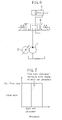
- FIG 2 shows a hydraulic unit (A) (fluid pressure unit) according to an embodiment of the present invention.
- the hydraulic unit (A) is used for a machine tool, such as a machining center, which is the main machine for the unit.
- the machine tool has a plurality of holders (obj ects to be actuated) for fixing a work or a tool, such as a chuck, a tailstock clamp and a tool post clamp, and these holders are actuated by associated actuators provided in the hydraulic unit (A).
- reference numeral (1) denotes a hydraulic pump (fluid pump) for discharging operating oil which is fluid
- reference numeral (2) denotes a motor for driving the hydraulic pump (1).
- the hydraulic pump (1) is formed of a fixed displacement pump such as a gear pump, a trochoid pump, a vane pump or a piston pump.
- the motor (2) is formed of an adjustable speed motor such as a switched reluctance motor (SRM) or an interior permanent magnet synchronous motor (IPMSM).
- a rotational speed control encoder (not shown) built in the adjustable speed motor (2) detects the motor rotational speed corresponding to the discharge rate of the hydraulic pump (1).
- Reference numeral (3) denotes a hydraulic cylinder (chuck cylinder) serving as an actuator for the chuck, to which operating oil discharged from the hydraulic pump (1) is supplied.
- the hydraulic cylinder (3) has a closing chamber (4) and an opening chamber (5) which are partitioned by a piston (3a) and both able to be supplied with operating oil discharged from the hydraulic pump (1).
- the hydraulic cylinder (3) Upon supply of the operating oil to the closing chamber (4), the hydraulic cylinder (3) extends to make a closing operation for closing the chuck.
- the hydraulic cylinder (3) unlike the closing operation, retracts to make an opening operation for opening the chuck.
- the chuck has a closing motion using mode in which it chucks a work from the outside when closed and an opening motion using mode in which it chucks a work from the inside when opened.
- the hydraulic cylinder (3) is used in both the two using modes. Specifically, in the closing motion using mode, the closing operation of the hydraulic cylinder (3) allows the chuck to chuck a work from the outside, while in the opening motion using mode, the opening operation of the hydraulic cylinder (3) allows the chuck to chuck a work from the inside.
- the closing chamber (4) and the opening chamber (5) of the hydraulic cylinder (3) are connected through hydraulic passages (7) to the discharge part of the hydraulic pump (1) and a tank (9).
- the hydraulic passages (7) are provided with an operating selector valve (8) for selectively providing and interrupting fluid communication into the hydraulic passages (7).
- the operating selector valve (8) is formed of a four-port three-position spring-loaded center-guided solenoid selector valve having first and second solenoids (8a, 8b). Out of the four ports, port A is connected to the opening chamber (5) of the hydraulic cylinder (3), port B is connected to the closing chamber (4) of the hydraulic cylinder (3), port P is connected to the discharge part of the hydraulic pump (1) and port R is connected to the tank (9).
- the operating selector valve (8) has three selective valve positions: a neutral position, a first position to which it is switched by an ON operation of the first solenoid (8a) and a second position to which it is switched by an ON operation of the second solenoid (8b).
- a neutral position When the valve position is in the neutral position, the four ports are all in interrupted fluid communication.
- port P When the valve position is in the first position, port P is connected to port A and port B is connected to port R.
- port P is connected to port B and port A is connected to port R.
- the discharge line for the hydraulic pump (1) is connected to circuits for the other hydraulic actuators (not shown) such as a tailstock clamp and a tool post clamp to operate the other hydraulic actuators.
- the operations of the two solenoids (8a, 8b) of the operating selector valve (8) and the motor (2) are controlled by a controller (12).
- the controller (12) receives output signals of a pressure sensor (13) for detecting the pressure of the discharge line for the hydraulic pump (1).
- Reference numeral (15) denotes a main machine control panel for controlling the machine tool.
- a spindle selection signal for giving an instruction to actuate the chuck is input from the main machine control panel (15) to the controller (12).
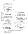
- step S1 a switching instruction is issued to one of the solenoids (8a, 8b) of the operating selector valve (8) to change the selector valve (8) from its neutral position to either one of the first and second positions and reset a stroke counter for the cylinder (3), i.e., a counter for integrating the number of pulses given from the encoder built in the motor (2).
- step S2 it is determined whether a work data flag is ON or OFF.
- the work data flag is for determining the existence or absence of a change in the operating stroke of the cylinder (3) involved in a change of work type.
- the flag is turned ON according to an instruction from the main machine.
- step S3 the motor (2) is first rotated at a preset rotational speed for stroke teaching to move the cylinder (3) to allow the chuck to chuck the work (impart a teaching movement to the cylinder (3)).
- This movement of the cylinder (3) is for teaching, the rotational speed for stroke teaching is a fixed rotational speed and a low speed is normally employed as the rotational speed (see (I) in Figure 3 ).
- the rotational speed for stroke teaching may be set at a high speed.
- step S3 the control proceeds to step S4 and integrates the number of pulses given from the encoder built in the motor (2) to count the operating stroke of the cylinder (3).
- step S5 it is determined whether the discharge line pressure detected by the pressure sensor (13) is increased up to a predetermined value. This determination is to determine, after the movement of the cylinder (3) ends with the chucking of the work by the chuck, whether this has caused an increase in the pressure of the discharge line. If the determination is NO, the control returns to step S3 and continues to count the operating stroke. If the determination is YES, the control proceeds to step S6 and records the stroke corresponding to the number of pulses integrated up to that time in step S4 as a necessary stroke for chucking a current work.
- step S7 because of the end of the teaching movement, the work data flag is turned OFF and, then, the actuation is ended.
- step S8 the motor (2) is rotated at a preset rotational speed for movement.
- the rotational speed for movement refers to a first speed in the present invention and is set at a high rotational speed (see (II) in Figure 3 ) in order to increase the operating speed of the cylinder (3).
- step S9 as in step S4, the number of pulses from the encoder built in the motor (2) is integrated to count the operating stroke of the cylinder (3).
- step S10 it is determined from the integrated number of pulses whether the operating stroke of the cylinder (3) has reached a deceleration start point (deceleration point).
- the deceleration start point is determined by previously setting the deceleration period (for example, at 0.1 seconds) and determining how many number of pulses it takes to complete the deceleration so that the cylinder (3) can reach in the deceleration period an movement end position obtained from the necessary stroke for chucking the current work recorded in step S6. As the rotational speed for movement is higher, the deceleration start point is set farther away from the movement end position.
- step S10 If the operating stroke of the cylinder (3) does not reach the deceleration start point and, therefore, the determination in step S10 is NO, the control returns to step S8, continues the rotation of the motor (2) at the rotational speed for movement to move the cylinder (3) and continues to count the stroke.
- step S 11 a deceleration processing is carried out in step S 11 with a time constant based the preset deceleration period to rotate the motor (2) at a rotational speed for deceleration in order to decelerate the movement of the cylinder (3) until its end.
- the rotational speed for deceleration refers to a second speed in the present invention and is set at an extremely low rotational speed lower than the rotational speed for movement (and the rotational speed for stroke teaching) (see (III) in Figure 3 ).
- step S12 determines whether the discharge line pressure detected by the pressure sensor (13) is increased up to a predetermined value.
- step S12 determines whether the chuck has chucked the work and the operating stroke of the cylinder (3) is completed. Then, the actuation is ended.
- the controller (12) imparts, upon the cylinder (3) actuating the chuck, a teaching movement to the cylinder (3) to determine the operating stroke of the cylinder (3) through the movement thereof based on the number of rotations of the motor (2) (the integrated number of pulses) and, during a subsequent surgeless movement of the cylinder (3) to actually actuate the chuck, rotates the motor (2) at the rotational speed for movement (first speed) until the deceleration start point just short of the end of movement of the cylinder (3) within the determined operating stroke and then rotates the motor (2) at the rotational speed for deceleration (second speed) lower than the rotational speed for movement from the deceleration start point to the end of movement of the cylinder (3).
- the controller (12) determines the operating stroke of the cylinder (3) by whether the discharge line pressure has changed and increased up to the predetermined value.
- the controller (12) constitutes an estimating means for, upon the cylinder (3) actuating the chuck, estimating the operating stroke based on the number of rotations of the motor (2) (the integrated number of pulses).
- an instruction signal for actuating the chuck is input from the main machine control panel (15) to the controller (12) of the hydraulic unit (A)
- a switching instruction is output to one of the solenoids (8a, 8b) of the operating selector valve (8) so that the selector valve (8) is switched from its neutral position to the either one of the first and second positions.
- the counter for integrating the number of pulses from the encoder built in the motor (2) is reset.
- a teaching movement is first imparted to the cylinder (3): the motor (2) is rotated at the rotational speed for stroke teaching so that the cylinder (3) moves to allow the chuck to chuck the work. With the rotation of the motor (2), the number of pulses from the encoder built in the motor (2) is integrated so that the operating stroke of the cylinder (3) is counted. Then, when the discharge line pressure detected by the pressure sensor (13) is increased up to the predetermined value, the stroke corresponding to the number of pulses integrated up to that time is recorded as a necessary stroke for chucking the current work and the operating stroke of the cylinder (3) is determined based on the number of rotations of the motor (2) (the integrated number of pulses).
- the motor (2) is rotated at a high rotational speed for movement to move the cylinder (3).
- the number of pulses from the encoder built in the motor (2) is integrated so that the operating stroke of the cylinder (3) is counted.
- the motor (2) is rotated at a low rotational speed for deceleration to decelerate the movement of the cylinder (3).
- the discharge line pressure detected by the pressure sensor (13) increases up to the predetermined value. Therefore, the operating stroke of the cylinder (3) is completed so that the chuck has chucked the work. Then, the work is processed by the main machine as it is chucked by the chuck.
- the teaching movement is imparted once each time the work type changes.
- a teaching movement is first imparted to the cylinder (3) to record the operating stroke of the cylinder (3). Then, during the actual chucking of the chuck, the deceleration start point is set based on the operating stroke of the cylinder (3) obtained by the teaching movement. When the cylinder (3) reaches the deceleration start point, the movement of the cylinder (3) is decelerated. Therefore, during the teaching movement, as shown in Figure 3, the set flow rate is reduced down to the flow rate (I) with the unit set pressure kept constant, whereby the motor rotational speed necessary to move the cylinder (3) is set at the rotational speed for stroke teaching.
- the unit set pressure is increased to move the cylinder (3) at the set flow rate (II). Then, the cylinder (3) is decelerated from the deceleration start point to the end of the movement. At the time when the chuck actually chucks the work, the unit set pressure is set at a state that the flow rate is substantially zero (III), thereby enabling the chuck to chuck the work with a soft touch. This reduces the development of a surge pressure involved in chucking.
- the motor (2) can be rotated at a high rotational speed for movement to move the cylinder (3) at a high speed, which correspondingly shortens the operating time of the cylinder (3).
- the cylinder operating time can be shortened 30% to 50% and the surge pressure can be reduced down to 0.1 MPa or less.
- the teaching movement is imparted not only to the cylinder (3) for actuating the chuck but also to the actuator for actuating a tailstock clamp and the actuator for actuating a tool post clamp.
- a multi-spindle surgeless control can be exercised in the machining tool.
- the fixed displacement hydraulic pump (1) is combined with the adjustable speed motor (2) and the operating stroke of the cylinder (3) is recorded by integrating the number of pulses from the rotational speed control encoder in the adjustable speed motor (2) through the teaching movement, the operating stroke of the cylinder (3) can be easily estimated based on the number of rotations of the motor (2) (the integrated number of pulses).
- the present invention is not limited to the above embodiment and includes the following other embodiments.
- the operating stroke of the cylinder (3) is determined from a change towards an increase in the discharge line pressure for both the teaching movement and the surgeless movement (actual chucking movement), it may be determined instead from a change towards an increase in the drive current of the motor (2).
- the operating stroke of the cylinder (3) is recorded through a teaching movement for a work and the recorded stroke is used during actual process of the work.
- the operating stroke of the cylinder (3) may be leaning controlled.
- the motor (2) is rotated at the rotational speed for movement (first speed) until the deceleration start point short of the end of movement of the cylinder (3) within the predetermined operating stroke and then rotated at the rotational speed for deceleration (second speed) lower than the rotational speed for movement from the deceleration start point to the end of movement of the cylinder (3).
- the controller (12) corrects the operating stroke of the cylinder (3) based on the surge pressure at the end of movement of the cylinder (3) and the period of time from the deceleration start point to the end of movement of the cylinder (3). Specifically, if the surge pressure at the end of movement of the cylinder (3) is equal to or greater than a set value, the operating stroke of the cylinder (3) is corrected to a small extent. Alternatively, if the period of time from the deceleration start point to the end of movement is equal to or greater than a set value, the operating stroke of the cylinder (3) is corrected to a large extent.
- the operating stroke of the cylinder (3) may be recorded for every work type and, at every change of the work type, the data for a current work may be called up to control the cylinder (3) based on the data.
- the controller (12) may issue a warning.
- the controller (12) may issue a warning.
- any hydraulic actuator other than the hydraulic cylinder (3) may be used.
- the present invention may be applied to systems other than machining tools and to fluid pressure units using fluids other than operating oil.
- the present invention is useful for fluid pressure units equipped with a fixed displacement fluid pump driven by an adjustable speed motor and an actuator for actuating an object to be actuated, because it concurrently provides rapid movement of the actuator and reduction in surge pressure.
Landscapes
- Engineering & Computer Science (AREA)
- Mechanical Engineering (AREA)
- Physics & Mathematics (AREA)
- Fluid Mechanics (AREA)
- General Engineering & Computer Science (AREA)
- Chemical & Material Sciences (AREA)
- Analytical Chemistry (AREA)
- General Physics & Mathematics (AREA)
- Automation & Control Theory (AREA)
- Fluid-Pressure Circuits (AREA)
Applications Claiming Priority (2)
| Application Number | Priority Date | Filing Date | Title |
|---|---|---|---|
| JP2005027973A JP4356623B2 (ja) | 2005-02-03 | 2005-02-03 | 流体圧ユニット及び流体圧ユニットの制御方法 |
| PCT/JP2006/300759 WO2006082711A1 (fr) | 2005-02-03 | 2006-01-19 | Unite de commande de pression de fluide et procede de commande |
Publications (3)
| Publication Number | Publication Date |
|---|---|
| EP1793127A1 true EP1793127A1 (fr) | 2007-06-06 |
| EP1793127A4 EP1793127A4 (fr) | 2012-05-30 |
| EP1793127B1 EP1793127B1 (fr) | 2020-03-04 |
Family
ID=36777100
Family Applications (1)
| Application Number | Title | Priority Date | Filing Date |
|---|---|---|---|
| EP06712005.5A Expired - Lifetime EP1793127B1 (fr) | 2005-02-03 | 2006-01-19 | Unite de commande de pression de fluide et procede de commande |
Country Status (7)
| Country | Link |
|---|---|
| US (1) | US7610754B2 (fr) |
| EP (1) | EP1793127B1 (fr) |
| JP (1) | JP4356623B2 (fr) |
| KR (2) | KR100852336B1 (fr) |
| CN (1) | CN1993557B (fr) |
| ES (1) | ES2787248T3 (fr) |
| WO (1) | WO2006082711A1 (fr) |
Cited By (6)
| Publication number | Priority date | Publication date | Assignee | Title |
|---|---|---|---|---|
| EP2322808A3 (fr) * | 2009-11-10 | 2014-02-19 | Sumitomo Precision Products Co., Ltd. | Actionneur électro-hydrostatique avec méchanisme d'amortissement, et dispositif d'entraînement et procédé de contrôle utilisant un tel actionneur |
| AT518192A1 (de) * | 2016-01-22 | 2017-08-15 | Engel Austria Gmbh | Hydraulikvorrichtung für eine Formgebungsmaschine |
| EP3241744A4 (fr) * | 2015-02-17 | 2018-01-03 | Sumitomo Precision Products Co., Ltd. | Système d'actionneur électro-hydrostatique destiné à lever et abaisser un train d'atterrissage d'aéronef |
| EP3309406A1 (fr) * | 2016-10-17 | 2018-04-18 | A S S F A L G Qualitätshydraulik GmbH & Co. KG | Agrégat hydraulique |
| EP3311997A1 (fr) * | 2016-10-18 | 2018-04-25 | Automation, Press and Tooling, A.P. & T AB | Presse servo-hydraulique |
| EP3936277A1 (fr) * | 2020-07-09 | 2022-01-12 | RoboJob N.V. | Dispositif hydraulique de serrage de pièce |
Families Citing this family (18)
| Publication number | Priority date | Publication date | Assignee | Title |
|---|---|---|---|---|
| JP4245065B2 (ja) | 2007-06-07 | 2009-03-25 | ダイキン工業株式会社 | 流体圧ユニット |
| US20100101785A1 (en) | 2008-10-28 | 2010-04-29 | Evgeny Khvoshchev | Hydraulic System and Method of Monitoring |
| DE102009021866A1 (de) * | 2009-05-19 | 2010-11-25 | Sauer-Danfoss Gmbh & Co Ohg | Hydroantrieb mit einer unabhängigen Speisepumpe |
| EP2808109B1 (fr) * | 2013-05-28 | 2018-05-02 | HAWE Hydraulik SE | Système de serrage |
| US9164497B2 (en) * | 2013-10-01 | 2015-10-20 | The Boeing Company | Reluctance motor system |
| CN104454697B (zh) * | 2014-10-17 | 2016-08-24 | 北京航天益森风洞工程技术有限公司 | 大载荷快速插入机构高速驱动及定位方法 |
| US10164501B2 (en) | 2014-12-11 | 2018-12-25 | The Boeing Company | Reluctance motor with dual-pole rotor system |
| US9929623B2 (en) | 2014-12-11 | 2018-03-27 | The Boeing Company | Reluctance motor with virtual rotor |
| JP2017189820A (ja) * | 2016-04-11 | 2017-10-19 | Dmg森精機株式会社 | 油圧チャック装置 |
| CN108591139A (zh) * | 2018-03-13 | 2018-09-28 | 西安理工大学 | 一种液压动力卡盘夹紧力控制系统及夹紧力控制方法 |
| JP6851405B2 (ja) * | 2019-02-01 | 2021-03-31 | 大家原油壓工業有限公司 | 省エネ型油圧制御システム |
| JP7448739B2 (ja) | 2019-05-27 | 2024-03-13 | Smc株式会社 | チャック装置の駆動システム及びその制御方法 |
| CN110282562B (zh) * | 2019-06-03 | 2020-09-29 | 长沙中联消防机械有限公司 | 举高消防车臂架控制方法、系统及举高消防车 |
| JP7623108B2 (ja) * | 2019-06-20 | 2025-01-28 | ジョイ・グローバル・サーフェイス・マイニング・インコーポレーテッド | 自動ダンプ制御を備えた産業機械 |
| CN112692317A (zh) * | 2021-01-11 | 2021-04-23 | 南京信息职业技术学院 | 一种数控机床自适应夹紧系统及其控制方法 |
| DE102023202043B3 (de) * | 2023-03-07 | 2024-03-21 | Baumüller Nürnberg GmbH | Verfahren zum Betrieb eines Hydrauliksystems einer Industriemaschine |
| KR20250148075A (ko) | 2024-04-05 | 2025-10-14 | 박형수 | 수용성 리포좀 커큐민의 제조방법 |
| CN120969282A (zh) * | 2025-08-25 | 2025-11-18 | 浙江大学 | 一种电静液驱动作业系统能量效率优化方法和系统 |
Family Cites Families (20)
| Publication number | Priority date | Publication date | Assignee | Title |
|---|---|---|---|---|
| JPS5431876A (en) * | 1977-08-13 | 1979-03-08 | Fanuc Ltd | Position setting apparatus |
| US4399653A (en) * | 1980-03-14 | 1983-08-23 | Pylat Jr John A | Automatic adjusting deceleration control for a hydrostatically powered device |
| DE3148174A1 (de) | 1981-12-05 | 1983-06-09 | Robert Bosch Gmbh, 7000 Stuttgart | Elektrohydraulischer stellantrieb |
| JPS6298001A (ja) * | 1985-10-23 | 1987-05-07 | Nikki Denso Kk | 油圧出力制御機構 |
| JPS6374881A (ja) | 1987-07-31 | 1988-04-05 | 株式会社日立製作所 | 油圧エレベ−タ |
| JPH01172601A (ja) * | 1987-12-25 | 1989-07-07 | Shimizu Corp | 油圧回路の制御装置 |
| JPH02221702A (ja) * | 1989-02-22 | 1990-09-04 | Nireco Corp | 電気油圧サーボ装置 |
| JP3384411B2 (ja) * | 1992-06-25 | 2003-03-10 | カヤバ工業株式会社 | 舞台機構の制御装置 |
| JPH06292769A (ja) * | 1993-04-08 | 1994-10-21 | Kayaba Ind Co Ltd | 舞台機構の制御装置 |
| JP2505372B2 (ja) * | 1994-02-28 | 1996-06-05 | 浅井興産株式会社 | 学習機能付き液圧プレス機械 |
| JPH0826697A (ja) | 1994-07-19 | 1996-01-30 | Meikikou:Kk | 油圧式テーブルリフト装置と該装置におけるテーブル昇降速度の制御方法 |
| JP2648291B2 (ja) * | 1995-05-16 | 1997-08-27 | 有限会社ヒロタカエンジニアリング | スポット溶接機の電極駆動装置 |
| JP3220637B2 (ja) * | 1996-03-21 | 2001-10-22 | 日興電機工業株式会社 | 油圧パワーユニット装置 |
| JPH11327651A (ja) * | 1998-05-20 | 1999-11-26 | Dainippon Printing Co Ltd | 可動体の停止方法および停止機構 |
| JP2000039920A (ja) * | 1998-07-22 | 2000-02-08 | Kanto Auto Works Ltd | 複数軸の位置制御装置 |
| DE19842337A1 (de) * | 1998-09-16 | 2000-03-23 | Mannesmann Vdo Ag | Betätigungseinrichtung für ein Verdeck eines Cabrios |
| JP2000337316A (ja) * | 1999-03-25 | 2000-12-05 | Taiyo Ltd | ストロークセンサ付きシリンダ装置 |
| JP4635282B2 (ja) | 1999-09-24 | 2011-02-23 | ダイキン工業株式会社 | 自律形インバータ駆動油圧ユニット |
| JP3710376B2 (ja) * | 2000-12-20 | 2005-10-26 | 株式会社パブコ | 油圧パワーユニットの制御装置および方法 |
| JP2005195081A (ja) | 2004-01-06 | 2005-07-21 | Daikin Ind Ltd | 油圧ユニット |
-
2005
- 2005-02-03 JP JP2005027973A patent/JP4356623B2/ja not_active Expired - Fee Related
-
2006
- 2006-01-19 EP EP06712005.5A patent/EP1793127B1/fr not_active Expired - Lifetime
- 2006-01-19 KR KR1020077001965A patent/KR100852336B1/ko not_active Expired - Fee Related
- 2006-01-19 WO PCT/JP2006/300759 patent/WO2006082711A1/fr not_active Ceased
- 2006-01-19 KR KR1020087012102A patent/KR20080058499A/ko not_active Ceased
- 2006-01-19 ES ES06712005T patent/ES2787248T3/es not_active Expired - Lifetime
- 2006-01-19 US US11/658,023 patent/US7610754B2/en not_active Expired - Fee Related
- 2006-01-19 CN CN2006800005278A patent/CN1993557B/zh not_active Expired - Fee Related
Cited By (12)
| Publication number | Priority date | Publication date | Assignee | Title |
|---|---|---|---|---|
| EP2322808A3 (fr) * | 2009-11-10 | 2014-02-19 | Sumitomo Precision Products Co., Ltd. | Actionneur électro-hydrostatique avec méchanisme d'amortissement, et dispositif d'entraînement et procédé de contrôle utilisant un tel actionneur |
| US8701400B2 (en) | 2009-11-10 | 2014-04-22 | Sumitomo Precision Products Co., Ltd. | Electro-hydrostatic actuator excellent in snubbing characteristic, and drive device used for the same, and control method used for the same |
| EP3241744A4 (fr) * | 2015-02-17 | 2018-01-03 | Sumitomo Precision Products Co., Ltd. | Système d'actionneur électro-hydrostatique destiné à lever et abaisser un train d'atterrissage d'aéronef |
| AT518192A1 (de) * | 2016-01-22 | 2017-08-15 | Engel Austria Gmbh | Hydraulikvorrichtung für eine Formgebungsmaschine |
| AT518192B1 (de) * | 2016-01-22 | 2017-11-15 | Engel Austria Gmbh | Hydraulikvorrichtung für eine Formgebungsmaschine |
| EP3309406A1 (fr) * | 2016-10-17 | 2018-04-18 | A S S F A L G Qualitätshydraulik GmbH & Co. KG | Agrégat hydraulique |
| EP3311997A1 (fr) * | 2016-10-18 | 2018-04-25 | Automation, Press and Tooling, A.P. & T AB | Presse servo-hydraulique |
| WO2018073308A1 (fr) * | 2016-10-18 | 2018-04-26 | Automation, Press And Tooling, Ap & T Ab | Presse hydraulique asservie |
| US11318697B2 (en) | 2016-10-18 | 2022-05-03 | Automation, Press And Tooling, Ap & T Ab | Servo hydraulic press |
| EP3936277A1 (fr) * | 2020-07-09 | 2022-01-12 | RoboJob N.V. | Dispositif hydraulique de serrage de pièce |
| BE1028462B1 (nl) * | 2020-07-09 | 2022-02-07 | Robojob N V | Hydraulische werkstukkleminrichting |
| EP3936277B1 (fr) | 2020-07-09 | 2025-02-26 | RoboJob N.V. | Ensemble comprenant une unité de commande hydraulique et un dispositif hydraulique de serrage de pièce ; machine cnc avec un tel ensemble |
Also Published As
| Publication number | Publication date |
|---|---|
| WO2006082711A1 (fr) | 2006-08-10 |
| US7610754B2 (en) | 2009-11-03 |
| CN1993557A (zh) | 2007-07-04 |
| JP4356623B2 (ja) | 2009-11-04 |
| ES2787248T3 (es) | 2020-10-15 |
| EP1793127B1 (fr) | 2020-03-04 |
| KR20080058499A (ko) | 2008-06-25 |
| JP2006214511A (ja) | 2006-08-17 |
| EP1793127A4 (fr) | 2012-05-30 |
| CN1993557B (zh) | 2011-12-07 |
| ES2787248T8 (es) | 2020-10-26 |
| US20080034956A1 (en) | 2008-02-14 |
| KR20070026862A (ko) | 2007-03-08 |
| KR100852336B1 (ko) | 2008-08-14 |
Similar Documents
| Publication | Publication Date | Title |
|---|---|---|
| EP1793127B1 (fr) | Unite de commande de pression de fluide et procede de commande | |
| EP2055965B1 (fr) | Unité de pression de fluide | |
| EP3690258B1 (fr) | Dispositif hydraulique | |
| EP0811437A1 (fr) | Dispositif hydraulique pour cintrer des pièces et un dispositif de cintrage sur lequel ce dispositif hydraulique est monté | |
| EP3597849B1 (fr) | Dispositif de commande de pression pneumatique et procédé de commande de pression pneumatique pour porte automatique | |
| JP2002323005A (ja) | 油圧シリンダ駆動装置 | |
| KR20080106987A (ko) | 액압 구동 장치 | |
| EP3546663B1 (fr) | Machine de travail de type giration | |
| JP4111090B2 (ja) | 油圧ユニット | |
| JP3247617B2 (ja) | 液圧装置 | |
| JP2000289977A (ja) | 油圧作業機におけるエンジンアクセル制限装置 | |
| JP2011021694A (ja) | 作業機械の旋回油圧制御装置 | |
| JP2009047259A (ja) | 流体圧ユニット | |
| EP3222784A1 (fr) | Appareil de commande de circuit hydraulique d'équipement de construction | |
| JP2006300187A (ja) | 油圧サーボ装置 | |
| CN120693228A (zh) | 机床、机床的控制方法和机床的控制程序 | |
| JP5284861B2 (ja) | 液圧装置 | |
| JPH10169602A (ja) | 液圧駆動装置 | |
| KR100240080B1 (ko) | 중장비의 출력제어장치 | |
| JP2006214510A (ja) | 流体圧ユニット | |
| KR101583089B1 (ko) | 자동 팔레트 교환장치의 인덱싱 감속 장치 | |
| JPH08135605A (ja) | 油圧作業回路 | |
| JP2024125676A (ja) | スプール弁装置 | |
| KR20240039390A (ko) | 공작기계 자동도어의 열림위치 제어시스템 | |
| KR100805302B1 (ko) | 전동지게차의 유량제어방법 |
Legal Events
| Date | Code | Title | Description |
|---|---|---|---|
| PUAI | Public reference made under article 153(3) epc to a published international application that has entered the european phase |
Free format text: ORIGINAL CODE: 0009012 |
|
| 17P | Request for examination filed |
Effective date: 20070110 |
|
| AK | Designated contracting states |
Kind code of ref document: A1 Designated state(s): AT BE BG CH CY CZ DE DK EE ES FI FR GB GR HU IE IS IT LI LT LU LV MC NL PL PT RO SE SI SK TR |
|
| DAX | Request for extension of the european patent (deleted) | ||
| A4 | Supplementary search report drawn up and despatched |
Effective date: 20120503 |
|
| RIC1 | Information provided on ipc code assigned before grant |
Ipc: F15B 9/04 20060101ALI20120425BHEP Ipc: F15B 11/048 20060101ALI20120425BHEP Ipc: G05D 3/10 20060101ALI20120425BHEP Ipc: B23B 31/30 20060101ALI20120425BHEP Ipc: F15B 11/04 20060101AFI20120425BHEP |
|
| 17Q | First examination report despatched |
Effective date: 20160425 |
|
| STAA | Information on the status of an ep patent application or granted ep patent |
Free format text: STATUS: EXAMINATION IS IN PROGRESS |
|
| GRAP | Despatch of communication of intention to grant a patent |
Free format text: ORIGINAL CODE: EPIDOSNIGR1 |
|
| STAA | Information on the status of an ep patent application or granted ep patent |
Free format text: STATUS: GRANT OF PATENT IS INTENDED |
|
| INTG | Intention to grant announced |
Effective date: 20191016 |
|
| GRAS | Grant fee paid |
Free format text: ORIGINAL CODE: EPIDOSNIGR3 |
|
| GRAA | (expected) grant |
Free format text: ORIGINAL CODE: 0009210 |
|
| STAA | Information on the status of an ep patent application or granted ep patent |
Free format text: STATUS: THE PATENT HAS BEEN GRANTED |
|
| REG | Reference to a national code |
Ref country code: DE Ref legal event code: R081 Ref document number: 602006059176 Country of ref document: DE Owner name: DAIKIN INDUSTRIES, LTD., JP Free format text: FORMER OWNER: DAIKIN INDUSTRIES, LTD., OSAKA, JP |
|
| AK | Designated contracting states |
Kind code of ref document: B1 Designated state(s): AT BE BG CH CY CZ DE DK EE ES FI FR GB GR HU IE IS IT LI LT LU LV MC NL PL PT RO SE SI SK TR |
|
| REG | Reference to a national code |
Ref country code: GB Ref legal event code: FG4D |
|
| REG | Reference to a national code |
Ref country code: CH Ref legal event code: EP |
|
| REG | Reference to a national code |
Ref country code: AT Ref legal event code: REF Ref document number: 1240690 Country of ref document: AT Kind code of ref document: T Effective date: 20200315 |
|
| REG | Reference to a national code |
Ref country code: DE Ref legal event code: R096 Ref document number: 602006059176 Country of ref document: DE |
|
| REG | Reference to a national code |
Ref country code: IE Ref legal event code: FG4D |
|
| PG25 | Lapsed in a contracting state [announced via postgrant information from national office to epo] |
Ref country code: FI Free format text: LAPSE BECAUSE OF FAILURE TO SUBMIT A TRANSLATION OF THE DESCRIPTION OR TO PAY THE FEE WITHIN THE PRESCRIBED TIME-LIMIT Effective date: 20200304 |
|
| REG | Reference to a national code |
Ref country code: NL Ref legal event code: MP Effective date: 20200304 |
|
| PG25 | Lapsed in a contracting state [announced via postgrant information from national office to epo] |
Ref country code: LV Free format text: LAPSE BECAUSE OF FAILURE TO SUBMIT A TRANSLATION OF THE DESCRIPTION OR TO PAY THE FEE WITHIN THE PRESCRIBED TIME-LIMIT Effective date: 20200304 Ref country code: SE Free format text: LAPSE BECAUSE OF FAILURE TO SUBMIT A TRANSLATION OF THE DESCRIPTION OR TO PAY THE FEE WITHIN THE PRESCRIBED TIME-LIMIT Effective date: 20200304 Ref country code: BG Free format text: LAPSE BECAUSE OF FAILURE TO SUBMIT A TRANSLATION OF THE DESCRIPTION OR TO PAY THE FEE WITHIN THE PRESCRIBED TIME-LIMIT Effective date: 20200604 Ref country code: GR Free format text: LAPSE BECAUSE OF FAILURE TO SUBMIT A TRANSLATION OF THE DESCRIPTION OR TO PAY THE FEE WITHIN THE PRESCRIBED TIME-LIMIT Effective date: 20200605 |
|
| REG | Reference to a national code |
Ref country code: LT Ref legal event code: MG4D |
|
| PG25 | Lapsed in a contracting state [announced via postgrant information from national office to epo] |
Ref country code: NL Free format text: LAPSE BECAUSE OF FAILURE TO SUBMIT A TRANSLATION OF THE DESCRIPTION OR TO PAY THE FEE WITHIN THE PRESCRIBED TIME-LIMIT Effective date: 20200304 |
|
| REG | Reference to a national code |
Ref country code: ES Ref legal event code: FG2A Ref document number: 2787248 Country of ref document: ES Kind code of ref document: T3 Effective date: 20201015 |
|
| PG25 | Lapsed in a contracting state [announced via postgrant information from national office to epo] |
Ref country code: SK Free format text: LAPSE BECAUSE OF FAILURE TO SUBMIT A TRANSLATION OF THE DESCRIPTION OR TO PAY THE FEE WITHIN THE PRESCRIBED TIME-LIMIT Effective date: 20200304 Ref country code: IS Free format text: LAPSE BECAUSE OF FAILURE TO SUBMIT A TRANSLATION OF THE DESCRIPTION OR TO PAY THE FEE WITHIN THE PRESCRIBED TIME-LIMIT Effective date: 20200704 Ref country code: LT Free format text: LAPSE BECAUSE OF FAILURE TO SUBMIT A TRANSLATION OF THE DESCRIPTION OR TO PAY THE FEE WITHIN THE PRESCRIBED TIME-LIMIT Effective date: 20200304 Ref country code: EE Free format text: LAPSE BECAUSE OF FAILURE TO SUBMIT A TRANSLATION OF THE DESCRIPTION OR TO PAY THE FEE WITHIN THE PRESCRIBED TIME-LIMIT Effective date: 20200304 Ref country code: RO Free format text: LAPSE BECAUSE OF FAILURE TO SUBMIT A TRANSLATION OF THE DESCRIPTION OR TO PAY THE FEE WITHIN THE PRESCRIBED TIME-LIMIT Effective date: 20200304 Ref country code: CZ Free format text: LAPSE BECAUSE OF FAILURE TO SUBMIT A TRANSLATION OF THE DESCRIPTION OR TO PAY THE FEE WITHIN THE PRESCRIBED TIME-LIMIT Effective date: 20200304 Ref country code: PT Free format text: LAPSE BECAUSE OF FAILURE TO SUBMIT A TRANSLATION OF THE DESCRIPTION OR TO PAY THE FEE WITHIN THE PRESCRIBED TIME-LIMIT Effective date: 20200729 |
|
| REG | Reference to a national code |
Ref country code: AT Ref legal event code: MK05 Ref document number: 1240690 Country of ref document: AT Kind code of ref document: T Effective date: 20200304 |
|
| REG | Reference to a national code |
Ref country code: DE Ref legal event code: R097 Ref document number: 602006059176 Country of ref document: DE |
|
| PLBE | No opposition filed within time limit |
Free format text: ORIGINAL CODE: 0009261 |
|
| STAA | Information on the status of an ep patent application or granted ep patent |
Free format text: STATUS: NO OPPOSITION FILED WITHIN TIME LIMIT |
|
| PG25 | Lapsed in a contracting state [announced via postgrant information from national office to epo] |
Ref country code: AT Free format text: LAPSE BECAUSE OF FAILURE TO SUBMIT A TRANSLATION OF THE DESCRIPTION OR TO PAY THE FEE WITHIN THE PRESCRIBED TIME-LIMIT Effective date: 20200304 Ref country code: DK Free format text: LAPSE BECAUSE OF FAILURE TO SUBMIT A TRANSLATION OF THE DESCRIPTION OR TO PAY THE FEE WITHIN THE PRESCRIBED TIME-LIMIT Effective date: 20200304 |
|
| 26N | No opposition filed |
Effective date: 20201207 |
|
| PG25 | Lapsed in a contracting state [announced via postgrant information from national office to epo] |
Ref country code: SI Free format text: LAPSE BECAUSE OF FAILURE TO SUBMIT A TRANSLATION OF THE DESCRIPTION OR TO PAY THE FEE WITHIN THE PRESCRIBED TIME-LIMIT Effective date: 20200304 Ref country code: PL Free format text: LAPSE BECAUSE OF FAILURE TO SUBMIT A TRANSLATION OF THE DESCRIPTION OR TO PAY THE FEE WITHIN THE PRESCRIBED TIME-LIMIT Effective date: 20200304 |
|
| PG25 | Lapsed in a contracting state [announced via postgrant information from national office to epo] |
Ref country code: MC Free format text: LAPSE BECAUSE OF FAILURE TO SUBMIT A TRANSLATION OF THE DESCRIPTION OR TO PAY THE FEE WITHIN THE PRESCRIBED TIME-LIMIT Effective date: 20200304 |
|
| REG | Reference to a national code |
Ref country code: CH Ref legal event code: PL |
|
| GBPC | Gb: european patent ceased through non-payment of renewal fee |
Effective date: 20210119 |
|
| PG25 | Lapsed in a contracting state [announced via postgrant information from national office to epo] |
Ref country code: LU Free format text: LAPSE BECAUSE OF NON-PAYMENT OF DUE FEES Effective date: 20210119 |
|
| REG | Reference to a national code |
Ref country code: BE Ref legal event code: MM Effective date: 20210131 |
|
| PG25 | Lapsed in a contracting state [announced via postgrant information from national office to epo] |
Ref country code: FR Free format text: LAPSE BECAUSE OF NON-PAYMENT OF DUE FEES Effective date: 20210131 |
|
| PG25 | Lapsed in a contracting state [announced via postgrant information from national office to epo] |
Ref country code: LI Free format text: LAPSE BECAUSE OF NON-PAYMENT OF DUE FEES Effective date: 20210131 Ref country code: GB Free format text: LAPSE BECAUSE OF NON-PAYMENT OF DUE FEES Effective date: 20210119 Ref country code: CH Free format text: LAPSE BECAUSE OF NON-PAYMENT OF DUE FEES Effective date: 20210131 |
|
| PG25 | Lapsed in a contracting state [announced via postgrant information from national office to epo] |
Ref country code: IE Free format text: LAPSE BECAUSE OF NON-PAYMENT OF DUE FEES Effective date: 20210119 |
|
| PG25 | Lapsed in a contracting state [announced via postgrant information from national office to epo] |
Ref country code: BE Free format text: LAPSE BECAUSE OF NON-PAYMENT OF DUE FEES Effective date: 20210131 |
|
| PG25 | Lapsed in a contracting state [announced via postgrant information from national office to epo] |
Ref country code: HU Free format text: LAPSE BECAUSE OF FAILURE TO SUBMIT A TRANSLATION OF THE DESCRIPTION OR TO PAY THE FEE WITHIN THE PRESCRIBED TIME-LIMIT; INVALID AB INITIO Effective date: 20060119 Ref country code: CY Free format text: LAPSE BECAUSE OF FAILURE TO SUBMIT A TRANSLATION OF THE DESCRIPTION OR TO PAY THE FEE WITHIN THE PRESCRIBED TIME-LIMIT Effective date: 20200304 |
|
| P01 | Opt-out of the competence of the unified patent court (upc) registered |
Effective date: 20230525 |
|
| PGFP | Annual fee paid to national office [announced via postgrant information from national office to epo] |
Ref country code: ES Payment date: 20240202 Year of fee payment: 19 |
|
| PGFP | Annual fee paid to national office [announced via postgrant information from national office to epo] |
Ref country code: DE Payment date: 20231128 Year of fee payment: 19 |
|
| PGFP | Annual fee paid to national office [announced via postgrant information from national office to epo] |
Ref country code: IT Payment date: 20231212 Year of fee payment: 19 |
|
| PG25 | Lapsed in a contracting state [announced via postgrant information from national office to epo] |
Ref country code: TR Free format text: LAPSE BECAUSE OF FAILURE TO SUBMIT A TRANSLATION OF THE DESCRIPTION OR TO PAY THE FEE WITHIN THE PRESCRIBED TIME-LIMIT Effective date: 20200304 |
|
| REG | Reference to a national code |
Ref country code: DE Ref legal event code: R119 Ref document number: 602006059176 Country of ref document: DE |
|
| PG25 | Lapsed in a contracting state [announced via postgrant information from national office to epo] |
Ref country code: DE Free format text: LAPSE BECAUSE OF NON-PAYMENT OF DUE FEES Effective date: 20250801 |
|
| PG25 | Lapsed in a contracting state [announced via postgrant information from national office to epo] |
Ref country code: IT Free format text: LAPSE BECAUSE OF NON-PAYMENT OF DUE FEES Effective date: 20250119 |
|
| REG | Reference to a national code |
Ref country code: ES Ref legal event code: FD2A Effective date: 20260227 |
|
| PG25 | Lapsed in a contracting state [announced via postgrant information from national office to epo] |
Ref country code: ES Free format text: LAPSE BECAUSE OF NON-PAYMENT OF DUE FEES Effective date: 20250120 |