EP1793143A1 - Assemblage d'engrenage hélicoidal/avec couronne réductrice de vitesse avec limiteur de couple - Google Patents
Assemblage d'engrenage hélicoidal/avec couronne réductrice de vitesse avec limiteur de couple Download PDFInfo
- Publication number
- EP1793143A1 EP1793143A1 EP05425857A EP05425857A EP1793143A1 EP 1793143 A1 EP1793143 A1 EP 1793143A1 EP 05425857 A EP05425857 A EP 05425857A EP 05425857 A EP05425857 A EP 05425857A EP 1793143 A1 EP1793143 A1 EP 1793143A1
- Authority
- EP
- European Patent Office
- Prior art keywords
- crown
- gear reducer
- hub
- wheel
- torque limiter
- Prior art date
- Legal status (The legal status is an assumption and is not a legal conclusion. Google has not performed a legal analysis and makes no representation as to the accuracy of the status listed.)
- Withdrawn
Links
Images
Classifications
-
- F—MECHANICAL ENGINEERING; LIGHTING; HEATING; WEAPONS; BLASTING
- F16—ENGINEERING ELEMENTS AND UNITS; GENERAL MEASURES FOR PRODUCING AND MAINTAINING EFFECTIVE FUNCTIONING OF MACHINES OR INSTALLATIONS; THERMAL INSULATION IN GENERAL
- F16D—COUPLINGS FOR TRANSMITTING ROTATION; CLUTCHES; BRAKES
- F16D7/00—Slip couplings, e.g. slipping on overload, for absorbing shock
- F16D7/02—Slip couplings, e.g. slipping on overload, for absorbing shock of the friction type
- F16D7/024—Slip couplings, e.g. slipping on overload, for absorbing shock of the friction type with axially applied torque limiting friction surfaces
- F16D7/025—Slip couplings, e.g. slipping on overload, for absorbing shock of the friction type with axially applied torque limiting friction surfaces with flat clutching surfaces, e.g. discs
- F16D7/027—Slip couplings, e.g. slipping on overload, for absorbing shock of the friction type with axially applied torque limiting friction surfaces with flat clutching surfaces, e.g. discs with multiple lamellae
-
- F—MECHANICAL ENGINEERING; LIGHTING; HEATING; WEAPONS; BLASTING
- F16—ENGINEERING ELEMENTS AND UNITS; GENERAL MEASURES FOR PRODUCING AND MAINTAINING EFFECTIVE FUNCTIONING OF MACHINES OR INSTALLATIONS; THERMAL INSULATION IN GENERAL
- F16H—GEARING
- F16H1/00—Toothed gearings for conveying rotary motion
- F16H1/02—Toothed gearings for conveying rotary motion without gears having orbital motion
- F16H1/04—Toothed gearings for conveying rotary motion without gears having orbital motion involving only two intermeshing members
- F16H1/12—Toothed gearings for conveying rotary motion without gears having orbital motion involving only two intermeshing members with non-parallel axes
- F16H1/16—Toothed gearings for conveying rotary motion without gears having orbital motion involving only two intermeshing members with non-parallel axes comprising worm and worm-wheel
-
- F—MECHANICAL ENGINEERING; LIGHTING; HEATING; WEAPONS; BLASTING
- F16—ENGINEERING ELEMENTS AND UNITS; GENERAL MEASURES FOR PRODUCING AND MAINTAINING EFFECTIVE FUNCTIONING OF MACHINES OR INSTALLATIONS; THERMAL INSULATION IN GENERAL
- F16H—GEARING
- F16H35/00—Gearings or mechanisms with other special functional features
- F16H35/10—Arrangements or devices for absorbing overload or preventing damage by overload
Definitions
- the present invention relates to a worm/crown-wheel-assembly gear reducer comprising a torque limiter.
- a motor reducer comprising a worm/crown-wheel-assembly gear reducer and a drive unit can be used.
- the worm is moved by an electric drive unit by means of a spindle that functions as connection.
- the subject of the present invention is a worm/crown-wheel assembly gear reducer comprising a torque limiter according to the characteristics specified in Claim 1.
- the aforesaid torque limiter comprises a device for adjustment of the force of the elastic means present therein.
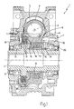
- the gear reducer 1 is designed to transmit a rotary motion between two mutually orthogonal axes 2 and 3 and comprises a worm screw 4 fitted on a shaft 5 sharing the axis 2, and a crown-wheel assembly 6 designed to rotate about the axis 3.
- the worm 4 and the crown-wheel assembly 6 are contained within a guard 7.
- the crown-wheel assembly 6 comprises a crown wheel 8 and a hub 9 (both having the same axis 3), which is separate from the crown wheel 8.
- the crown-wheel assembly 6 moreover comprises a torque limiter 10 designed to render the crown wheel 8 and the hub 9 fixed to one another during normal operation.
- the torque limiter 10 comprises a plurality of steel disks 11 fitted mechanically to the crown wheel 8, and a plurality of sintered disks 12, which are fitted mechanically to the hub 9 and each of which is set between two steel disks 11.
- Both the steel disks 11 and the sintered disks 12 have a central hole within which the hub 9 is housed.
- the fits between the steel disks 11 and the crown wheels 8, and, respectively, between the sintered disks 12 and the hub 9 are of a traditional type (with splined shaft) known in the sector of production of clutches.
- the torque limiter 10 comprises a contrast ring 14, which is set around the hub 9 and on which there rests the pack of disks 13 compressed against one another, and a thrust piston 15, which is also set around the hub 9 and which acts on the pack 13 of disks on the side opposite to the contrast ring 14. Furthermore, the torque limiter 10 comprises a plurality of helical springs 16, which are arranged with their own axis 17 parallel to the axis 3 of the hub 9 and only two of which are visible in Figure 1.
- the helical springs 16 are compressed between the thrust piston 15 and a thrust ring 18, which is set around the hub 9 and the position of which determines compression of the springs 16 themselves. In other words, the springs 16 exert a thrust on the thrust piston 15, which in turn compacts the pack 13 of disks against the contrast ring 14.
- the torque limiter 10 moreover comprises a ring nut 19, the movement of which determines the position of the thrust ring 18, and a lock washer 20 set between the thrust ring 18 and the ring nut 19 and designed to guarantee maintenance of the position of the thrust ring 18 itself as set by use of the ring nut 19.
- Both the ring nut 19 and the lock washer 20 are arranged around the hub 9.
- the ring nut 19 by means of the lock washer 20 exerts a thrust on the thrust ring 18, which in turn compresses the springs 16.
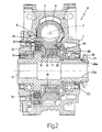
- the gear reducer 21 comprises a crown-wheel assembly 22, which in turn comprises a hub 23, an end portion of which 23a extends out of the guard 7.
- the crown-wheel assembly 22 moreover comprises a torque limiter 24 having a thrust ring 25 with a sleeve portion 26, an end portion 26a of which extends out of the guard 7 in a position corresponding to the end portion 23a of the hub 23.
- the torque limiter 24 moreover comprises: a ring nut 27, which is set around the end portion 23a of the hub 23 (and which can be screwed on a thread provided on the end portion 23a) and movement of which determines the position of the thrust ring 25; and a lock washer 28 set between the thrust ring 25 and the ring nut 27 and designed to guarantee maintenance of the position of the thrust ring 25 itself as set by use of the ring nut 27.
- the sleeve portion 26 constitutes an extension of the thrust ring 25 on the outside of the guard 7, with the possibility of regulating its position and hence compression of the springs 16 from outside.
Landscapes
- Engineering & Computer Science (AREA)
- General Engineering & Computer Science (AREA)
- Mechanical Engineering (AREA)
- Transmission Devices (AREA)
- Gear Transmission (AREA)
Priority Applications (1)
| Application Number | Priority Date | Filing Date | Title |
|---|---|---|---|
| EP05425857A EP1793143A1 (fr) | 2005-12-01 | 2005-12-01 | Assemblage d'engrenage hélicoidal/avec couronne réductrice de vitesse avec limiteur de couple |
Applications Claiming Priority (1)
| Application Number | Priority Date | Filing Date | Title |
|---|---|---|---|
| EP05425857A EP1793143A1 (fr) | 2005-12-01 | 2005-12-01 | Assemblage d'engrenage hélicoidal/avec couronne réductrice de vitesse avec limiteur de couple |
Publications (1)
| Publication Number | Publication Date |
|---|---|
| EP1793143A1 true EP1793143A1 (fr) | 2007-06-06 |
Family
ID=36190720
Family Applications (1)
| Application Number | Title | Priority Date | Filing Date |
|---|---|---|---|
| EP05425857A Withdrawn EP1793143A1 (fr) | 2005-12-01 | 2005-12-01 | Assemblage d'engrenage hélicoidal/avec couronne réductrice de vitesse avec limiteur de couple |
Country Status (1)
| Country | Link |
|---|---|
| EP (1) | EP1793143A1 (fr) |
Cited By (4)
| Publication number | Priority date | Publication date | Assignee | Title |
|---|---|---|---|---|
| ITBO20090436A1 (it) * | 2009-07-07 | 2011-01-08 | Bonfiglioli Riduttori Spa | Riduttore vite senza fine-gruppo corona combinato con un riduttore epicicloidale multistadio per la generazione di energia eolica |
| CN102996758A (zh) * | 2011-09-16 | 2013-03-27 | 发得科技工业股份有限公司 | 传动机构的背隙消除装置 |
| WO2013064151A1 (fr) | 2011-10-31 | 2013-05-10 | Vestas Wind Systems A/S | Entraînement de lacet pour un système de lacet pour une turbine éolienne |
| ITBO20120090A1 (it) * | 2012-02-27 | 2013-08-28 | Bonfiglioli Riduttori Spa | Riduttore comprendente una vite-senza-fine ed un gruppo corona attrezzato con un limitatore di coppia |
Citations (7)
| Publication number | Priority date | Publication date | Assignee | Title |
|---|---|---|---|---|
| US1427025A (en) * | 1922-01-30 | 1922-08-22 | Charles A Schlafly | Safety friction gear |
| CH227655A (de) * | 1941-07-24 | 1943-06-30 | Soehne Otto Ortlinghaus | Lamellen-Rutschkupplung. |
| US2429561A (en) * | 1943-11-19 | 1947-10-21 | Buffalo Machinery Company Inc | Precision coupling |
| US3396557A (en) * | 1966-08-19 | 1968-08-13 | Black & Decker Mfg Co | Adjustable slip clutch for rotary tools |
| JPS60157515A (ja) * | 1984-01-27 | 1985-08-17 | Kawasaki Heavy Ind Ltd | 動力伝達機構の緩衝装置 |
| JPH04300425A (ja) * | 1991-03-27 | 1992-10-23 | Jidosha Denki Kogyo Co Ltd | 摩擦クラッチ付小型モータ |
| JP2004104902A (ja) * | 2002-09-09 | 2004-04-02 | Igarashi Denki Seisakusho:Kk | 小型モータ式電動アクチュエータ |
-
2005
- 2005-12-01 EP EP05425857A patent/EP1793143A1/fr not_active Withdrawn
Patent Citations (7)
| Publication number | Priority date | Publication date | Assignee | Title |
|---|---|---|---|---|
| US1427025A (en) * | 1922-01-30 | 1922-08-22 | Charles A Schlafly | Safety friction gear |
| CH227655A (de) * | 1941-07-24 | 1943-06-30 | Soehne Otto Ortlinghaus | Lamellen-Rutschkupplung. |
| US2429561A (en) * | 1943-11-19 | 1947-10-21 | Buffalo Machinery Company Inc | Precision coupling |
| US3396557A (en) * | 1966-08-19 | 1968-08-13 | Black & Decker Mfg Co | Adjustable slip clutch for rotary tools |
| JPS60157515A (ja) * | 1984-01-27 | 1985-08-17 | Kawasaki Heavy Ind Ltd | 動力伝達機構の緩衝装置 |
| JPH04300425A (ja) * | 1991-03-27 | 1992-10-23 | Jidosha Denki Kogyo Co Ltd | 摩擦クラッチ付小型モータ |
| JP2004104902A (ja) * | 2002-09-09 | 2004-04-02 | Igarashi Denki Seisakusho:Kk | 小型モータ式電動アクチュエータ |
Non-Patent Citations (3)
| Title |
|---|
| PATENT ABSTRACTS OF JAPAN vol. 009, no. 322 (M - 440) 18 December 1985 (1985-12-18) * |
| PATENT ABSTRACTS OF JAPAN vol. 017, no. 114 (M - 1377) 9 March 1993 (1993-03-09) * |
| PATENT ABSTRACTS OF JAPAN vol. 2003, no. 12 5 December 2003 (2003-12-05) * |
Cited By (8)
| Publication number | Priority date | Publication date | Assignee | Title |
|---|---|---|---|---|
| ITBO20090436A1 (it) * | 2009-07-07 | 2011-01-08 | Bonfiglioli Riduttori Spa | Riduttore vite senza fine-gruppo corona combinato con un riduttore epicicloidale multistadio per la generazione di energia eolica |
| CN102996758A (zh) * | 2011-09-16 | 2013-03-27 | 发得科技工业股份有限公司 | 传动机构的背隙消除装置 |
| WO2013064151A1 (fr) | 2011-10-31 | 2013-05-10 | Vestas Wind Systems A/S | Entraînement de lacet pour un système de lacet pour une turbine éolienne |
| ITBO20120090A1 (it) * | 2012-02-27 | 2013-08-28 | Bonfiglioli Riduttori Spa | Riduttore comprendente una vite-senza-fine ed un gruppo corona attrezzato con un limitatore di coppia |
| WO2013128386A1 (fr) | 2012-02-27 | 2013-09-06 | Bonfiglioli Riduttori S.P.A. | Réducteur à engrenages comprenant une vis sans fin et ensemble grande couronne pourvu d'un limiteur de couple |
| CN104136804A (zh) * | 2012-02-27 | 2014-11-05 | 邦飞利减速器股份有限公司 | 包括蜗杆及设置有转矩限制器的冠状齿轮组件的齿轮减速器 |
| US9394970B2 (en) | 2012-02-27 | 2016-07-19 | Bonfiglioli Riduttori S.P.A. | Gear reducer comprising a worm and a worm gear assembly provided with a torque limiter |
| CN104136804B (zh) * | 2012-02-27 | 2018-02-13 | 邦飞利减速器股份有限公司 | 齿轮减速器 |
Similar Documents
| Publication | Publication Date | Title |
|---|---|---|
| EP2053258B1 (fr) | Gamme de dispositifs d'adapteurs et dispositif d'adapteur | |
| KR102241231B1 (ko) | 과부하 방지부를 갖는 구동 장치 | |
| US9221158B2 (en) | Power screwdriver overload prevention means | |
| US11118664B2 (en) | Limited slip differential with clutch for inhibiting speed differentiation between side gears | |
| US5741199A (en) | Limited slip differential recessed spring design | |
| EP1793143A1 (fr) | Assemblage d'engrenage hélicoidal/avec couronne réductrice de vitesse avec limiteur de couple | |
| CN101813146B (zh) | 联轴制动限载器 | |
| CN203130848U (zh) | 闭门器上的安全离合装置 | |
| CN101305209A (zh) | 有过载安全离合器的滚珠丝杠传动装置 | |
| US20150027820A1 (en) | Electromechanical brake device | |
| US3704765A (en) | Overload clutch | |
| EP1319136B1 (fr) | Ensemble de dispositifs adaptateurs et dispositif adaptateur | |
| CN113124067B (zh) | 连杆-扭簧式过载保护离合器 | |
| DE202012012654U1 (de) | Winkelschleifer | |
| CN114215860A (zh) | 一种机械式定量调节扭矩限制器 | |
| CN211117222U (zh) | 电动螺旋压力机用齿轮传动的扭矩限制保护装置 | |
| US20100206112A1 (en) | Linear actuator | |
| CN223152587U (zh) | 一种防过载传动机构 | |
| CN203413041U (zh) | 一种带双重保护的减速机输出装置 | |
| CN107246445A (zh) | 半离合式双离合器 | |
| RU2025276C1 (ru) | Механический пресс с шестернеэксцентриковым приводом | |
| GB2164103A (en) | Torque limiter coupling | |
| CN203009709U (zh) | 工程机械及其蜗轮蜗杆减速器 | |
| RU2229042C2 (ru) | Предохранительная фрикционная муфта предельного момента вращения | |
| SU1055915A1 (ru) | Предохранительна фрикционна муфта М.П.Шишкарева |
Legal Events
| Date | Code | Title | Description |
|---|---|---|---|
| PUAI | Public reference made under article 153(3) epc to a published international application that has entered the european phase |
Free format text: ORIGINAL CODE: 0009012 |
|
| AK | Designated contracting states |
Kind code of ref document: A1 Designated state(s): AT BE BG CH CY CZ DE DK EE ES FI FR GB GR HU IE IS IT LI LT LU LV MC NL PL PT RO SE SI SK TR |
|
| AX | Request for extension of the european patent |
Extension state: AL BA HR MK YU |
|
| 17P | Request for examination filed |
Effective date: 20071203 |
|
| 17Q | First examination report despatched |
Effective date: 20080114 |
|
| AKX | Designation fees paid |
Designated state(s): AT BE BG CH CY CZ DE DK EE ES FI FR GB GR HU IE IS IT LI LT LU LV MC NL PL PT RO SE SI SK TR |
|
| GRAP | Despatch of communication of intention to grant a patent |
Free format text: ORIGINAL CODE: EPIDOSNIGR1 |
|
| GRAC | Information related to communication of intention to grant a patent modified |
Free format text: ORIGINAL CODE: EPIDOSCIGR1 |
|
| STAA | Information on the status of an ep patent application or granted ep patent |
Free format text: STATUS: THE APPLICATION IS DEEMED TO BE WITHDRAWN |
|
| 18D | Application deemed to be withdrawn |
Effective date: 20110812 |