EP1793149B1 - Actionneur électromagnétique - Google Patents
Actionneur électromagnétique Download PDFInfo
- Publication number
- EP1793149B1 EP1793149B1 EP20060124873 EP06124873A EP1793149B1 EP 1793149 B1 EP1793149 B1 EP 1793149B1 EP 20060124873 EP20060124873 EP 20060124873 EP 06124873 A EP06124873 A EP 06124873A EP 1793149 B1 EP1793149 B1 EP 1793149B1
- Authority
- EP
- European Patent Office
- Prior art keywords
- valve
- armature
- magnet armature
- face
- sealing
- Prior art date
- Legal status (The legal status is an assumption and is not a legal conclusion. Google has not performed a legal analysis and makes no representation as to the accuracy of the status listed.)
- Active
Links
- 238000007789 sealing Methods 0.000 claims description 87
- 230000033001 locomotion Effects 0.000 claims description 35
- 238000013016 damping Methods 0.000 claims description 29
- 230000005540 biological transmission Effects 0.000 claims description 18
- 239000002184 metal Substances 0.000 claims description 3
- 239000004033 plastic Substances 0.000 claims description 2
- 238000000465 moulding Methods 0.000 claims 1
- 239000012530 fluid Substances 0.000 description 7
- 230000002238 attenuated effect Effects 0.000 description 3
- 238000006073 displacement reaction Methods 0.000 description 3
- 238000000034 method Methods 0.000 description 3
- 239000000203 mixture Substances 0.000 description 3
- 230000015572 biosynthetic process Effects 0.000 description 2
- 230000000694 effects Effects 0.000 description 2
- 230000010355 oscillation Effects 0.000 description 2
- 239000000126 substance Substances 0.000 description 2
- 238000002485 combustion reaction Methods 0.000 description 1
- 230000006735 deficit Effects 0.000 description 1
- 238000010586 diagram Methods 0.000 description 1
- 230000001747 exhibiting effect Effects 0.000 description 1
- 230000009969 flowable effect Effects 0.000 description 1
- 239000007789 gas Substances 0.000 description 1
- 230000005484 gravity Effects 0.000 description 1
- 238000009434 installation Methods 0.000 description 1
- 239000007788 liquid Substances 0.000 description 1
- 239000002991 molded plastic Substances 0.000 description 1
- 230000003071 parasitic effect Effects 0.000 description 1
- 230000000750 progressive effect Effects 0.000 description 1
Images
Classifications
-
- F—MECHANICAL ENGINEERING; LIGHTING; HEATING; WEAPONS; BLASTING
- F16—ENGINEERING ELEMENTS AND UNITS; GENERAL MEASURES FOR PRODUCING AND MAINTAINING EFFECTIVE FUNCTIONING OF MACHINES OR INSTALLATIONS; THERMAL INSULATION IN GENERAL
- F16K—VALVES; TAPS; COCKS; ACTUATING-FLOATS; DEVICES FOR VENTING OR AERATING
- F16K31/00—Actuating devices; Operating means; Releasing devices
- F16K31/02—Actuating devices; Operating means; Releasing devices electric; magnetic
- F16K31/06—Actuating devices; Operating means; Releasing devices electric; magnetic using a magnet, e.g. diaphragm valves, cutting off by means of a liquid
- F16K31/0686—Braking, pressure equilibration, shock absorbing
- F16K31/0689—Braking of the valve element
-
- H—ELECTRICITY
- H01—ELECTRIC ELEMENTS
- H01F—MAGNETS; INDUCTANCES; TRANSFORMERS; SELECTION OF MATERIALS FOR THEIR MAGNETIC PROPERTIES
- H01F7/00—Magnets
- H01F7/06—Electromagnets; Actuators including electromagnets
- H01F7/08—Electromagnets; Actuators including electromagnets with armatures
- H01F7/088—Electromagnets; Actuators including electromagnets with armatures provided with means for absorbing shocks
-
- H—ELECTRICITY
- H01—ELECTRIC ELEMENTS
- H01F—MAGNETS; INDUCTANCES; TRANSFORMERS; SELECTION OF MATERIALS FOR THEIR MAGNETIC PROPERTIES
- H01F7/00—Magnets
- H01F7/06—Electromagnets; Actuators including electromagnets
- H01F7/08—Electromagnets; Actuators including electromagnets with armatures
- H01F7/16—Rectilinearly-movable armatures
- H01F7/1607—Armatures entering the winding
Definitions
- the invention relates to an electromagnetic actuator with a cylindrical magnet armature, which is slidably mounted in a hollow cylindrical and closed by a bottom armature space of a coil housing of the actuator between two spaced by a stroke H end positions and in the vicinity of the bottom end position one for damping its movement Serving pressure space between the bottom on the one hand and a floor facing the first end of the magnet armature and a throttle serving as an annular gap on the other hand, wherein for forming the annular gap an inner sealing surface disposed in the magnet armature axial bore, starting from the first end side toward a second end face of the Magnet armature extends, and an inner sealing surface coaxial to the outer sealing surface are provided on a sealing body attached to the coil housing and the pressure chamber with variable height of the annular gap within a in the region of the Bottom near end position extending portion .DELTA.H of the stroke H of the armature with ⁇ H ⁇ H is formed.
- the invention also relates to an electromagnetic hydraulic valve with such an actuator.
- the Indian JP 2002272080 A proposed actuator is part of an electromagnetic control valve with a solenoid operated by the valve lifter whose movement is damped in the region of the upper, the bottom of the bobbin case near end position.
- a pressure builds up in a pressure space between the bottom and the end face of the magnet armature facing the bottom, which-apart from leaks through the guide gap of the magnet armature-can only relieve pressure via an annular gap serving as a throttle.
- This annular gap is between a continuous one Axial bore of the armature and a running in the axial bore shaft formed with the armature firmly bolted valve stem.
- An electromagnetic hydraulic valve with a damped in the end position actuator of the type mentioned is considered from the considered generic JP 58 081281 A out.
- the JP 59 188105 A shows a pneumatically damped piston in the end position.
- the invention is therefore based on the object to avoid these disadvantages and thus to provide an electromagnetic actuator, the armature is motion-damped without significant impairment of the switching dynamics of the actuator with simultaneous targeted influenceability of the switching process.
- this object is achieved in that the armature space is limited by a sleeve housing the lining forming the bottom and made of non-magnetic metal sleeve, on which the sealing body is integrally formed from the ground by deep drawing.
- the sleeve which shields the armature of unwanted electromagnetic forces are used simultaneously as a sealing body, so that the cost and installation costs for an additional, serving as a sealing member in the actuator deleted.
- the height of the annular gap which is variable via its stroke, are available as throttle parameters.
- both the course of the annular gap height and its position with respect to the respective end position largely independent degrees of freedom to optimize the course of movement of the armature.
- the Pressure chamber then depending on the direction of movement of the armature either only as over the annular gap relieving pressure chamber or only as over the annular gap nachsaugender vacuum chamber is effective.
- the position and the height of the annular gap forming the outer sealing surface on the sealing body and the inner sealing surface within the axial bore can also be chosen so that the movement damping of the armature is not effective until final reaching one of the end positions, but is canceled shortly before reaching the end position , This can be advantageous, for example, if in the end position, a rapid pressure equalization in the pressure chamber is desired.
- an electromagnetic hydraulic valve comprising the actuator and the control valve is provided with a valve housing connected to the coil housing.
- the magnet armature is in operative connection with a valve stem extending in the valve stem or is part of this valve stem, which controls the connection between terminals formed in the valve housing for hydraulic fluid.
- Such a distance or component length ratio takes into account component scatters due to unavoidable component length tolerances and ensures that the first closing body always rests completely with its sealing surface on the first sealing seat before the magnet armature reaches the end position lying near the bottom.
- the inner sealing surface of the axial bore and the outer sealing surface of the sealing body can then be positioned relative to one another in such a way that the movement damping is at least partially effective in the region of an idle stroke of the magnet armature. This idle stroke results from the difference L L - (L V + L A ).
- control valve is designed as a 3/2-way switching valve, which has an end-side pressure connection and in each case a radially extending through a lateral surface of the hollow cylindrical valve housing working port and tank connection.
- first sealing seat between the pressure connection and the working connection and a second sealing body corresponding with a second sealing seat between the working connection and the tank connection are arranged.
- the magnet armature should be tubular with a continuous axial bore and the valve tappet designed as a plastic made and axial guide ribs exhibiting molded body.
- the axial guide ribs center the valve stem radially in the valve housing and are with Axialab accountsn, which form the force transmission surface of the valve stem and pass into a floating in the axial bore of the magnet armature centering, on serving as a force transmission surface of the magnet armature second end face of the armature.
- an electromagnetic hydraulic valve comprising the actuator and the control valve is provided with a preferred combination of features explained above.
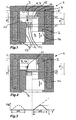
- FIG. 1 shows an electromagnetic actuator 1 with a cylindrical armature 2, which is slidably mounted in a hollow cylindrical and by a bottom 3 closed armature space 4 of a coil housing 5 of the actuator 1 between two spaced by a stroke H end positions.
- the bottom or bottom end position as shown to the left of the centerline of the actuator 1 is designated 6, while that of the bottom 3 is near or top end position as shown to the right of the center line is denoted by 7 below.
- the term fluid is to be understood as meaning all flowable substances and substance mixtures, ie liquids and gases and mixtures thereof.
- a pressure chamber 9 designed as a pressure chamber 8 is enclosed in the region of this end position 7.
- the pressure chamber 9 is bounded on the one hand by the bottom 3 and on the other hand by a first end face 10 of the magnet armature 2 facing the bottom 3 and an annular gap 11.
- the annular gap 11 is formed by an inner sealing surface 12 within an axial bore 13 extending in the magnet armature 2 and an outer sealing surface 14 coaxial with the inner sealing surface 12 on a sealing body 15 extending from the bottom 3 and secured to the coil housing 5.
- the movement damping of the armature 2 is based on the pressurization of the fluid located in the pressure chamber 9, which is displaced over the annular gap 11 by overcoming a throttle resistance in the direction of a bottom 3 remote from the second end face 16 of the armature 2.
- the inner sealing surface 12 is spaced from the outer sealing surface 14 by a damping-free lifting portion H 0 , in conjunction with a variable height H D of the annular gap 11 a tuned to the Hubkoordinate y of the armature 2 damping characteristic can be made.
- Essential parameters for this purpose in addition to the damping-free lifting section H 0, a height a of the inner sealing surface 12 and a height d of the outer sealing surface 14.
- the length of the section .DELTA.H corresponds in this case the sum of the height a of the inner sealing surface 12 and the height d of the outer sealing surface 14 and is selected that the sealing surfaces 12 and 14 no longer overlap immediately before reaching the upper end position 7 of the magnet armature 2. Consequently, the movement of the armature 2 is shortly before the upper end position 7 again without attenuation, since the pressure chamber 9 can relieve rapidly due to the then no longer present annular gap 11.
- the pressure chamber 9 of the actuator 1 according to FIG. 2 during the movement of the armature 2 in the direction of the lower end position 6 as a vacuum chamber 17 is effective. Also in this case, the movement of the armature 2 after the damping-free lifting section H 0 by formation of the annular gap 11 with the height H D , as it results for the intermediate position of the armature 2 shown dotted, attenuated. However, in this case, the movement damping is based on the negative pressure generated in the pressure chamber 9, so that fluid now comes to pressure equalization from the direction of the second end face 16 of the armature 2, overcoming the throttle resistance through the annular gap 11 in the pressure chamber 9.
- the damping characteristic can be coordinated via the design of the inner sealing surface 12 and the outer sealing surface 14.
- the for FIG. 1 and FIG. 2 described damping characteristics combine to the effect that the movement of the armature 2 is attenuated both in the upper end position 7 and in the lower end position 6. This can be achieved, for example, by the fact that the in FIG. 2 shown sealing body 15 to the outer sealing surface 14 according to FIG. 1 is extended. Consequently, the in FIG. 3 illustrated course for the height H D of the annular gap 11 to the in FIG. 3 dashed section shown .DELTA.H 'in the region of the lower end position 6 with respect FIG. 1 or the upper end position 7 with respect FIG. 2 be extended.
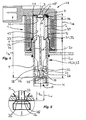
- An in FIG. 4 disclosed electromagnetic hydraulic valve 18 includes the actuator 1 and a control valve 20 designed as a seat valve 19, wherein the movement of the armature 2 based on the in FIG. 1 illustrated principle is attenuated in the upper end position 7.
- Shown is a connected to the coil housing 5 hollow cylindrical valve housing 21 in which an actuated by the armature 2 valve stem 22 controls the connection between formed in the valve housing 21 ports for hydraulic fluid.
- at these connections of the 3/2-way switching valve 23 and adapted to control hydraulically displaceable control elements of a variable valve train of an internal combustion engine suitable control valve 20 is a frontally arranged in the valve housing 21 pressure port P and each radially through a lateral surface 24 of the valve housing 21 extending working port A and tank connection T.
- first closing body 25 which is conical and corresponds with a arranged in the valve housing 21 first sealing seat 26. This serves as an axial stop for the first closing body 25, so that its stroke and, as it were, the stroke of the valve lifter 22 firmly connected to the first closing body 25 is limited in the direction of the upper end position 7 of the magnet armature 2 by the first sealing seat 26.
- the connection between the pressure ports A and T is controlled by a second closing body 27, which corresponds to a second sealing seat 28.
- the armature space 4 is bounded by a sleeve housing 5 lining and the bottom 3 forming sleeve 29 made of non-magnetic metal, which shields the slidingly mounted in the sleeve 29 armature 2 against electromagnetic interference forces.
- the outgoing of the bottom 3 sealing body 15 is integrally formed with the outer sealing surface 14 in a deep-drawing process to the sleeve 29.
- This distance or component length ratio takes into account unavoidable component length tolerances and ensures that the sealing surface 35 of the first closing body 25 always bears completely against the first sealing seat 26 before the magnet armature 2 reaches the upper end position 7 after an idle stroke.
- the idle stroke results from the difference L L - (L V + L A ) and is identical to the distance between the force transmission surface 33 of the valve stem 22 and the force transmission surface 34 of the magnet armature 2, when the sealing surface 35 of the first closing body 25 at the first sealing seat 26th and the armature 2 abut the bottom 3.
- the movement of the armature 2 and the valve stem 22 takes place from the lower end position 6 in the direction of the upper end position 7 only by the force applied to the end-side pressure port P and acting on the valve stem 22 pressing force.
- an undamped magnet armature then there would be the risk that the armature in the upper end position 7 bounces on the bottom 3 and again hits the valve tappet 22, whereby the first closing body 25 would be excited to oscillate with respect to the first sealing seat 26.
- Such oscillations can extend over a relatively long period of time and lead to the initially described disruptive effects with regard to the pressure curve in the hydraulic system to be controlled by the hydraulic valve.
- the pressure chamber 9 limiting annular gap 11 is formed by the inner sealing surface 12 of the axial bore 13 and the outer sealing surface 14 of the sealing body 15 only when the sealing surface 35 of the first closing body 25 of the valve stem 22 is already applied to the first sealing seat 26.
- the portion .DELTA.H in which the movement damping of the armature 2 is effected by partial displacement of the oil-air mixture in the pressure chamber 9 via the annular gap 11, completely within the aforementioned idle stroke L L - (L V + L A ); that is, ⁇ H ⁇ L L - (L V + L A ).
- the height H D of the annular gap 11 increases continuously during the partial section ⁇ H, so that the armature 2 is decelerated until the final end position 7 with progressive damping is finally reached.
- the armature 2 can slide back under the action of gravity to the valve tappet 22 and seat comparatively gently on the axial shoulders 31 of the axial guide ribs 30. Since the inner sealing surface 12 of the axial bore 13 and the outer sealing surface 14 of the sealing body 15 do not overlap in this position, consequently the movement damping of the magnet armature 2 is effective only outside the stroke range of the valve tappet 22. In this respect, the dynamics of the hydraulic valve 18, ie the switching time of the valve stem 22 neither during closing nor during the opening process in which the connection between the pressure port P and the working port A is closed or opened, affected and with the dynamics of a hydraulic valve with undamped magnet armature comparable.
Landscapes
- Engineering & Computer Science (AREA)
- Physics & Mathematics (AREA)
- Electromagnetism (AREA)
- General Engineering & Computer Science (AREA)
- Power Engineering (AREA)
- Mechanical Engineering (AREA)
- Magnetically Actuated Valves (AREA)
- Valve Device For Special Equipments (AREA)
- Fluid-Damping Devices (AREA)
Claims (6)
- Actionneur électromagnétique comprenant un induit magnétique cylindrique (2) d'un boîtier de bobine (5) de l'actionneur (1), lequel induit magnétique est monté dans un espace d'induit (4) cylindrique creux et fermé d'un côté par un fond (3), de manière à pouvoir coulisser entre deux positions de fin de course (6, 7) espacées d'une course H, et qui, dans la région de la position de fin de course (7) proche du fond (3), contient un espace de pression (9) servant à amortir son mouvement, entre le fond (3) d'une part et un premier côté frontal (10) de l'induit magnétique (2) tourné vers le fond (3), et une fente annulaire (11) servant d'étranglement d'autre part, une surface d'étanchéité interne (12) étant prévue pour former la fente annulaire (11) à l'intérieur d'un alésage axial (13) disposé dans l'induit magnétique (2), lequel s'étend depuis le premier côté frontal (10) dans la direction d'un deuxième côté frontal (16) de l'induit magnétique (2), et une surface d'étanchéité externe (14) coaxiale à la surface d'étanchéité interne (12) étant prévue sur un corps d'étanchéité (15) fixé au boîtier de bobine (5), et l'espace de pression (9) étant formé en cas de variation de hauteur (HD) de la fente annulaire (11) à l'intérieur d'une portion partielle ΔH de la course H de l'induit magnétique (2) s'étendant dans la région de la position de fin de course (7) proche du fond (3), avec ΔH < H, caractérisé en ce que l'espace d'induit (4) est limité par un manchon (29) doublant le boîtier de bobine (5), formant le fond (3) et constitué d'un métal non magnétique, sur lequel est formé d'une seule pièce par emboutissage profond le corps d'étanchéité (15) à partir du fond (3).
- Soupape hydraulique électromagnétique comprenant une soupape de commande (20) et un actionneur (1) selon la revendication 1, caractérisée en ce que la soupape hydraulique (18) présente un boîtier de soupape (21) connecté au boîtier de bobine (5), l'induit magnétique (2) étant en liaison fonctionnelle avec un poussoir de soupape (22) s'étendant dans le boîtier de soupape (21) ou faisant partie du poussoir de soupape (22), qui commande la connexion entre les raccords de fluide hydraulique réalisés dans le boîtier de soupape (21).
- Soupape hydraulique selon la revendication 2, caractérisée en ce que- la soupape de commande (20) est réalisée sous forme de soupape à siège (19) avec au moins un premier siège d'étanchéité (26) disposé dans le boîtier de soupape (21) ;- le poussoir de soupape (22) est en liaison fonctionnelle avec au moins un premier corps de fermeture (25) qui correspond avec le premier siège d'étanchéité (26) de telle sorte que le premier siège d'étanchéité (26) serve de butée axiale limitant la course du premier corps de fermeture (25) dans la direction de la position de fin de course (7) proche du fond (3) de l'induit magnétique (2) ;- l'induit magnétique (2) et le poussoir de soupape (22) sont en liaison de pression libre dans la direction de la force de traction par le biais de surfaces de transfert de force (33, 34) tournées l'une vers l'autre, où, pour une distance LV, une distance LA et une distance LL, on a : LL > (LV + LA), si- LV est la distance entre une surface d'étanchéité (35) s'appliquant contre le premier siège d'étanchéité (26) du premier corps de fermeture (25) et la surface de transfert de force (33) du poussoir de soupape (22) ;- LA est la distance entre la surface de transfert de force (34) de l'induit magnétique (2) et le premier côté frontal (10) de l'induit magnétique (2) et- LL est la distance entre le premier siège d'étanchéité (26) et le fond (3).
- Soupape hydraulique selon la revendication 3, caractérisée en ce que la portion partielle ΔH est directement adjacente à la position de fin de course (7) proche du fond (3) de l'induit magnétique (2), et l'on a : ΔH ≤ LL - (LV + LA).
- Soupape hydraulique selon la revendication 3, caractérisée en ce que- la soupape de commande (20) est réalisée sous forme de soupape à 3/2 voies (23), qui présente un raccord de pression côté frontal (P) et à chaque fois un raccord de travail (A) et un raccord de réservoir (T) s'étendant radialement à travers une surface d'enveloppe (24) du boîtier de soupape cylindrique creux (21) ;- le premier siège d'étanchéité (26) est disposé entre le raccord de pression (P) et le raccord de travail (A) et un deuxième siège d'étanchéité (28) correspondant avec un deuxième corps de fermeture (27) est disposé entre le raccord de travail (A) et le raccord de réservoir (T).
- Soupape hydraulique selon la revendication 3, caractérisée en ce que l'induit magnétique (2) est réalisé sous forme tubulaire avec un alésage axial traversant (13) et le poussoir de soupape (22) est réalisé sous forme de corps moulé fabriqué en plastique et présentant des nervures de guidage axiales (30), lesquelles nervures de guidage axiales (30) centrent radialement le poussoir de soupape (22) dans le boîtier de soupape (21) et s'appliquent, avec des épaulements axiaux (31), qui forment la surface de transfert de force (33) du poussoir de soupape (22) et qui se prolongent dans un tourillon de centrage (32) monté flottant dans l'alésage axial (13) de l'induit magnétique (2), sur le deuxième côté frontal (16) de l'induit magnétique (2) servant de surface de transfert de force (34) de l'induit magnétique (2).
Applications Claiming Priority (1)
| Application Number | Priority Date | Filing Date | Title |
|---|---|---|---|
| DE200510057296 DE102005057296A1 (de) | 2005-12-01 | 2005-12-01 | Elektromagnetischer Aktuator |
Publications (3)
| Publication Number | Publication Date |
|---|---|
| EP1793149A2 EP1793149A2 (fr) | 2007-06-06 |
| EP1793149A3 EP1793149A3 (fr) | 2009-12-02 |
| EP1793149B1 true EP1793149B1 (fr) | 2011-06-29 |
Family
ID=37864281
Family Applications (1)
| Application Number | Title | Priority Date | Filing Date |
|---|---|---|---|
| EP20060124873 Active EP1793149B1 (fr) | 2005-12-01 | 2006-11-28 | Actionneur électromagnétique |
Country Status (3)
| Country | Link |
|---|---|
| EP (1) | EP1793149B1 (fr) |
| CN (1) | CN101039060A (fr) |
| DE (1) | DE102005057296A1 (fr) |
Families Citing this family (2)
| Publication number | Priority date | Publication date | Assignee | Title |
|---|---|---|---|---|
| DE102008029434A1 (de) | 2008-06-20 | 2009-12-24 | Schaeffler Kg | Elektromagnetischer Aktuator |
| ES2373346T3 (es) | 2008-12-15 | 2012-02-02 | Kendrion Binder Magnete Gmbh | Electroimán con disco de amortiguación. |
Family Cites Families (4)
| Publication number | Priority date | Publication date | Assignee | Title |
|---|---|---|---|---|
| JPS5881281A (ja) | 1981-11-06 | 1983-05-16 | Ckd Controls Ltd | ガス用電磁弁 |
| JPS59188105A (ja) | 1983-04-08 | 1984-10-25 | Matsushita Electric Ind Co Ltd | ソレノイド |
| JP3753003B2 (ja) | 2001-03-06 | 2006-03-08 | 株式会社デンソー | シャフト付きソレノイド型アクチュエータ |
| DE10359363A1 (de) * | 2003-12-18 | 2005-07-14 | Ina-Schaeffler Kg | Elektromagnetisches Hydraulikventil, inbesondere 3/2-Wegeschaltventil zur Steuerung eines variablen Ventiltriebes einer Brennkraftmaschine |
-
2005
- 2005-12-01 DE DE200510057296 patent/DE102005057296A1/de not_active Withdrawn
-
2006
- 2006-11-28 EP EP20060124873 patent/EP1793149B1/fr active Active
- 2006-12-01 CN CNA2006101636518A patent/CN101039060A/zh active Pending
Also Published As
| Publication number | Publication date |
|---|---|
| CN101039060A (zh) | 2007-09-19 |
| EP1793149A2 (fr) | 2007-06-06 |
| DE102005057296A1 (de) | 2007-06-06 |
| EP1793149A3 (fr) | 2009-12-02 |
Similar Documents
| Publication | Publication Date | Title |
|---|---|---|
| DE102009016464B3 (de) | Verstellbare Dämpfventileinrichtung | |
| EP0400395B1 (fr) | Amortisseur de choc | |
| DE19680572C1 (de) | Stufenventil | |
| EP1004066A1 (fr) | Soupape hydraulique electromagnetique | |
| DE4212550C2 (de) | Ventilanordnung mit einem Wegeventil | |
| DE4237681A1 (en) | Electromagnetically operable double-seat valve for vehicle automatic transmission | |
| EP1668283B1 (fr) | Vanne magnetique comprenant un disque amortisseur reducteur de bruit | |
| DE102015109474A1 (de) | Umschaltventil und Pleuel mit einem Umschaltventil | |
| DE102016008306A1 (de) | Pleuel mit verstellbarer Pleuellänge | |
| EP1621793A1 (fr) | Ressort à gaz | |
| DE102010060264B4 (de) | Elektromagnetisches Stellglied | |
| DE10143959A1 (de) | Hydraulisch gesteuerter Aktuator zur Betätigung eines Ventils | |
| EP0918678A1 (fr) | Dispositif de commande electrohydraulique | |
| EP2519732B1 (fr) | Vanne de controle du debit de commande electrique, destinee en particulier a commander le debit d'une pompe haute pression a carburant | |
| DE2949202C2 (fr) | ||
| EP1793149B1 (fr) | Actionneur électromagnétique | |
| EP0976948B1 (fr) | Dispositif d'amortissement de masses déplacées, en particulier pour systèmes moteurs électromagnétiques | |
| DE102011055688B4 (de) | Arretierbares Kolben-Zylinder-Aggregat | |
| EP4396487B1 (fr) | Électrovanne et système de réservoir d'hydrogène comprenant une électrovanne | |
| WO2016026690A1 (fr) | Électrovanne | |
| DE102006001924A1 (de) | Hydraulikventil | |
| DE102008029434A1 (de) | Elektromagnetischer Aktuator | |
| EP3390807B1 (fr) | Soupape dans une pompe haute pression d'un système d'injection de carburant | |
| DE102024202482B3 (de) | Verstellbare Dämpfventileinrichtung für einen Schwingungsdämpfer | |
| DE10302385B4 (de) | Hydraulisch dämpfendes Lager |
Legal Events
| Date | Code | Title | Description |
|---|---|---|---|
| PUAI | Public reference made under article 153(3) epc to a published international application that has entered the european phase |
Free format text: ORIGINAL CODE: 0009012 |
|
| AK | Designated contracting states |
Kind code of ref document: A2 Designated state(s): AT BE BG CH CY CZ DE DK EE ES FI FR GB GR HU IE IS IT LI LT LU LV MC NL PL PT RO SE SI SK TR |
|
| AX | Request for extension of the european patent |
Extension state: AL BA HR MK YU |
|
| 17P | Request for examination filed |
Effective date: 20070823 |
|
| PUAL | Search report despatched |
Free format text: ORIGINAL CODE: 0009013 |
|
| AK | Designated contracting states |
Kind code of ref document: A3 Designated state(s): AT BE BG CH CY CZ DE DK EE ES FI FR GB GR HU IE IS IT LI LT LU LV MC NL PL PT RO SE SI SK TR |
|
| AX | Request for extension of the european patent |
Extension state: AL BA HR MK RS |
|
| 17Q | First examination report despatched |
Effective date: 20100222 |
|
| AKX | Designation fees paid |
Designated state(s): DE ES FR GB IT SE |
|
| GRAP | Despatch of communication of intention to grant a patent |
Free format text: ORIGINAL CODE: EPIDOSNIGR1 |
|
| GRAS | Grant fee paid |
Free format text: ORIGINAL CODE: EPIDOSNIGR3 |
|
| GRAA | (expected) grant |
Free format text: ORIGINAL CODE: 0009210 |
|
| RAP1 | Party data changed (applicant data changed or rights of an application transferred) |
Owner name: SCHAEFFLER TECHNOLOGIES GMBH & CO. KG |
|
| AK | Designated contracting states |
Kind code of ref document: B1 Designated state(s): DE ES FR GB IT SE |
|
| REG | Reference to a national code |
Ref country code: GB Ref legal event code: FG4D Free format text: NOT ENGLISH |
|
| REG | Reference to a national code |
Ref country code: DE Ref legal event code: R096 Ref document number: 502006009749 Country of ref document: DE Effective date: 20110825 |
|
| PG25 | Lapsed in a contracting state [announced via postgrant information from national office to epo] |
Ref country code: SE Free format text: LAPSE BECAUSE OF FAILURE TO SUBMIT A TRANSLATION OF THE DESCRIPTION OR TO PAY THE FEE WITHIN THE PRESCRIBED TIME-LIMIT Effective date: 20110629 |
|
| PGFP | Annual fee paid to national office [announced via postgrant information from national office to epo] |
Ref country code: FR Payment date: 20111214 Year of fee payment: 6 |
|
| RAP2 | Party data changed (patent owner data changed or rights of a patent transferred) |
Owner name: SCHAEFFLER TECHNOLOGIES AG & CO. KG |
|
| PLBE | No opposition filed within time limit |
Free format text: ORIGINAL CODE: 0009261 |
|
| STAA | Information on the status of an ep patent application or granted ep patent |
Free format text: STATUS: NO OPPOSITION FILED WITHIN TIME LIMIT |
|
| 26N | No opposition filed |
Effective date: 20120330 |
|
| REG | Reference to a national code |
Ref country code: DE Ref legal event code: R097 Ref document number: 502006009749 Country of ref document: DE Effective date: 20120330 |
|
| REG | Reference to a national code |
Ref country code: DE Ref legal event code: R081 Ref document number: 502006009749 Country of ref document: DE Owner name: SCHAEFFLER TECHNOLOGIES AG & CO. KG, DE Free format text: FORMER OWNER: SCHAEFFLER TECHNOLOGIES GMBH & CO. KG, 91074 HERZOGENAURACH, DE Effective date: 20120828 Ref country code: DE Ref legal event code: R081 Ref document number: 502006009749 Country of ref document: DE Owner name: SCHAEFFLER TECHNOLOGIES GMBH & CO. KG, DE Free format text: FORMER OWNER: SCHAEFFLER TECHNOLOGIES GMBH & CO. KG, 91074 HERZOGENAURACH, DE Effective date: 20120828 Ref country code: DE Ref legal event code: R081 Ref document number: 502006009749 Country of ref document: DE Owner name: SCHAEFFLER TECHNOLOGIES GMBH & CO. KG, DE Free format text: FORMER OWNER: SCHAEFFLER KG, 91074 HERZOGENAURACH, DE Effective date: 20110630 Ref country code: DE Ref legal event code: R081 Ref document number: 502006009749 Country of ref document: DE Owner name: SCHAEFFLER TECHNOLOGIES AG & CO. KG, DE Free format text: FORMER OWNER: SCHAEFFLER KG, 91074 HERZOGENAURACH, DE Effective date: 20110630 |
|
| PG25 | Lapsed in a contracting state [announced via postgrant information from national office to epo] |
Ref country code: ES Free format text: LAPSE BECAUSE OF FAILURE TO SUBMIT A TRANSLATION OF THE DESCRIPTION OR TO PAY THE FEE WITHIN THE PRESCRIBED TIME-LIMIT Effective date: 20111010 |
|
| GBPC | Gb: european patent ceased through non-payment of renewal fee |
Effective date: 20121128 |
|
| REG | Reference to a national code |
Ref country code: FR Ref legal event code: ST Effective date: 20130731 |
|
| PG25 | Lapsed in a contracting state [announced via postgrant information from national office to epo] |
Ref country code: IT Free format text: LAPSE BECAUSE OF NON-PAYMENT OF DUE FEES Effective date: 20121128 |
|
| PG25 | Lapsed in a contracting state [announced via postgrant information from national office to epo] |
Ref country code: GB Free format text: LAPSE BECAUSE OF NON-PAYMENT OF DUE FEES Effective date: 20121128 Ref country code: FR Free format text: LAPSE BECAUSE OF NON-PAYMENT OF DUE FEES Effective date: 20121130 |
|
| REG | Reference to a national code |
Ref country code: DE Ref legal event code: R081 Ref document number: 502006009749 Country of ref document: DE Owner name: SCHAEFFLER TECHNOLOGIES GMBH & CO. KG, DE Free format text: FORMER OWNER: SCHAEFFLER TECHNOLOGIES AG & CO. KG, 91074 HERZOGENAURACH, DE Effective date: 20140213 Ref country code: DE Ref legal event code: R081 Ref document number: 502006009749 Country of ref document: DE Owner name: SCHAEFFLER TECHNOLOGIES AG & CO. KG, DE Free format text: FORMER OWNER: SCHAEFFLER TECHNOLOGIES AG & CO. KG, 91074 HERZOGENAURACH, DE Effective date: 20140213 |
|
| REG | Reference to a national code |
Ref country code: DE Ref legal event code: R081 Ref document number: 502006009749 Country of ref document: DE Owner name: SCHAEFFLER TECHNOLOGIES AG & CO. KG, DE Free format text: FORMER OWNER: SCHAEFFLER TECHNOLOGIES GMBH & CO. KG, 91074 HERZOGENAURACH, DE Effective date: 20150213 |
|
| P01 | Opt-out of the competence of the unified patent court (upc) registered |
Effective date: 20230522 |
|
| PGFP | Annual fee paid to national office [announced via postgrant information from national office to epo] |
Ref country code: DE Payment date: 20250121 Year of fee payment: 19 |