EP1793352A2 - Système de surveillance et dispositif mobile d'alarme - Google Patents
Système de surveillance et dispositif mobile d'alarme Download PDFInfo
- Publication number
- EP1793352A2 EP1793352A2 EP06124184A EP06124184A EP1793352A2 EP 1793352 A2 EP1793352 A2 EP 1793352A2 EP 06124184 A EP06124184 A EP 06124184A EP 06124184 A EP06124184 A EP 06124184A EP 1793352 A2 EP1793352 A2 EP 1793352A2
- Authority
- EP
- European Patent Office
- Prior art keywords
- alarm device
- identification mark
- interface
- mobile
- communication
- Prior art date
- Legal status (The legal status is an assumption and is not a legal conclusion. Google has not performed a legal analysis and makes no representation as to the accuracy of the status listed.)
- Granted
Links
Images
Classifications
-
- G—PHYSICS
- G08—SIGNALLING
- G08B—SIGNALLING SYSTEMS, e.g. PERSONAL CALLING SYSTEMS; ORDER TELEGRAPHS; ALARM SYSTEMS
- G08B13/00—Burglar, theft or intruder alarms
- G08B13/02—Mechanical actuation
- G08B13/14—Mechanical actuation by lifting or attempted removal of hand-portable articles
- G08B13/1427—Mechanical actuation by lifting or attempted removal of hand-portable articles with transmitter-receiver for distance detection
-
- G—PHYSICS
- G08—SIGNALLING
- G08B—SIGNALLING SYSTEMS, e.g. PERSONAL CALLING SYSTEMS; ORDER TELEGRAPHS; ALARM SYSTEMS
- G08B13/00—Burglar, theft or intruder alarms
- G08B13/22—Electrical actuation
- G08B13/24—Electrical actuation by interference with electromagnetic field distribution
- G08B13/2402—Electronic Article Surveillance [EAS], i.e. systems using tags for detecting removal of a tagged item from a secure area, e.g. tags for detecting shoplifting
- G08B13/2405—Electronic Article Surveillance [EAS], i.e. systems using tags for detecting removal of a tagged item from a secure area, e.g. tags for detecting shoplifting characterised by the tag technology used
- G08B13/2414—Electronic Article Surveillance [EAS], i.e. systems using tags for detecting removal of a tagged item from a secure area, e.g. tags for detecting shoplifting characterised by the tag technology used using inductive tags
- G08B13/2417—Electronic Article Surveillance [EAS], i.e. systems using tags for detecting removal of a tagged item from a secure area, e.g. tags for detecting shoplifting characterised by the tag technology used using inductive tags having a radio frequency identification chip
-
- G—PHYSICS
- G08—SIGNALLING
- G08B—SIGNALLING SYSTEMS, e.g. PERSONAL CALLING SYSTEMS; ORDER TELEGRAPHS; ALARM SYSTEMS
- G08B21/00—Alarms responsive to a single specified undesired or abnormal condition and not otherwise provided for
- G08B21/02—Alarms for ensuring the safety of persons
- G08B21/0202—Child monitoring systems using a transmitter-receiver system carried by the parent and the child
- G08B21/0219—Circuit arrangements
-
- G—PHYSICS
- G08—SIGNALLING
- G08B—SIGNALLING SYSTEMS, e.g. PERSONAL CALLING SYSTEMS; ORDER TELEGRAPHS; ALARM SYSTEMS
- G08B21/00—Alarms responsive to a single specified undesired or abnormal condition and not otherwise provided for
- G08B21/02—Alarms for ensuring the safety of persons
- G08B21/0202—Child monitoring systems using a transmitter-receiver system carried by the parent and the child
- G08B21/0275—Electronic Article Surveillance [EAS] tag technology used for parent or child unit, e.g. same transmission technology, magnetic tag, RF tag, RFID
Definitions
- the invention relates to a mobile alarm device and a monitoring system with at least one mobile alarm device.
- Mobile alarm devices are used, for example, in areas with high potential risks for employees, ie in the security monitoring of buildings and prisons, in psychiatry or in chemical and petrochemical plants, power plants, shipyards, industrial complexes, etc.
- the mobile alarm devices usually have an alarm button or the like, the manual operation of which triggers the transmission of an alarm signal to a security center.
- Examples of such mobile alarm devices are the personal emergency signal devices LBB 6065, 6066, 6031, 6033 or 6035 from Bosch Security Systems.
- the devices mentioned optionally include a so-called tear-off alarm.
- the tear-off alarm is an automatic alarm call and is generated as soon as a plug, which is connected, for example, to a keeper for the mobile alarm device, is pulled out of a socket of the mobile alarm device. If e.g. a detainee in a correctional facility tries to seize the mobile alarm device of a warden, is pulled out of the socket by the holding strap of the plug and automatically generates an alarm.
- a portable alarm system is known.
- a purse has a first portable device with a first communication module and a mobile phone has a second portable device with a second Communication module includes.
- an SMS or similar message is sent via the public mobile network to a receiver. For example, this message is transmitted to a bank to lock a credit card.
- the inventive mobile alarm device with the features of claim 1 is formed in contrast to the known from the prior art alarm system for operation in a local monitoring system. While the known alarm system relies on public mobile telephone networks, the inventive mobile alarm device uses a local, so locally limited, private radio network. Preferably, the radio network is limited to a building or a building complex. Especially in the technical field of safety-related applications, e.g. In personal security applications, it seems unacceptable to transmit alarms over a public mobile telephone network whose availability is difficult to control. For example, short-term maintenance or network congestion of the public mobile telephone network could lead to a loss of the alarm signal.
- the mobile alarm device has a first interface, which is designed for wireless communication with an identification mark.
- the wireless communication is preferably via electromagnetic waves, in particular radio transmission, or optical transmission, e.g. Infrared, or via ultrasound, or is designed as a capacitive or inductive distance measurement.
- the identification mark on a third interface for communication with the mobile alarm device.
- This design makes it possible to replace the tethering tear-off alarm known from the prior art by a tape-free tearing alarm or a virtual tearing-off tape.
- the real retaining strap can inadvertently get caught in a disruptive contour, such as a chair, a door knob or the like, and so far an alarm has often been triggered inadvertently.
- This source of potential False alarms are eliminated by the concept of the virtual tether.
- Another advantage is the fact that the virtual tether is invisible, since the required identification mark can be hidden, for example in a trouser pocket, worn.
- the mobile alarm device has a second interface adapted for wireless communication with a communication server, the communication server comprising a fourth interface for wireless communication with the mobile alarm device.
- the communication server is realized as a personal computer with a plug-in card designed as a fourth interface.
- An alarm generator in the mobile alarm device is programmatically and / or circuitry designed to evaluate the communication signals of the first interface, so the communication signals between mobile alarm device and identification mark, and to check whether the distance between the mobile alarm device and the identification mark has exceeded a defined distance .
- the alarm generator is configured so that an alarm signal is sent via the second interface to the communication server, as soon as the evaluation and verification shows that the distance has exceeded a defined limit.
- the defined limit value can be set, for example, manually at the mobile alarm device, permanently programmed and / or transmitted from the communication server to the mobile alarm device. For example, an audible or silent alarm is triggered in response to the alarm signal.
- a short acoustic pre-alarm and / or vibration alarm is triggered at the alarm device, so that the user has the opportunity to report a false alarm.
- the user alternatively or additionally has the possibility to reduce the distance between the mobile alarm device and the identification mark below the defined limit again and to prevent an alarm. In the event that the distance is not reduced accordingly, the alarm is triggered.
- an acoustic Monitoring via the alarm device are initiated to assess the current situation based on the acoustic information.
- the communication of the mobile alarm device with the communication server according to the invention is carried out within a local monitoring system, ie a monitoring system, which is set up exclusively or almost exclusively for the communication with a plurality of mobile alarm devices.
- the defined distance is less than 3 m, preferably less than 1.5 m. This radius allows the user to carry the mobile alarm device on the body and in the hand, for example, to make settings on the alarm device without an alarm is triggered.
- the communication of the mobile alarm device with the communication server takes place in a local radio network of the local monitoring system.
- the radio network operates in the UHF or VHF range, preferably at frequencies reserved for "talkback" in pager or land-to-talk radio, or reserved for industrial, scientific and medical applications, e.g. 13.56 MHz, 27 MHz, 433 MHz, 868 MHz, 2.4 GHz. In particular, frequencies in the frequency range of 420 to 470 MHz or 146 to 174 MHz.
- the first interface is preferably designed for bidirectional communication, in particular as a transceiver, ie as a transmitter and receiver combination.
- the identification mark is equipped with a transceiver as a third interface.
- This embodiment allows the distance or presence monitoring of the identification mark by the mobile alarm device to be realized by a sequence of a request of the alarm device and an answer of the identification mark.
- a time-synchronized message protocol is used between the identification tag and the mobile alarm device, this embodiment enabling power-saving operation.
- a simplified embodiment provides that the identification mark only a transmitter (transmit-only), ie a transmitter, and the first interface as a receiver (receive-only), ie as a receiver, is formed, for monitoring the identification mark regularly, for Example every few seconds, sends out an identity signal, which is monitored by the alarm device.
- a monitoring system with at least one of the previously described alarm device and at least one identification tag and / or a communication server.
- the identification mark with the third interface is exemplified as a key ring or pendant.
- the identification mark in this embodiment is conveniently stored in a pocket, for example in a trouser pocket.
- the identification tag may be mechanically coupled to a keychain or item of protection so that an alarm is also sounded when the mobile alerting device remains on the carrier, but the keychain or item to be protected is spaced greater than the defined distance from the mobile alerting device occupies.
- the communication server is equipped with a fourth interface, preferably designed as a personal computer, and is circuit-technically and / or program-technically designed for communication with the mobile alarm device.
- the communication between the second and fourth interfaces comprises a data communication for the transmission of the alarm.
- the communication is bidirectional, so that signals from the communication server to the mobile alarm device can be transmitted.
- the communication also includes a transmission of voice information or text messages.
- the loading and / or storage station is designed for receiving the mobile alarm device and / or the identification mark and serves in particular for charging the integrated accumulators.
- a regulated storage of the identification marks in the charging station is avoided that the user take the identification mark home and forget or lose there.
- an identification mark is assigned to exactly one mobile alarm device, so that the Alarm device evaluates and / or monitors only the communication signals with this associated identification mark.
- Such an assignment is implemented in particular by the assignment of addresses or identities (ID) to the identification mark and alarm device, wherein preferably both are assigned the same address.
- the charging station are formed together with the mobile alarm device and / or the identification mark programmatically and / or circuitry, so that when placed in the charging station, the alarm device and / or the identification mark is switched to an idle state.
- the idle state is triggered in particular by a rest command, which is transmitted from the charging station to the alarm device and / or the identification mark.
- no requests are sent to the identification mark and / or receive no replies from the identification mark.
- the idle state of the identification mark is preferably characterized in that a power-saving mode is turned on, from which the identification mark automatically wakes up after longer intervals at periodic intervals to receive wake-up commands from the alarm device and / or the charging station, or from the identification mark by pressing one the identification mark arranged wake-up button is awakened.
- a wake-up button can also be associated with other functions and e.g. be designed as an alarm button for a hidden alarm or as a programming button.
- the mobile alarm device is designed to recognize a plurality of identification marks and to transmit information about recognized identification marks to the communication server, preferably in real time, or to store them for later transmission.
- the alarm device is designed for selective recognition, that is to say for distinguishing, the identification marks.
- Identification marks can be arranged stationarily in a building to be monitored, which emit continuously or intermittently transmission signals with their identity. For example, in a hospital, identification tags may be placed behind each door or in each patient room. As soon as an alarm device comes close to a sending identification mark, ie within the defined distance, the identity of the identification mark becomes transmitted via the alarm device to the communication server.
- the communication server determines the current position of the alarm device based on the identity of the identification mark and the sending alarm device via stored records in a database. In this way, for example, the guard of a guard or the entry of a nurse can be monitored in a hospital room. In response to the detected position of the alarm device, for example, the nurse call of a patient can be automatically deactivated. Alternatively, the device can be used if there is a cost accounting for each care act on a patient or a person in need of care, with the device automatically recording the care expenses to be billed. On the other hand, an emergency call can be automatically issued by the communication server if alarm messages are missing in the wake, or if the nurse has not arrived in the patient's room after a defined time after the nurse call is triggered.
- the identification mark is designed to communicate with a plurality of alarm devices and / or other functional modules.
- This design allows, for example, that the identification mark communicates with a door opener, so that a door is automatically actuated when the identification mark transmitted to the door opener own identity and the identity for opening and / or closing the door, for example, authorized by the communication server .
- Another option is a "door guard" to monitor if in need of assistance, e.g. People with dementia who are equipped with an identification tag, leave the home environment through a secure door. The same facility could also be used to monitor an open sentence. In both cases, as soon as an identification tag holder attempts to traverse a secure entry or exit, an alarm could be automatically triggered.
- the identification tag comprises a transmitter and / or transceiver as a third interface and preferably a control device.
- the control device is designed in particular as a microcontroller and comprises a preferably non-volatile memory in which the address and / or identity (ID) of the identification mark is stored.
- the programming of the identity is preferably done by transmitting the identity of the mobile Alarm device and / or from the communication server and / or from the charging station and / or is initiated by pressing the programming button on the identification mark.
- the programming of the identity can have a permanent or a temporally limited validity, so that, for example, "day passes” can be generated, ie identification marks whose identity is valid for one day.
- "replacement passports” can also be generated, for example temporary passports for employees who have forgotten their own identification mark.
- the daily or replacement passports are temporarily registered in the mobile alarm devices, wherein after a defined period, the registration expires, or the identity of the identification marks are automatically deleted when stored in the charging station. It is preferably provided that the mobile alarm devices automatically change from the temporary registration of a daily or replacement passport to the registration of the original identification mark.
- certain addresses or address ranges can be reserved.
- the third interface of the identification mark is designed as a transmitter or transceiver and preferably operates in a frequency range of about 40 kHz, for example in the range of 30 to 60 kHz or in a license-free RFID and / or ISM frequency band in the range of 13, 56 MHz or Range around 100 kHz ..
- an inductive transmission preferably using a ferrite antenna is used.
- the identification mark is formed as a passive unit which receives the energy for the transmission of signals and / or the energy for modulation of the emitted by the alarm device transmission field by induction from the transmission field of the alarm device.
- the alarm device has a slave control device and a master control device, wherein the slave control device is coupled to the first interface in terms of programming and / or circuitry.
- This training allows a special power-saving operation by the evaluation of the communication signals of the first interface and the distance detection is formed autonomously in the slave control device.
- the master control device is first informed and / or awakened from a particular energy-saving idle state as soon as the slave control device has registered that the distance between the mobile alarm device and the identification mark has exceeded a defined distance.
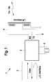
- FIG. 1 shows, in a schematic block diagram, a first exemplary embodiment of an identification mark 1 for use in a surveillance installation, e.g. for prisons, psychiatric institutions, security guards, isolated workers, public / private service workers or public transport operators, social workers, bailiffs, debt collection agencies, teachers, nurses, etc.
- a surveillance installation e.g. for prisons, psychiatric institutions, security guards, isolated workers, public / private service workers or public transport operators, social workers, bailiffs, debt collection agencies, teachers, nurses, etc.
- the identification mark 1 comprises a transmitting and receiving chip (transceiver) 2, which is connected via an interface 3 to a microcontroller (not shown).
- the interface 3 comprises a control line ⁇ C interface and a bidirectional data line DATA.
- the transmitting and receiving chip 2 is connected to a power source 4, which is designed as a rechargeable or non-rechargeable battery.
- the transmitting and receiving chip 2 is connected to a receiving antenna 5 and to a transmitting antenna 6, which are designed, for example, as a coil wound around a ferrite rod.
- the identification mark 1 comprises a button (not shown) serving as an alarm button for Triggering of an alarm and / or is designed as a programming button for initializing a programming of the microcontroller.
- the sending and receiving chip 2 may be preceded by a further receiving chip, which has a very low energy consumption (eg Austriamicrosystems AS 3931 with a power consumption of less than 10 ⁇ A), which activates the transmitting and receiving chip 2 otherwise in the energy-saving quiescent mode as soon as possible eg a request is made from the alarm device.
- a very low energy consumption eg Austriamicrosystems AS 3931 with a power consumption of less than 10 ⁇ A
- a further alternative for the transmitting and receiving chip 2 is the use of components that use the IEEE 802.15.4 / Zigbee standard and operate in the range of 868 MHz or 2.4 GHz or the NFC (Near Field Communications) standard in the range of 13, 56 MHz use.
- transponders, transmitters or receivers of the identification mark and / or the alarm device are: Bluetooth, WiFi, WLAN, HiperLAN / 2, WPAN, HomeRF, RFID, LibertyLink (Aura), nanoID / Nanonet.
- Bluetooth Wireless Fidelity
- WLAN Wireless Fidelity
- WLAN Wireless Fidelity
- WLAN Wireless Fidelity
- WLAN Wireless Fidelity
- WLAN Wireless Fidelity
- WLAN Wireless Fidelity
- HiperLAN / 2 Wireless Fidelity
- WPAN Wireless Fidelity
- HomeRF Wireless Fidelity
- RFID Wireless Fidelity
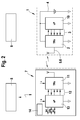
- FIG. 2 shows a block diagram of an exemplary embodiment of a surveillance system comprising an identification tag 1, a mobile alarm device 7, a communication server 8 and a loading and / or storage station 9.
- the identification mark 1 could be formed analogously to the identification mark 1 in FIG. 1, but is somewhat modified in FIG. 2.
- the identification mark 1 comprises a transceiver 2 with a combined transmitting and receiving antenna 5/6, wherein the transceiver 2 is connected via an interface 3 to a microcontroller 10. Both transceiver 2 and microcontroller 10 are powered by a battery 4.
- the mobile alarm device 7 is configured as a two-way pager wireless communication device for communication over the wireless interface 14 with the communication server 8 and includes a main microcontroller (not shown) for control.
- the mobile alarm device 7 has a transceiver 11 which is designed as a first interface for communication with the identification mark 1, in particular with the transceiver 2.
- the transceiver 11 is designed analogously to the transceiver 2.
- the transceiver 11 is connected via an interface 12 to a microcontroller 13.
- the microcontroller 13 is designed as a slave relative to the main microcontroller (master), not shown, of the alarm device 7.
- the loading and / or storage station 9 comprises receptacles for a multiplicity of identification marks 1 and alarm devices 7.
- the mobile alarm device 7 sends via the transceiver 11 and 2 a request to the identification mark 1, which answers this request by a response.
- Either request or response includes information about the identity ID of the identification tag 1, so that it is ensured that only one of the identification device 1 associated with the alarm device 7 can send a valid response.
- the distance between identification mark 1 and alarm device 7 is determined and checked whether the determined distance has exceeded a limit for a maximum distance. Alternatively, the presence or absence of the identification mark 1 is detected, whereby the absence is equated with the exceeding of a limit value for a maximum distance, namely the transmission or reception radius. If the limit for the distance is exceeded, a message in the form of an interrupt request to the main microcontroller of the alarm device 7 is sent to the Send message to the user and possibly passes on the second interface 14 to the communication server 8 for information processing further processing.
- the communication between identification mark 1 and alarm device 7 is preferably carried out by inductive transmission, between alarm device 7 and communication server preferably at frequencies reserved for "back-talk" in passenger radio or land radio and / or in the ISM band, ie in areas which are suitable for industrial, scientific or medical applications are reserved.
- the communications can be encrypted.
- a malfunction warning device is provided which, in environments with interference signals that interfere with communication between alarm device 7 and communication server 8 or identification tag 1, issues a warning to the user and / or the communication server 8 and / or prompt the user, alarm device 7 and identification tag 1 close together.
- the transceivers 11 and 2 are activated only for a short time and are otherwise in a power-saving idle state.
- Short transmissions can be achieved for example by high baud rates and a short code protocol.
- an automatic sleep mode at certain times, such as at night, is conceivable.
- the identification mark transmits a message about a low battery level to the alarm device 7 and / or the communication server 8 and / or that the alarm device 7 transmits a low battery level to the communication server 8.
- an optical and / or acoustic battery indicator is provided on the identification mark 1 or the alarm device 7.
- the voltage-supplying accumulators When storing the identification mark 1 and / or the alarm device 7 in the charging station 9, the voltage-supplying accumulators are charged. About the detection of the charging voltage, an idle state is activated, in which the transceivers 11 or 2 are turned off. The removal of the identification mark 1 and / or the alarm device 7 is also detected via the charging voltage and the transceivers 2 or 11 are activated again.
- a sleep state can be activated by transmitting a "sleep" command. In idle state, only a few times per minute, for example, every 30 seconds, the transceivers 11 or 2 are switched to transmit or receive.
- the transceivers 11 or 2 are deactivated again.
- the wake-up command is broadcast over a period of time that extends in time over at least two phases of the active state, for example, over 30 seconds, so as to ensure that the wake-up command is "not overslept".
- the alarm device 7, a rechargeable and the identification mark 1, a non-rechargeable power supply.
- the resting state is activated or deactivated in the alarm device 7 via the detection of the charging voltage.
- a sleep or wake-up command is automatically transmitted from the alarm device 7 to the identification mark 7 in order to also put them into the state of rest or to wake them.
- the identification mark 1 and / or the alarm device 7 has an interface to a mobile telephone network or a telephone, for example with Bluetooth or NFC interface, so that as soon as the reception area of the communication server 8 is left, passed alarm signals over the public telephone network can be.
Landscapes
- Physics & Mathematics (AREA)
- General Physics & Mathematics (AREA)
- Health & Medical Sciences (AREA)
- General Health & Medical Sciences (AREA)
- Child & Adolescent Psychology (AREA)
- Business, Economics & Management (AREA)
- Emergency Management (AREA)
- Electromagnetism (AREA)
- Computer Security & Cryptography (AREA)
- Automation & Control Theory (AREA)
- Engineering & Computer Science (AREA)
- Alarm Systems (AREA)
- Emergency Alarm Devices (AREA)
Applications Claiming Priority (1)
| Application Number | Priority Date | Filing Date | Title |
|---|---|---|---|
| DE102005057972A DE102005057972A1 (de) | 2005-12-05 | 2005-12-05 | Mobile Alarmvorrichtung sowie Überwachungsanlage |
Publications (3)
| Publication Number | Publication Date |
|---|---|
| EP1793352A2 true EP1793352A2 (fr) | 2007-06-06 |
| EP1793352A3 EP1793352A3 (fr) | 2008-03-19 |
| EP1793352B1 EP1793352B1 (fr) | 2010-03-17 |
Family
ID=37813839
Family Applications (1)
| Application Number | Title | Priority Date | Filing Date |
|---|---|---|---|
| EP06124184A Not-in-force EP1793352B1 (fr) | 2005-12-05 | 2006-11-16 | Système de surveillance et dispositif mobile d'alarme |
Country Status (3)
| Country | Link |
|---|---|
| EP (1) | EP1793352B1 (fr) |
| AT (1) | ATE461506T1 (fr) |
| DE (2) | DE102005057972A1 (fr) |
Cited By (1)
| Publication number | Priority date | Publication date | Assignee | Title |
|---|---|---|---|---|
| ITMO20100335A1 (it) * | 2010-11-19 | 2012-05-20 | Engim S R L | Sistema di antifurto per biciclette e oggetti in genere |
Families Citing this family (1)
| Publication number | Priority date | Publication date | Assignee | Title |
|---|---|---|---|---|
| DE102007034592A1 (de) | 2007-07-25 | 2009-02-05 | Identec Solutions Ag | Verfahren und Vorrichtung zum stromsparenden Betrieb von RFID-Datenträgern |
Family Cites Families (6)
| Publication number | Priority date | Publication date | Assignee | Title |
|---|---|---|---|---|
| US7034690B2 (en) * | 1999-02-09 | 2006-04-25 | Hill-Rom Services, Inc. | Infant monitoring system and method |
| US6331817B1 (en) * | 2000-05-31 | 2001-12-18 | Motorola, Inc. | Object tracking apparatus and method |
| US6774796B2 (en) * | 2001-08-01 | 2004-08-10 | Motorola, Inc. | Master authenticator |
| US7023356B2 (en) * | 2001-11-26 | 2006-04-04 | Aero-Vision Technologies, Inc. | System and method for monitoring individuals and objects associated with wireless identification tags |
| DE10200302A1 (de) * | 2002-01-07 | 2003-07-17 | Micro Mel Deutschland Gmbh | Verfahren zur Sicherung und Verwaltung beweglicher Gegestände sowie Gegenstandssicherungs- und managementsystem |
| US7123141B2 (en) * | 2003-08-20 | 2006-10-17 | Contestabile Robert A | Electronic monitoring systems and methods |
-
2005
- 2005-12-05 DE DE102005057972A patent/DE102005057972A1/de not_active Withdrawn
-
2006
- 2006-11-16 AT AT06124184T patent/ATE461506T1/de active
- 2006-11-16 EP EP06124184A patent/EP1793352B1/fr not_active Not-in-force
- 2006-11-16 DE DE502006006433T patent/DE502006006433D1/de active Active
Cited By (1)
| Publication number | Priority date | Publication date | Assignee | Title |
|---|---|---|---|---|
| ITMO20100335A1 (it) * | 2010-11-19 | 2012-05-20 | Engim S R L | Sistema di antifurto per biciclette e oggetti in genere |
Also Published As
| Publication number | Publication date |
|---|---|
| DE102005057972A1 (de) | 2007-06-06 |
| EP1793352A3 (fr) | 2008-03-19 |
| EP1793352B1 (fr) | 2010-03-17 |
| DE502006006433D1 (de) | 2010-04-29 |
| ATE461506T1 (de) | 2010-04-15 |
Similar Documents
| Publication | Publication Date | Title |
|---|---|---|
| DE102007062643B4 (de) | Elektronisches Schlüsselsystem und Verfahren | |
| DE69809281T2 (de) | Ortungsvorrichtung | |
| EP2428629B1 (fr) | Utilisation d'un système pour le contrôle d'accès et bâtiment pourvue d'un système pour le contrôle d'accès | |
| EP1514248B1 (fr) | Systeme et procede d'analyse de presence d'objets | |
| DE102014217873A1 (de) | Erinnerungsvorrichtung für in einem Fahrzeug zurückgelassene Gegenstände | |
| DE102004002928B4 (de) | Diebstahlschutzsystem, Verfahren zum Schutz eines Fahrzeugs vor Diebstahl, Fahrzeug-Bordgerät, Managementstation und Programm zum Schutz eines Fahrzeugs vor Diebstahl | |
| DE69816131T2 (de) | Antomatisiertes steuerungssystem für sicherheitsvorrichtung | |
| DE102017214109B4 (de) | Mobiler Identifikationsgeber | |
| EP0744843A2 (fr) | Système de communication de données | |
| EP3156857A1 (fr) | Dispositif et procede destines a la surveillance d'un batiment | |
| EP1929451B1 (fr) | Dispositif pour controler la presence d'objets | |
| DE29511077U1 (de) | Signalübertragungssystem für kurze Reichweiten | |
| DE202007000597U1 (de) | Vorrichtung zur Überwachung mindestens eines Objekts mit einem Transponder | |
| EP1793352B1 (fr) | Système de surveillance et dispositif mobile d'alarme | |
| DE102008006044B4 (de) | Überwachungssystem und Verfahren zur Verlusterkennung im Hinblick auf zumindest ein zu überwachenden Objekt | |
| DE9411778U1 (de) | Mobiles Notrufgerät | |
| DE102006056856A1 (de) | Verfahren und Vorrichtung zur Überwachung eines insbesondere tragbaren Gegenstandes mittels eines Funksignals | |
| EP1532596A1 (fr) | Dispositif de recherche et de protection de personnes et procede | |
| EP2853913B1 (fr) | Procédé et dispositif destinés à la localisation d'objets | |
| DE19829377C2 (de) | Mobile Notfallalarmierungsvorrichtung | |
| DE10315845B4 (de) | System, Systemkomponenten und Verfahren zur Abwicklung eines hermetisch validierbaren Datentransfers | |
| DE202006017419U1 (de) | Sicheres Ortungs- und Auffindungssystem für Personen und Gegenstände | |
| DE102020203960B4 (de) | Haltevorrichtung für ein Identifikationselement, Identifikationseinheit mit einer Haltevorrichtung und mit einem Identifikationselement sowie Identifikationssystem mit einer Identifikationseinheit | |
| DE10357023A1 (de) | System zum Orten von Gegenständen | |
| DE10200302A1 (de) | Verfahren zur Sicherung und Verwaltung beweglicher Gegestände sowie Gegenstandssicherungs- und managementsystem |
Legal Events
| Date | Code | Title | Description |
|---|---|---|---|
| PUAI | Public reference made under article 153(3) epc to a published international application that has entered the european phase |
Free format text: ORIGINAL CODE: 0009012 |
|
| AK | Designated contracting states |
Kind code of ref document: A2 Designated state(s): AT BE BG CH CY CZ DE DK EE ES FI FR GB GR HU IE IS IT LI LT LU LV MC NL PL PT RO SE SI SK TR |
|
| AX | Request for extension of the european patent |
Extension state: AL BA HR MK YU |
|
| PUAL | Search report despatched |
Free format text: ORIGINAL CODE: 0009013 |
|
| AK | Designated contracting states |
Kind code of ref document: A3 Designated state(s): AT BE BG CH CY CZ DE DK EE ES FI FR GB GR HU IE IS IT LI LT LU LV MC NL PL PT RO SE SI SK TR |
|
| AX | Request for extension of the european patent |
Extension state: AL BA HR MK YU |
|
| 17P | Request for examination filed |
Effective date: 20080919 |
|
| AKX | Designation fees paid |
Designated state(s): AT BE BG CH CY CZ DE DK EE ES FI FR GB GR HU IE IS IT LI LT LU LV MC NL PL PT RO SE SI SK TR |
|
| 17Q | First examination report despatched |
Effective date: 20081112 |
|
| GRAP | Despatch of communication of intention to grant a patent |
Free format text: ORIGINAL CODE: EPIDOSNIGR1 |
|
| GRAS | Grant fee paid |
Free format text: ORIGINAL CODE: EPIDOSNIGR3 |
|
| GRAA | (expected) grant |
Free format text: ORIGINAL CODE: 0009210 |
|
| AK | Designated contracting states |
Kind code of ref document: B1 Designated state(s): AT BE BG CH CY CZ DE DK EE ES FI FR GB GR HU IE IS IT LI LT LU LV MC NL PL PT RO SE SI SK TR |
|
| REG | Reference to a national code |
Ref country code: GB Ref legal event code: FG4D Free format text: NOT ENGLISH |
|
| REG | Reference to a national code |
Ref country code: CH Ref legal event code: EP |
|
| REG | Reference to a national code |
Ref country code: IE Ref legal event code: FG4D |
|
| REF | Corresponds to: |
Ref document number: 502006006433 Country of ref document: DE Date of ref document: 20100429 Kind code of ref document: P |
|
| REG | Reference to a national code |
Ref country code: NL Ref legal event code: T3 |
|
| PG25 | Lapsed in a contracting state [announced via postgrant information from national office to epo] |
Ref country code: LT Free format text: LAPSE BECAUSE OF FAILURE TO SUBMIT A TRANSLATION OF THE DESCRIPTION OR TO PAY THE FEE WITHIN THE PRESCRIBED TIME-LIMIT Effective date: 20100317 |
|
| LTIE | Lt: invalidation of european patent or patent extension |
Effective date: 20100317 |
|
| PG25 | Lapsed in a contracting state [announced via postgrant information from national office to epo] |
Ref country code: FI Free format text: LAPSE BECAUSE OF FAILURE TO SUBMIT A TRANSLATION OF THE DESCRIPTION OR TO PAY THE FEE WITHIN THE PRESCRIBED TIME-LIMIT Effective date: 20100317 Ref country code: SI Free format text: LAPSE BECAUSE OF FAILURE TO SUBMIT A TRANSLATION OF THE DESCRIPTION OR TO PAY THE FEE WITHIN THE PRESCRIBED TIME-LIMIT Effective date: 20100317 Ref country code: PL Free format text: LAPSE BECAUSE OF FAILURE TO SUBMIT A TRANSLATION OF THE DESCRIPTION OR TO PAY THE FEE WITHIN THE PRESCRIBED TIME-LIMIT Effective date: 20100317 Ref country code: LV Free format text: LAPSE BECAUSE OF FAILURE TO SUBMIT A TRANSLATION OF THE DESCRIPTION OR TO PAY THE FEE WITHIN THE PRESCRIBED TIME-LIMIT Effective date: 20100317 |
|
| REG | Reference to a national code |
Ref country code: IE Ref legal event code: FD4D |
|
| PG25 | Lapsed in a contracting state [announced via postgrant information from national office to epo] |
Ref country code: EE Free format text: LAPSE BECAUSE OF FAILURE TO SUBMIT A TRANSLATION OF THE DESCRIPTION OR TO PAY THE FEE WITHIN THE PRESCRIBED TIME-LIMIT Effective date: 20100317 Ref country code: SE Free format text: LAPSE BECAUSE OF FAILURE TO SUBMIT A TRANSLATION OF THE DESCRIPTION OR TO PAY THE FEE WITHIN THE PRESCRIBED TIME-LIMIT Effective date: 20100317 Ref country code: RO Free format text: LAPSE BECAUSE OF FAILURE TO SUBMIT A TRANSLATION OF THE DESCRIPTION OR TO PAY THE FEE WITHIN THE PRESCRIBED TIME-LIMIT Effective date: 20100317 Ref country code: CY Free format text: LAPSE BECAUSE OF FAILURE TO SUBMIT A TRANSLATION OF THE DESCRIPTION OR TO PAY THE FEE WITHIN THE PRESCRIBED TIME-LIMIT Effective date: 20100317 Ref country code: GR Free format text: LAPSE BECAUSE OF FAILURE TO SUBMIT A TRANSLATION OF THE DESCRIPTION OR TO PAY THE FEE WITHIN THE PRESCRIBED TIME-LIMIT Effective date: 20100618 Ref country code: ES Free format text: LAPSE BECAUSE OF FAILURE TO SUBMIT A TRANSLATION OF THE DESCRIPTION OR TO PAY THE FEE WITHIN THE PRESCRIBED TIME-LIMIT Effective date: 20100628 |
|
| PG25 | Lapsed in a contracting state [announced via postgrant information from national office to epo] |
Ref country code: CZ Free format text: LAPSE BECAUSE OF FAILURE TO SUBMIT A TRANSLATION OF THE DESCRIPTION OR TO PAY THE FEE WITHIN THE PRESCRIBED TIME-LIMIT Effective date: 20100317 Ref country code: IS Free format text: LAPSE BECAUSE OF FAILURE TO SUBMIT A TRANSLATION OF THE DESCRIPTION OR TO PAY THE FEE WITHIN THE PRESCRIBED TIME-LIMIT Effective date: 20100717 Ref country code: BG Free format text: LAPSE BECAUSE OF FAILURE TO SUBMIT A TRANSLATION OF THE DESCRIPTION OR TO PAY THE FEE WITHIN THE PRESCRIBED TIME-LIMIT Effective date: 20100617 Ref country code: SK Free format text: LAPSE BECAUSE OF FAILURE TO SUBMIT A TRANSLATION OF THE DESCRIPTION OR TO PAY THE FEE WITHIN THE PRESCRIBED TIME-LIMIT Effective date: 20100317 |
|
| PLBE | No opposition filed within time limit |
Free format text: ORIGINAL CODE: 0009261 |
|
| STAA | Information on the status of an ep patent application or granted ep patent |
Free format text: STATUS: NO OPPOSITION FILED WITHIN TIME LIMIT |
|
| PG25 | Lapsed in a contracting state [announced via postgrant information from national office to epo] |
Ref country code: DK Free format text: LAPSE BECAUSE OF FAILURE TO SUBMIT A TRANSLATION OF THE DESCRIPTION OR TO PAY THE FEE WITHIN THE PRESCRIBED TIME-LIMIT Effective date: 20100317 Ref country code: IE Free format text: LAPSE BECAUSE OF FAILURE TO SUBMIT A TRANSLATION OF THE DESCRIPTION OR TO PAY THE FEE WITHIN THE PRESCRIBED TIME-LIMIT Effective date: 20100317 Ref country code: PT Free format text: LAPSE BECAUSE OF FAILURE TO SUBMIT A TRANSLATION OF THE DESCRIPTION OR TO PAY THE FEE WITHIN THE PRESCRIBED TIME-LIMIT Effective date: 20100719 |
|
| 26N | No opposition filed |
Effective date: 20101220 |
|
| PG25 | Lapsed in a contracting state [announced via postgrant information from national office to epo] |
Ref country code: IT Free format text: LAPSE BECAUSE OF FAILURE TO SUBMIT A TRANSLATION OF THE DESCRIPTION OR TO PAY THE FEE WITHIN THE PRESCRIBED TIME-LIMIT Effective date: 20100317 |
|
| PG25 | Lapsed in a contracting state [announced via postgrant information from national office to epo] |
Ref country code: MC Free format text: LAPSE BECAUSE OF NON-PAYMENT OF DUE FEES Effective date: 20101130 |
|
| REG | Reference to a national code |
Ref country code: CH Ref legal event code: PL |
|
| GBPC | Gb: european patent ceased through non-payment of renewal fee |
Effective date: 20101116 |
|
| PG25 | Lapsed in a contracting state [announced via postgrant information from national office to epo] |
Ref country code: CH Free format text: LAPSE BECAUSE OF NON-PAYMENT OF DUE FEES Effective date: 20101130 Ref country code: LI Free format text: LAPSE BECAUSE OF NON-PAYMENT OF DUE FEES Effective date: 20101130 |
|
| PG25 | Lapsed in a contracting state [announced via postgrant information from national office to epo] |
Ref country code: GB Free format text: LAPSE BECAUSE OF NON-PAYMENT OF DUE FEES Effective date: 20101116 |
|
| PG25 | Lapsed in a contracting state [announced via postgrant information from national office to epo] |
Ref country code: HU Free format text: LAPSE BECAUSE OF FAILURE TO SUBMIT A TRANSLATION OF THE DESCRIPTION OR TO PAY THE FEE WITHIN THE PRESCRIBED TIME-LIMIT Effective date: 20100918 |
|
| PG25 | Lapsed in a contracting state [announced via postgrant information from national office to epo] |
Ref country code: TR Free format text: LAPSE BECAUSE OF FAILURE TO SUBMIT A TRANSLATION OF THE DESCRIPTION OR TO PAY THE FEE WITHIN THE PRESCRIBED TIME-LIMIT Effective date: 20100317 |
|
| PGFP | Annual fee paid to national office [announced via postgrant information from national office to epo] |
Ref country code: LU Payment date: 20121126 Year of fee payment: 7 |
|
| REG | Reference to a national code |
Ref country code: AT Ref legal event code: MM01 Ref document number: 461506 Country of ref document: AT Kind code of ref document: T Effective date: 20111116 |
|
| PG25 | Lapsed in a contracting state [announced via postgrant information from national office to epo] |
Ref country code: AT Free format text: LAPSE BECAUSE OF NON-PAYMENT OF DUE FEES Effective date: 20111116 |
|
| PGFP | Annual fee paid to national office [announced via postgrant information from national office to epo] |
Ref country code: BE Payment date: 20121129 Year of fee payment: 7 |
|
| PGFP | Annual fee paid to national office [announced via postgrant information from national office to epo] |
Ref country code: NL Payment date: 20121122 Year of fee payment: 7 Ref country code: FR Payment date: 20121217 Year of fee payment: 7 |
|
| BERE | Be: lapsed |
Owner name: ROBERT BOSCH G.M.B.H. Effective date: 20131130 |
|
| REG | Reference to a national code |
Ref country code: NL Ref legal event code: V1 Effective date: 20140601 |
|
| REG | Reference to a national code |
Ref country code: FR Ref legal event code: ST Effective date: 20140731 |
|
| PG25 | Lapsed in a contracting state [announced via postgrant information from national office to epo] |
Ref country code: NL Free format text: LAPSE BECAUSE OF NON-PAYMENT OF DUE FEES Effective date: 20140601 |
|
| PG25 | Lapsed in a contracting state [announced via postgrant information from national office to epo] |
Ref country code: BE Free format text: LAPSE BECAUSE OF NON-PAYMENT OF DUE FEES Effective date: 20131130 |
|
| PG25 | Lapsed in a contracting state [announced via postgrant information from national office to epo] |
Ref country code: FR Free format text: LAPSE BECAUSE OF NON-PAYMENT OF DUE FEES Effective date: 20131202 |
|
| PG25 | Lapsed in a contracting state [announced via postgrant information from national office to epo] |
Ref country code: LU Free format text: LAPSE BECAUSE OF NON-PAYMENT OF DUE FEES Effective date: 20131116 |
|
| PGFP | Annual fee paid to national office [announced via postgrant information from national office to epo] |
Ref country code: DE Payment date: 20230124 Year of fee payment: 17 |
|
| REG | Reference to a national code |
Ref country code: DE Ref legal event code: R119 Ref document number: 502006006433 Country of ref document: DE |
|
| PG25 | Lapsed in a contracting state [announced via postgrant information from national office to epo] |
Ref country code: DE Free format text: LAPSE BECAUSE OF NON-PAYMENT OF DUE FEES Effective date: 20240601 |
|
| PG25 | Lapsed in a contracting state [announced via postgrant information from national office to epo] |
Ref country code: DE Free format text: LAPSE BECAUSE OF NON-PAYMENT OF DUE FEES Effective date: 20240601 |