EP1795817A2 - Installation pour fournir de la chaleur avec au moins deux circiuts a des températures différentes avec au moins une source de chaleur et procédé de mise en oeuvre de l'installation. - Google Patents
Installation pour fournir de la chaleur avec au moins deux circiuts a des températures différentes avec au moins une source de chaleur et procédé de mise en oeuvre de l'installation. Download PDFInfo
- Publication number
- EP1795817A2 EP1795817A2 EP06018416A EP06018416A EP1795817A2 EP 1795817 A2 EP1795817 A2 EP 1795817A2 EP 06018416 A EP06018416 A EP 06018416A EP 06018416 A EP06018416 A EP 06018416A EP 1795817 A2 EP1795817 A2 EP 1795817A2
- Authority
- EP
- European Patent Office
- Prior art keywords
- heat
- return
- consumer
- circuit
- heat generator
- Prior art date
- Legal status (The legal status is an assumption and is not a legal conclusion. Google has not performed a legal analysis and makes no representation as to the accuracy of the status listed.)
- Withdrawn
Links
Images




Classifications
-
- F—MECHANICAL ENGINEERING; LIGHTING; HEATING; WEAPONS; BLASTING
- F24—HEATING; RANGES; VENTILATING
- F24D—DOMESTIC- OR SPACE-HEATING SYSTEMS, e.g. CENTRAL HEATING SYSTEMS; DOMESTIC HOT-WATER SUPPLY SYSTEMS; ELEMENTS OR COMPONENTS THEREFOR
- F24D12/00—Other central heating systems
- F24D12/02—Other central heating systems having more than one heat source
-
- F—MECHANICAL ENGINEERING; LIGHTING; HEATING; WEAPONS; BLASTING
- F24—HEATING; RANGES; VENTILATING
- F24D—DOMESTIC- OR SPACE-HEATING SYSTEMS, e.g. CENTRAL HEATING SYSTEMS; DOMESTIC HOT-WATER SUPPLY SYSTEMS; ELEMENTS OR COMPONENTS THEREFOR
- F24D19/00—Details
- F24D19/10—Arrangement or mounting of control or safety devices
- F24D19/1006—Arrangement or mounting of control or safety devices for water heating systems
- F24D19/1066—Arrangement or mounting of control or safety devices for water heating systems for the combination of central heating and domestic hot water
-
- F—MECHANICAL ENGINEERING; LIGHTING; HEATING; WEAPONS; BLASTING
- F24—HEATING; RANGES; VENTILATING
- F24D—DOMESTIC- OR SPACE-HEATING SYSTEMS, e.g. CENTRAL HEATING SYSTEMS; DOMESTIC HOT-WATER SUPPLY SYSTEMS; ELEMENTS OR COMPONENTS THEREFOR
- F24D3/00—Hot-water central heating systems
- F24D3/02—Hot-water central heating systems with forced circulation, e.g. by pumps
-
- F—MECHANICAL ENGINEERING; LIGHTING; HEATING; WEAPONS; BLASTING
- F24—HEATING; RANGES; VENTILATING
- F24D—DOMESTIC- OR SPACE-HEATING SYSTEMS, e.g. CENTRAL HEATING SYSTEMS; DOMESTIC HOT-WATER SUPPLY SYSTEMS; ELEMENTS OR COMPONENTS THEREFOR
- F24D3/00—Hot-water central heating systems
- F24D3/08—Hot-water central heating systems in combination with systems for domestic hot-water supply
-
- F—MECHANICAL ENGINEERING; LIGHTING; HEATING; WEAPONS; BLASTING
- F24—HEATING; RANGES; VENTILATING
- F24D—DOMESTIC- OR SPACE-HEATING SYSTEMS, e.g. CENTRAL HEATING SYSTEMS; DOMESTIC HOT-WATER SUPPLY SYSTEMS; ELEMENTS OR COMPONENTS THEREFOR
- F24D2200/00—Heat sources or energy sources
- F24D2200/04—Gas or oil fired boiler
- F24D2200/043—More than one gas or oil fired boiler
-
- F—MECHANICAL ENGINEERING; LIGHTING; HEATING; WEAPONS; BLASTING
- F24—HEATING; RANGES; VENTILATING
- F24D—DOMESTIC- OR SPACE-HEATING SYSTEMS, e.g. CENTRAL HEATING SYSTEMS; DOMESTIC HOT-WATER SUPPLY SYSTEMS; ELEMENTS OR COMPONENTS THEREFOR
- F24D2200/00—Heat sources or energy sources
- F24D2200/04—Gas or oil fired boiler
- F24D2200/046—Condensing boilers
-
- Y—GENERAL TAGGING OF NEW TECHNOLOGICAL DEVELOPMENTS; GENERAL TAGGING OF CROSS-SECTIONAL TECHNOLOGIES SPANNING OVER SEVERAL SECTIONS OF THE IPC; TECHNICAL SUBJECTS COVERED BY FORMER USPC CROSS-REFERENCE ART COLLECTIONS [XRACs] AND DIGESTS
- Y02—TECHNOLOGIES OR APPLICATIONS FOR MITIGATION OR ADAPTATION AGAINST CLIMATE CHANGE
- Y02B—CLIMATE CHANGE MITIGATION TECHNOLOGIES RELATED TO BUILDINGS, e.g. HOUSING, HOUSE APPLIANCES OR RELATED END-USER APPLICATIONS
- Y02B30/00—Energy efficient heating, ventilation or air conditioning [HVAC]
Definitions
- the invention relates to a device equipped with several heat generators for heat supply by thermal energy supply for at least two lying at different temperature levels supply circuits, for example, for heating and hot water production from drinking water and a method for consumption-dependent and economical operation of several heat generators in a device for heat supply.
- heat supply systems for supplying heat energy for a downstream heating system and a device for hot water production from drinking water, in which at least two heat generators arranged in parallel operation are used.
- the parallel heat generators are connected in the flow to a heating circuit distributor, from which the consumers are fed, and the return lines of the consumers are connected to a return collector communicating with the return lines to the parallel heat generators.
- each of the heat generators is equipped with a control unit controlled by the outside temperature.
- heat supply systems for supplying heat energy for a downstream heating system and a device for hot water production from drinking water are known, which are equipped with two series-connected heat generators, consisting of a condensing boiler and a low-temperature boiler.
- This boiler sequence is regulated according to load and time. If the flow temperature setpoint is undershot, the condensing boiler intended as a pilot boiler is put into operation. As long as the secondary boiler is out of operation, it is hydraulically separated from the system by a motor-operated shut-off device. If the heat demand is appropriate, the motor-operated shut-off device is automatically opened when the follow-up boiler is switched on. As the load decreases, the switching operations are reversed in the opposite direction.
- the series heat generators are connected in the flow with a heating circuit manifold, from which each of the consumers are fed; and the return lines of the consumers are connected to a return header communicating with the return lines to the series-connected heat generators.
- the determination of the required flow temperature is based on theoretically determined heating curves that are not the meet the real heat energy needs of consumers.
- the heat generators have a high technical standard in terms of efficiency, these advantages are not used in parallel operated heat generators in downstream systems for heating and DHW heating. The reason for this is on the one hand, that the heat generator separately, ie regulated independently of the real energy needs of consumers.
- the operating in parallel operation or in series heat generator can not operate in the optimal design range, since the return temperature is not controlled controlled to run as a boiler condensing boiler lowered so that the benefits of the condensing boiler can be used.
- the heat generator are advantageously connected in series so that form at least two independent consumer circuits with different temperature levels.
- a disadvantage of this solution is that the second (follow-up) boiler mainly in the low temperature range (NT range) works and that the degree of utilization of the entire system is not optimal.
- DE 27 21 301 is a heating system for buildings with a second hearth known. After that, the return temperature in the return line to the base heat generator is raised by a secondary fire to operate the base heat generator load reducing.
- the disadvantage here is that the condensing boiler can not be used as an effective working main boiler.
- the object of the invention is to reduce the energy costs when operating a heat supply system equipped with at least two condensing boilers for consumers operating at different temperature levels, i.e., at a temperature of at least two condensing boilers. both for the supply of heat energy for a subordinate heating system and for the supply of a downstream device for hot water production from drinking water and thus at the same time increasing the annual efficiency of the heat generator used.
- the invention is based on the object, equipped with at least two condensing boilers operating predominantly in the condensing boiler for supplying heat from at least two lying on different temperature levels consumer circuits for the heat energy supply for a heating system and for supplying a device for hot water production from drinking water and a method for economical operation to develop from at least two equipped in the calorific value heaters heat supply device both in winter and summer operation as well as in the highly fluctuating energy demand.
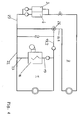
- a heat supply system designed according to the invention has two consumer circuits.
- the one consumer circuit 1 is used to provide heat energy for a heating system, not shown.
- the second existing consumer circuit 2 is used to provide heat energy for hot water to provide hot water in a consumer system, not shown.
- the two condensing boilers 3 and 4 are hydraulically connected in parallel and are located in a flow 5 of the consumer circuit 2.
- About the flow line 5 are in series heat storage 6 and 7 and optionally a first of the hot water generation serving heat exchanger 8 and with this heat exchanger 8 in series , also the hot water treatment serving heat exchanger 9 upstream biased applied.
- a temperature-controlled three-way valve 10 is provided, which is arranged behind a feed line 11 to the heat accumulator 7, which can regulate both the flow to the first heat exchanger 8 and on the other hand can act on a bypass 12 to the return line 13.
- the return line 13 is connected on the return side to the heat storage 6.
- a feed pump 14 is provided, which is advantageously arranged between the three-way valve 10 and the first heat exchanger 8.
- a heat exchanger 15 is provided, which is located after the integration of the storage return line 13.2 in the return line 13.1 and before entering the condensing boiler 4.
- This heat exchanger 15 is a heat energy exchange between the load circuit 1 and the load circuit. 2
- a condensing boiler higher capacity existing heat generator 16 In the consumer circuit 2 is to Breit ein of heating power for the heating system, not shown, from a condensing boiler higher capacity existing heat generator 16.
- This condensing boiler 16 is with its flow 17 via a three-way valve 18 both with a flow line 19.1 a heating system, not shown, as well as with a Feeding 19.2 connected to the heat exchanger 20 of the heat exchanger 15.
- the heat exchanger return 21 is connected to a return line 22.1 with the boiler return 23 as well as with the return line 24 from the consumer circuit 1 of the heating system.
- a feed pump 25 Before the feed of the return line 24 of the load circuit 1 of the heating device, not shown, in the boiler flow 17 of the condensing boiler 16, a feed pump 25 is provided.
- FIG. 6 An alternative to the embodiment of Fig. 6 shows the illustrated in Fig. 3, by the control valve 26 with switching function executable optional supply from the return 13.1 of the load circuit 2 with the opposite to the load circuit 1 elevated temperature level in the opposite of the return line 22 of the heat generator 16 raised return temperature level lying return boiler feed 28 of the heat generator 16.
- this solution variant is in operation an economic connection of the two lying on different temperature levels consumer circuits 1; 2 are supported.
- the supply circuits 1 and 2 are not hydraulically separated via a heat exchanger 15, but the return 13.1 of the supply circuit 2 with a relation to the supply circuit 1 higher temperature levels via a control valve 26 with switching function with the Infeed line 19.2 connected to the flow line 19.1 of the consumer circuit 1. Furthermore, the return 13.1 from the consumer circuit 2 via the control valve 26 with switching function both with the return feed 27 to the condensing boiler 3; 4 as well as with the return 22.1 of the supply circuit 1 connected. About the control valve 26 with switching function causes the load circuit 1 can be supplied at standstill of the condensing boiler 16 with heat energy.
- a power adjustment of the device according to the invention for thermal energy supply of at least two separate Verbtaucherniken for heating and hot water production can be done by any extension, since the already existing condensing boilers connected in parallel and thus can be retrofitted.
Landscapes
- Engineering & Computer Science (AREA)
- Physics & Mathematics (AREA)
- Thermal Sciences (AREA)
- Chemical & Material Sciences (AREA)
- Combustion & Propulsion (AREA)
- Mechanical Engineering (AREA)
- General Engineering & Computer Science (AREA)
- Water Supply & Treatment (AREA)
- Steam Or Hot-Water Central Heating Systems (AREA)
Applications Claiming Priority (1)
| Application Number | Priority Date | Filing Date | Title |
|---|---|---|---|
| DE102005046080A DE102005046080B4 (de) | 2005-09-26 | 2005-09-26 | Einrichtung zur Wärmeversorgung mit mindestens zwei getrennten, auf unterschiedlichen Temperaturebenen liegenden Verbraucherkreisen mit mindestens einem Wärmeerzeuger und Verfahren zum Betreiben der Einrichtung |
Publications (2)
| Publication Number | Publication Date |
|---|---|
| EP1795817A2 true EP1795817A2 (fr) | 2007-06-13 |
| EP1795817A3 EP1795817A3 (fr) | 2013-02-27 |
Family
ID=37698315
Family Applications (1)
| Application Number | Title | Priority Date | Filing Date |
|---|---|---|---|
| EP06018416A Withdrawn EP1795817A3 (fr) | 2005-09-26 | 2006-09-02 | Installation pour fournir de la chaleur avec au moins deux circiuts a des températures différentes avec au moins une source de chaleur et procédé de mise en oeuvre de l'installation. |
Country Status (2)
| Country | Link |
|---|---|
| EP (1) | EP1795817A3 (fr) |
| DE (1) | DE102005046080B4 (fr) |
Cited By (2)
| Publication number | Priority date | Publication date | Assignee | Title |
|---|---|---|---|---|
| CN108916968A (zh) * | 2018-08-24 | 2018-11-30 | 沈阳世杰电器有限公司 | 一种带有固体热能存储装置的供热系统 |
| CN111174266A (zh) * | 2020-02-20 | 2020-05-19 | 骆志成 | 多循环混合制自变流热水装置 |
Families Citing this family (2)
| Publication number | Priority date | Publication date | Assignee | Title |
|---|---|---|---|---|
| DE102007063137A1 (de) | 2007-12-24 | 2009-06-25 | Lang, Jürgen, Dipl.-Ing. | Wärmeversorgungsanlage mit mindestens zwei Wärmeerzeugern für mindestens zwei auf unterschiedlichen Temperaturebenen arbeitende Wärmeenergieversorgungskreise und Verfahren zur verbrauchsabhängigen Regelung der Wärmeerzeuger |
| CZ31064U1 (cs) * | 2017-01-27 | 2017-10-03 | Almeva Ag | Sdružený systém ohřevu užitkové vody a otopného média pro domovní vytápění |
Family Cites Families (7)
| Publication number | Priority date | Publication date | Assignee | Title |
|---|---|---|---|---|
| DE2856018A1 (de) * | 1978-12-23 | 1980-07-10 | Bbc Brown Boveri & Cie | Anordnung zur regelung der waermeverteilung in einem solarhaus |
| DE9104689U1 (de) * | 1991-04-17 | 1991-06-20 | Höfer, Volker Maria, 5340 Bad Honnef | Vorrichtung zur Rückgewinnung von Wärme aus den Abgasen aus Feuerungsanlagen |
| CH689173A5 (de) * | 1994-05-27 | 1998-11-13 | Unical Ag | Heizungsanlage und Verfahren zu deren Betrieb. |
| DE10055335A1 (de) * | 2000-11-08 | 2002-05-29 | Pro Solar Energietechnik Gmbh | Zentralheizungssystem mit Wärmespeicherung |
| DE10244339A1 (de) * | 2002-09-24 | 2004-04-01 | Robert Bosch Gmbh | Heizungsanlage für ein Gebäude |
| DE10349258B3 (de) * | 2003-10-20 | 2005-02-17 | Vertrieb und Großhandel von Heizungs-, Sanitär- und Elektroerzeugnissen | Wärmeversorgungsanlage mit mindestens zwei Wärmeerzeugern für eine Heizungsanlage und einer Einrichtung zur Warmwassererzeugung und Verfahren zur verbrauchsabhängigen Steuerung der Wärmeerzeuger |
| DE102004038768B4 (de) * | 2003-10-20 | 2008-03-06 | Vertrieb und Großhandel von Heizungs-, Sanitär- und Elektroerzeugnissen | Wärmeversorgungsanlage mit mindestens zwei Wärmeerzeugern für eine Heizungsanlage und einer Einrichtung zur Warmwassererzeugung und Verfahren zur verbrauchsabhängigen Steuerung der Wärmeerzeuger |
-
2005
- 2005-09-26 DE DE102005046080A patent/DE102005046080B4/de not_active Expired - Fee Related
-
2006
- 2006-09-02 EP EP06018416A patent/EP1795817A3/fr not_active Withdrawn
Cited By (2)
| Publication number | Priority date | Publication date | Assignee | Title |
|---|---|---|---|---|
| CN108916968A (zh) * | 2018-08-24 | 2018-11-30 | 沈阳世杰电器有限公司 | 一种带有固体热能存储装置的供热系统 |
| CN111174266A (zh) * | 2020-02-20 | 2020-05-19 | 骆志成 | 多循环混合制自变流热水装置 |
Also Published As
| Publication number | Publication date |
|---|---|
| EP1795817A3 (fr) | 2013-02-27 |
| DE102005046080B4 (de) | 2007-09-20 |
| DE102005046080A1 (de) | 2007-04-05 |
Similar Documents
| Publication | Publication Date | Title |
|---|---|---|
| EP2363650B1 (fr) | Groupe de production de chaleur doté d'un réglage de pompes à jet | |
| EP2154436B1 (fr) | Procédé et dispositif pour l'utilisation de chaleur | |
| EP2138775A2 (fr) | Agencement et procédé de préparation d'eau potable chaude à l'aide de caloporteur | |
| EP2354677A1 (fr) | Système à triple ou quadruple conducteur destiné à l'économie d'énergie pour chauffages urbains | |
| WO2009147136A1 (fr) | Arrangement de conduites pour équilibrer la température de deux circuits d’équilibrage de la température de bâtiments | |
| DE102009004501A1 (de) | Wärmepumpe und Verfahren zur Regelung der Quelleneingangstemperatur an der Wärmepumpe | |
| EP2287547B1 (fr) | Pompe à chaleur et procédé de réglage de la température d'entrée de sources sur une pompe à chaleur | |
| EP1795817A2 (fr) | Installation pour fournir de la chaleur avec au moins deux circiuts a des températures différentes avec au moins une source de chaleur et procédé de mise en oeuvre de l'installation. | |
| AT505065B1 (de) | Verfahren zur bereitstellung von thermischer energie | |
| DE3311127C2 (de) | Verfahren zur Regelung von im Verbund geschalteten, mit einem Pufferspeicher verbundenen Wärmeerzeugern und Anordnung zur Durchführung des Verfahrens | |
| DE19527830C2 (de) | Verfahren zum Betrieb einer Heizanlage und Heizanlage | |
| DE2916530A1 (de) | Verfahren und einrichtung zur erzeugung und verteilung thermischer energie mit kompensationsverlagerung in geothermische schichten | |
| DE102007048728B4 (de) | Heizkessel, Heizungsanlage sowie Verfahren zum Betreiben einer Heizungsanlage, insbesondere zur solaren Heizungsunterstützung | |
| EP0961082B1 (fr) | Installation de chauffage et de préparation d'eau chaude | |
| DE102021211129A1 (de) | Hybridheizsystem zum Bereitstellen von Brauchwasser und Heizungswärme | |
| AT511697B1 (de) | Vorrichtung zur erwärmung von brauchwasser | |
| WO2010094282A2 (fr) | Installation de chauffage et de refroidissement et procédé pour faire fonctionner une installation de chauffage et de refroidissement | |
| DE10349258B3 (de) | Wärmeversorgungsanlage mit mindestens zwei Wärmeerzeugern für eine Heizungsanlage und einer Einrichtung zur Warmwassererzeugung und Verfahren zur verbrauchsabhängigen Steuerung der Wärmeerzeuger | |
| DE102008061135A1 (de) | Verfahren zum Steuern oder Regeln einer Heizungsanlage und Heizanlage | |
| EP1526338B1 (fr) | Circuit d'alimentation de chauffage avec au moins deux générateurs de chaleur et procédé pour la commande des générateurs de chaleur en fonction de la consommation | |
| DE102006023627B4 (de) | Solaranlage | |
| DE20305438U1 (de) | Sammel- und Verteileinrichtung | |
| EP2189730A2 (fr) | Système d'alimentation d'un consommateur de chaleur et procédé de fonctionnement d'un tel système | |
| DE102009038738A1 (de) | Heizungsanlage | |
| AT526249B1 (de) | Verfahren zum Temperieren von Gebäuderäumen |
Legal Events
| Date | Code | Title | Description |
|---|---|---|---|
| PUAI | Public reference made under article 153(3) epc to a published international application that has entered the european phase |
Free format text: ORIGINAL CODE: 0009012 |
|
| AK | Designated contracting states |
Kind code of ref document: A2 Designated state(s): AT BE BG CH CY CZ DE DK EE ES FI FR GB GR HU IE IS IT LI LT LU LV MC NL PL PT RO SE SI SK TR |
|
| AX | Request for extension of the european patent |
Extension state: AL BA HR MK YU |
|
| RAP1 | Party data changed (applicant data changed or rights of an application transferred) |
Owner name: VERTRIEB UND GROSSHANDEL VON HEIZUNGS-, SANITAER- |
|
| RIC1 | Information provided on ipc code assigned before grant |
Ipc: F24D 3/02 20060101ALI20121005BHEP Ipc: F24D 3/08 20060101ALI20121005BHEP Ipc: F24D 12/02 20060101AFI20121005BHEP Ipc: F24D 19/10 20060101ALI20121005BHEP |
|
| PUAL | Search report despatched |
Free format text: ORIGINAL CODE: 0009013 |
|
| AK | Designated contracting states |
Kind code of ref document: A3 Designated state(s): AT BE BG CH CY CZ DE DK EE ES FI FR GB GR HU IE IS IT LI LT LU LV MC NL PL PT RO SE SI SK TR |
|
| AX | Request for extension of the european patent |
Extension state: AL BA HR MK RS |
|
| RIC1 | Information provided on ipc code assigned before grant |
Ipc: F24D 3/08 20060101ALI20130122BHEP Ipc: F24D 12/02 20060101AFI20130122BHEP Ipc: F24D 3/02 20060101ALI20130122BHEP Ipc: F24D 19/10 20060101ALI20130122BHEP |
|
| RAP1 | Party data changed (applicant data changed or rights of an application transferred) |
Owner name: SCHRAMM, BRUNO |
|
| AKY | No designation fees paid | ||
| REG | Reference to a national code |
Ref country code: DE Ref legal event code: R108 |
|
| REG | Reference to a national code |
Ref country code: DE Ref legal event code: R108 Effective date: 20131030 |
|
| STAA | Information on the status of an ep patent application or granted ep patent |
Free format text: STATUS: THE APPLICATION IS DEEMED TO BE WITHDRAWN |
|
| 18D | Application deemed to be withdrawn |
Effective date: 20130828 |