EP1798342A2 - Vorrichtung zum Zerlegen und Transportieren einer Ölbohrplattform - Google Patents
Vorrichtung zum Zerlegen und Transportieren einer Ölbohrplattform Download PDFInfo
- Publication number
- EP1798342A2 EP1798342A2 EP07002269A EP07002269A EP1798342A2 EP 1798342 A2 EP1798342 A2 EP 1798342A2 EP 07002269 A EP07002269 A EP 07002269A EP 07002269 A EP07002269 A EP 07002269A EP 1798342 A2 EP1798342 A2 EP 1798342A2
- Authority
- EP
- European Patent Office
- Prior art keywords
- shuttle
- support column
- hull
- lifting
- bridge
- Prior art date
- Legal status (The legal status is an assumption and is not a legal conclusion. Google has not performed a legal analysis and makes no representation as to the accuracy of the status listed.)
- Granted
Links
Images






Classifications
-
- B—PERFORMING OPERATIONS; TRANSPORTING
- B63—SHIPS OR OTHER WATERBORNE VESSELS; RELATED EQUIPMENT
- B63B—SHIPS OR OTHER WATERBORNE VESSELS; EQUIPMENT FOR SHIPPING
- B63B35/00—Vessels or similar floating structures specially adapted for specific purposes and not otherwise provided for
- B63B35/003—Vessels or similar floating structures specially adapted for specific purposes and not otherwise provided for for transporting very large loads, e.g. offshore structure modules
-
- B—PERFORMING OPERATIONS; TRANSPORTING
- B63—SHIPS OR OTHER WATERBORNE VESSELS; RELATED EQUIPMENT
- B63B—SHIPS OR OTHER WATERBORNE VESSELS; EQUIPMENT FOR SHIPPING
- B63B77/00—Transporting or installing offshore structures on site using buoyancy forces, e.g. using semi-submersible barges, ballasting the structure or transporting of oil-and-gas platforms
-
- B—PERFORMING OPERATIONS; TRANSPORTING
- B63—SHIPS OR OTHER WATERBORNE VESSELS; RELATED EQUIPMENT
- B63B—SHIPS OR OTHER WATERBORNE VESSELS; EQUIPMENT FOR SHIPPING
- B63B35/00—Vessels or similar floating structures specially adapted for specific purposes and not otherwise provided for
- B63B35/28—Barges or lighters
-
- B—PERFORMING OPERATIONS; TRANSPORTING
- B63—SHIPS OR OTHER WATERBORNE VESSELS; RELATED EQUIPMENT
- B63B—SHIPS OR OTHER WATERBORNE VESSELS; EQUIPMENT FOR SHIPPING
- B63B35/00—Vessels or similar floating structures specially adapted for specific purposes and not otherwise provided for
- B63B35/44—Floating buildings, stores, drilling platforms, or workshops, e.g. carrying water-oil separating devices
-
- E—FIXED CONSTRUCTIONS
- E02—HYDRAULIC ENGINEERING; FOUNDATIONS; SOIL SHIFTING
- E02B—HYDRAULIC ENGINEERING
- E02B17/00—Artificial islands mounted on piles or like supports, e.g. platforms on raisable legs or offshore constructions; Construction methods therefor
-
- E—FIXED CONSTRUCTIONS
- E02—HYDRAULIC ENGINEERING; FOUNDATIONS; SOIL SHIFTING
- E02B—HYDRAULIC ENGINEERING
- E02B17/00—Artificial islands mounted on piles or like supports, e.g. platforms on raisable legs or offshore constructions; Construction methods therefor
- E02B17/02—Artificial islands mounted on piles or like supports, e.g. platforms on raisable legs or offshore constructions; Construction methods therefor placed by lowering the supporting construction to the bottom, e.g. with subsequent fixing thereto
- E02B17/021—Artificial islands mounted on piles or like supports, e.g. platforms on raisable legs or offshore constructions; Construction methods therefor placed by lowering the supporting construction to the bottom, e.g. with subsequent fixing thereto with relative movement between supporting construction and platform
-
- E—FIXED CONSTRUCTIONS
- E02—HYDRAULIC ENGINEERING; FOUNDATIONS; SOIL SHIFTING
- E02B—HYDRAULIC ENGINEERING
- E02B17/00—Artificial islands mounted on piles or like supports, e.g. platforms on raisable legs or offshore constructions; Construction methods therefor
- E02B17/04—Equipment specially adapted for raising, lowering, or immobilising the working platform relative to the supporting construction
- E02B17/08—Equipment specially adapted for raising, lowering, or immobilising the working platform relative to the supporting construction for raising or lowering
-
- E—FIXED CONSTRUCTIONS
- E02—HYDRAULIC ENGINEERING; FOUNDATIONS; SOIL SHIFTING
- E02B—HYDRAULIC ENGINEERING
- E02B17/00—Artificial islands mounted on piles or like supports, e.g. platforms on raisable legs or offshore constructions; Construction methods therefor
- E02B17/04—Equipment specially adapted for raising, lowering, or immobilising the working platform relative to the supporting construction
- E02B17/08—Equipment specially adapted for raising, lowering, or immobilising the working platform relative to the supporting construction for raising or lowering
- E02B17/0818—Equipment specially adapted for raising, lowering, or immobilising the working platform relative to the supporting construction for raising or lowering with racks actuated by pinions
-
- E—FIXED CONSTRUCTIONS
- E02—HYDRAULIC ENGINEERING; FOUNDATIONS; SOIL SHIFTING
- E02B—HYDRAULIC ENGINEERING
- E02B17/00—Artificial islands mounted on piles or like supports, e.g. platforms on raisable legs or offshore constructions; Construction methods therefor
- E02B2017/0039—Methods for placing the offshore structure
- E02B2017/0047—Methods for placing the offshore structure using a barge
-
- E—FIXED CONSTRUCTIONS
- E02—HYDRAULIC ENGINEERING; FOUNDATIONS; SOIL SHIFTING
- E02B—HYDRAULIC ENGINEERING
- E02B17/00—Artificial islands mounted on piles or like supports, e.g. platforms on raisable legs or offshore constructions; Construction methods therefor
- E02B2017/0052—Removal or dismantling of offshore structures from their offshore location
-
- E—FIXED CONSTRUCTIONS
- E02—HYDRAULIC ENGINEERING; FOUNDATIONS; SOIL SHIFTING
- E02B—HYDRAULIC ENGINEERING
- E02B17/00—Artificial islands mounted on piles or like supports, e.g. platforms on raisable legs or offshore constructions; Construction methods therefor
- E02B2017/0056—Platforms with supporting legs
- E02B2017/006—Platforms with supporting legs with lattice style supporting legs
Definitions
- the present invention relates to a structure for transporting, installing and dismantling a fixed offshore oil platform comprising framework elements formed in particular by a bridge and at least one support column.
- It also relates to a method for transporting, installing and dismantling a support column of a fixed oil platform.
- a fixed oil platform that includes a bridge including operating equipment and living quarters.
- the bridge is supported by a support column anchored on the seabed.
- the first method consists of using lifting cranes mounted on barges to deposit the support column on the seabed and to transfer the deck of the platform of the transport boat onto this support column. This method, which until now is the most widespread, has limitations.
- the first of these limitations is the capacity of the hoisting cranes that may require the bridge to be made up of several elements, which significantly increases the cost of manufacturing this bridge and the cost of installing and dismantling the bridge. of the oil rig.
- the second limitation lies in the fact that this method requires a relatively large window of favorable time to be able to carry out the various operations of transfer at sea in good conditions.
- the second method is to install the support column on the seabed by lifting cranes and install the deck of the oil platform in a single block on the support column by floating above it. Then, the bridge is disposed on this support column either by a ballast / deballasting system, or by a mechanical system.
- the deck of the platform is supported either by a floating support constituted for example by a barge, pontoons or by a U-shaped floating support, or by means of a structure associated with this floating support.
- the superstructure can be ballasted or unballasted
- the superstructure having a large ballast capacity, the dismantling operation can proceed relatively quickly.
- the deballasting capacity of the floating support may be used. This capacity being limited, the operation proceeds slowly.
- ballast / deballasting system is the use of a mechanical system to raise or lower the deck of the platform oil. These systems make it possible to carry out the installation or dismantling operation of the deck of the oil platform faster than the systems mentioned above.
- Another mechanical system consists of a rack and pinion system to raise or lower the deck of the oil platform.
- the object of the invention is to propose a structure for transporting, installing or dismantling a fixed offshore oil platform which is designed to simplify and reduce the duration of dismantling of said platform, while by saving a lot of time and avoiding all risks of environmental pollution and increasing the security of the personnel responsible for carrying out the various operations.
- the invention also relates to a method of dismantling and transport and a method of transporting and installing a support column.
- FIG. 1 there is shown schematically a fixed oil platform generally designated by the reference 1 and comprising frame elements formed in particular by a bridge 2 provided with operating equipment and usual living quarters and a support column 3 on The base of this column 3 is anchored to the seabed 4 by anchoring members 5.
- the structure 10 comprises a U-shaped floating hull 11 equipped with lifting legs 12 of this hull 11 and adapted to bear on the seabed 4.
- the hull 11 comprises two lateral portions 11a. and a connecting portion 11b connecting the two side portions 11a.
- the shell 11 is equipped with three lifting legs 12 distributed in a triangle, one leg 12 being placed on each side portion 11a and one leg 12 being placed on the connecting portion 11b.
- the shell 11 may be equipped with four lifting legs 12 arranged in pairs on each lateral branch 11a of said shell 11.
- Each leg 12 ends at its lower end by a shoe 13 intended to bear on the seabed 4.
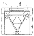
- each of these legs 12 has, in this embodiment, a triangular section. These legs 12 may also have a square or circular section. Each leg 12 is formed of three ribs 14 interconnected by a lattice of metal beams 15.
- each leg 12 is associated with mechanical means 20 for moving the shell 11.
- the mechanical displacement means 20 are housed in a supporting frame 16, also called by the specialists "Jack-house", which is supported by the hull 11.
- each frame 14 of each leg 12 has two opposite plates 21 each having, on each side face, a series of teeth 22 forming with the two members 14 a double rack.
- the mechanical means of displacement 20 of the shell 11 comprise several sets 25 distributed on either side of each plate 21, according to the height thereof.
- Each set 25 comprises a geared motor unit 26 for driving a pinion 27 which meshes with a series of teeth 22 of the corresponding plate 21.
- the two sets of teeth 22 of each plate 21 are associated with six pinions 27 each driven in rotation by a geared motor unit 26.
- the structure 10 also comprises a shuttle designated by the general reference 30 which is movable along the legs 12 independently of the shell 11 of the structure 10 and which is intended to move the support column 3, as will be seen later.
- the shuttle 30 is composed of independent elements 31 whose number corresponds to the number of legs 12 of the structure 10.
- the shuttle 30 is composed of three independent elements 31, each associated with a lifting leg 12.
- each element 31 of the shuttle 30 comprises mechanical means 40 for driving on the lifting leg 12 corresponding, independently of the shell 11 of the structure 10, as well as means of connection with the element d frame 2 or 3 to move from platform 1.
- the element 31 comprises a vertical guide branch 32 on the supporting framework 16 of the shell 11 and which is thus supported on a vertical wall 16a of this supporting framework 16.
- the element 31 also comprises a horizontal branch 33 which has a central opening 34 for the passage of the leg 12 corresponding.
- This horizontal branch 33 is disposed at the upper part of the vertical branch 32 and supports the mechanical means 40 driving said element 31 on the leg 12.
- the mechanical means 40 for driving each element 31 on the corresponding leg 12 operate independently of the mechanical means 20 for moving the shell 11 and these means 40 of the set of elements 31 operate in synchronization with each other so as to to obtain the same displacement of each element 31 on the corresponding leg 12.
- the mechanical means 40 for moving each element 31 of the shuttle 30 comprise several sets 41 distributed on either side of each plate 21 of the frame 14, depending on the height thereof.
- Each set 41 comprises a geared motor unit 42 driving a pinion 43 which meshes with a series of teeth 22 of the corresponding plate 21.
- the two series of teeth 22 of each plate 21 are associated with four pinions 43 each rotated by a geared motor unit 42.
- the vertical wall 16a of the supporting frame 16 forming a guide for the vertical displacement of the corresponding element 31 is extended, at its upper part, by a vertical plate 17 on which the element 31 slides so as to increase the height vertical displacement of this element 31.
- the means for moving the bridge 2 of the oil platform 1 is constituted by a horizontal support plate 50 of the bridge 2 during its transport, as will be seen later.
- the means for moving the support column 3 consist of a linear and vertical traction member 51 formed by a chain or a cable.
- the traction member 51 is constituted by a chain.
- the chain 51 can be wound on a drum 52 placed in the shell 11 of the structure 10 and comprises a first rising portion 51a which passes through the supporting frame 16 of the shell 11, the horizontal branch 33 of the element 31 and opens at the upper part of the vertical branch 31 of the element 30.
- the chain 51 passes on a return pulley 53 and has a descending portion 51b which passes through the vertical leg 32 of the element 31 and runs along the hull 11 where it is guided by a pulley 54 attached to the hull 11.
- the end of the chain 51 is equipped with a hooking system 55, of known type, on the support column 3 during its movement.
- the chain 51 is associated with two locking assemblies 60 and 65, one 60 being mounted on the element 31 and the other 65 being mounted on the shell 11. These two assemblies 60 and 65 operate independently of one another. other thus making it possible to secure the chain 51 with the element 31 or with the shell 11.
- FIG. 6 we will describe an example of a locking assembly for example the locking assembly 60, the locking assembly 65 being identical.
- the locking assembly 60 is formed of two subsets, 61a and 61b respectively, identical and symmetrical.
- the first subassembly 61a is formed by a latch 62a pivotably mounted on a base 63a about a horizontal axis 64a carried by the base 63a.
- the tilting of the lock 62a between a raised position and a lowered position is controlled by a jack 65a, for example hydraulic or pneumatic, one end of which is secured to the base 63a and whose other end is integral with the lock 62a.
- the second subassembly 61b is constituted by a latch 62b mounted tiltable on a base 63b about a horizontal axis 64b carried by said base 63b.
- the tilting of the lock 62b between a lowered position and a raised position is controlled by a jack 65b, for example hydraulic or pneumatic, one end of which is secured to the base 63b and whose other end is secured to the lock 62b.
- the displacement of the locks 62a and 62b is simultaneous.
- the latches 62a and 62b block the chain 51, as shown in FIG. 6.
- the opening of the "U" of the shell 11 of the structure 10 may be closed off by an independent branch 70 which may carry a crane 71 for moving modules of the oil platform 1 or of another platform. form next to which the transport structure 10 can be installed.
- this branch 70 can be installed by a barge, not shown, ballastable / deballastable and can be locked and unlocked from the hull 11 of the structure 10.
- the structure 10 allows the dismantling of a support column 3.
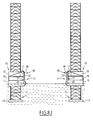
- the structure 10 is floated around the support column 3, as shown in FIG. 8A.
- the upper end of the section of the support column 3 is hooked by cables 56 to the shell 11 and these cables 56 are wound on drums 57 so as to allow their extension.
- the locking assembly 60 of each element 31 of the shuttle 30 is actuated by tilting the latches so as to secure the chains 51 and, as a result, the support column 3 of these elements. lock 65 are in the open position to allow the sliding of the chains 51.
- the elements 31 of the shuttle 30 are lifted by rotating the pinions 43 by means of the geared motor units 42 and meshing with the series of teeth 22 of the plates 21 of each lifting leg 12. Because of the solidarity chains 51 with these elements 31, the section of the support column 3 is also raised. During this movement, the elements 31 of the shuttle 30 are first guided towards the vertical wall 16a of the supporting frame 16 of the shell 11 and the plates 17, as shown in FIG. 8C. After this first lifting operation of the section of the support column 3, the locking assemblies 65 are actuated in order to lock the chains 51 and to secure these chains 51 of the shell 11. The locking assemblies 60 are opened by tilting the locks in order to release the chains 51 from the elements 31 of the shuttle 30. These elements 31 are lowered to bring them substantially to the level of the shell 11, as shown in FIG. 8D.
- the chains 51 are again secured to the elements 31 by locking assemblies 60 and these chains 51 are released from the shell 11 by opening the assemblies 65.
- the elements 31 of the shuttle 30 are lifted so as to lift also the section of the column support 3 and these operations are renewed to gradually lift this section, as shown in FIG. 8E.
- the elements 31 of the shuttle 30 carrying the section of the support column 3 are brought substantially at the level of the shell 11 (FIG 8F) and the assembly formed by the shuttle 30 and the shell 11 is lowered to bring this hull 11 in flotation, as shown in FIG. 8G.
- the legs 12 are raised and the structure 10 carrying the support column 3 is removed from the operating site by flotation (Fig. 8G).
- the structure 10 carrying the section of the support column 3 is floated to a loading site of this section on a barge 80.
- the lifting legs 12 are applied to the seabed 4 by rotating the gears 27 and 43 by the geared motors 26 and 42 and when the lifting legs 12 are in contact on the seabed 4, the hull 11 and the elements 31 of the shuttle 30 are raised in order to bring the lower end of the section of the support column 3 above the level of the water as shown in FIG. 8H.
- the barge 80 is brought below this section and said section is placed on the barge 80, then the chains 51 and the cables 56 are disconnected from the section of the support column 3 (FIG 9I).
- the hull 11 is then floated (FIG 9J) and the legs 12 are raised to allow the structure 10 to be used for a new transfer operation of the remaining part of the support column 3.
- the barge 80 carrying the section of the support column 3 is brought to a dismounting platform and this section is transferred to this platform, as shown in FIG. 9K.
- the structure 10 may also be used to remove the lower portion of the support column 3 or, if possible, to remove the entire support column 3 in a single operation.
- this structure 10 can also be used for laying a support column 3 of an oil platform on an operating site by performing substantially the same operations in the opposite direction.
- the structure according to the invention has the advantage of being able to transport the support column of an oil rig directly from the operating site to a fixed site where the dismantling can be carried out safely, without risk of pollution of the marine environment. or conversely between a fixed site and an exploitation site.
Landscapes
- Engineering & Computer Science (AREA)
- General Engineering & Computer Science (AREA)
- Mechanical Engineering (AREA)
- Civil Engineering (AREA)
- Structural Engineering (AREA)
- Chemical & Material Sciences (AREA)
- Combustion & Propulsion (AREA)
- Ocean & Marine Engineering (AREA)
- Transportation (AREA)
- Architecture (AREA)
- Earth Drilling (AREA)
- Bridges Or Land Bridges (AREA)
- Ship Loading And Unloading (AREA)
- Working Measures On Existing Buildindgs (AREA)
Applications Claiming Priority (2)
| Application Number | Priority Date | Filing Date | Title |
|---|---|---|---|
| FR0400806A FR2865484B1 (fr) | 2004-01-28 | 2004-01-28 | Structure de transport, d'installation et de demantelement des elements d'une plate-forme petroliere fixe et procedes de mise en oeuvre d'une telle structure. |
| EP04816494A EP1716293B1 (de) | 2004-01-28 | 2004-12-30 | Verfahren und Vorrichtung zum Demontieren einer Ölplattform |
Related Parent Applications (2)
| Application Number | Title | Priority Date | Filing Date |
|---|---|---|---|
| EP04816494A Division EP1716293B1 (de) | 2004-01-28 | 2004-12-30 | Verfahren und Vorrichtung zum Demontieren einer Ölplattform |
| EP04816494.1 Division | 2004-12-30 |
Publications (3)
| Publication Number | Publication Date |
|---|---|
| EP1798342A2 true EP1798342A2 (de) | 2007-06-20 |
| EP1798342A3 EP1798342A3 (de) | 2008-11-19 |
| EP1798342B1 EP1798342B1 (de) | 2011-12-21 |
Family
ID=34717471
Family Applications (2)
| Application Number | Title | Priority Date | Filing Date |
|---|---|---|---|
| EP04816494A Expired - Lifetime EP1716293B1 (de) | 2004-01-28 | 2004-12-30 | Verfahren und Vorrichtung zum Demontieren einer Ölplattform |
| EP07002269A Expired - Lifetime EP1798342B1 (de) | 2004-01-28 | 2004-12-30 | Vorrichtung zum Zerlegen und Transportieren einer Ölbohrplattform |
Family Applications Before (1)
| Application Number | Title | Priority Date | Filing Date |
|---|---|---|---|
| EP04816494A Expired - Lifetime EP1716293B1 (de) | 2004-01-28 | 2004-12-30 | Verfahren und Vorrichtung zum Demontieren einer Ölplattform |
Country Status (10)
| Country | Link |
|---|---|
| US (1) | US8070388B2 (de) |
| EP (2) | EP1716293B1 (de) |
| KR (1) | KR101230424B1 (de) |
| AT (2) | ATE404739T1 (de) |
| AU (1) | AU2004316316B2 (de) |
| BR (1) | BRPI0418459B1 (de) |
| DE (1) | DE602004015846D1 (de) |
| EA (1) | EA008616B1 (de) |
| FR (1) | FR2865484B1 (de) |
| WO (1) | WO2005083183A1 (de) |
Families Citing this family (41)
| Publication number | Priority date | Publication date | Assignee | Title |
|---|---|---|---|---|
| FR2837461B1 (fr) * | 2002-03-22 | 2004-06-18 | Technip Coflexip | Structure de transport, d'installation et de demantelement d'un pont d'une plate-forme petroliere fixe et procede de mise en oeuvre d'une telle structure |
| FR2921894B1 (fr) * | 2007-10-09 | 2011-03-25 | Technip France | Structure de transport, d'installation et de demantelement d'un pont d'une plate-forme petroliere et procedes de mise en oeuvre d'une telle structure |
| FR2932771B1 (fr) * | 2008-06-20 | 2010-06-04 | Technip France | Structure de transport et d'installation en mer d'au moins une eolienne ou hydrolienne et procedes de transport et d'installation en mer d'au moins une eolienne ou hydrolienne. |
| US7919664B2 (en) * | 2008-07-31 | 2011-04-05 | Chevron U.S.A. Inc. | Process for producing a jet fuel |
| DE202008012355U1 (de) * | 2008-09-17 | 2008-12-11 | Wärtsilä Ship Design Germany GmbH | Hubsystem |
| ES2381510B1 (es) * | 2008-10-22 | 2013-05-16 | Manuel Torres Martinez | Metodo para el montaje de aerogeneradores en lechos acuaticos y vehiculo para llevar a cabo dicho metodo |
| FR2946003B1 (fr) * | 2009-05-26 | 2012-12-14 | Technip France | Structure de transport, d'installation et de demantelement d'un pont d'une plate-forme et procedes de transport, d'installation et de demantelement de ce pont. |
| KR100946646B1 (ko) * | 2009-08-24 | 2010-03-10 | 삼보건설기계 주식회사 | 바지선의 승하강장치 |
| US9086057B2 (en) | 2010-01-21 | 2015-07-21 | The Abell Foundation, Inc. | Ocean thermal energy conversion cold water pipe |
| EP4273372A3 (de) | 2010-01-21 | 2024-01-24 | The Abell Foundation Inc. | Kraftwerk zur umwandlung von meereswärmeenergie |
| US8899043B2 (en) | 2010-01-21 | 2014-12-02 | The Abell Foundation, Inc. | Ocean thermal energy conversion plant |
| WO2011116254A2 (en) * | 2010-03-19 | 2011-09-22 | National Oilwell Varco, L.P. | Jack-up rig with leg-supported ballast loads |
| CN102346623A (zh) * | 2010-07-30 | 2012-02-08 | 歌尔声学股份有限公司 | 操控具有显示功能的主机的方法及其系统 |
| US8444347B2 (en) * | 2010-08-03 | 2013-05-21 | Technip France | Truss heave plate system for offshore platform |
| EP2426262B1 (de) * | 2010-09-01 | 2016-08-17 | Keppel Offshore&Marine Technology Centre Pte Ltd | Installationsschiff |
| KR101239321B1 (ko) * | 2010-10-07 | 2013-03-05 | 삼성중공업 주식회사 | 시추선 |
| GB2502463B (en) * | 2011-01-14 | 2016-04-20 | Glosten Solutions Inc | Installation method for water-submersible platforms and installation vessel |
| GB201109123D0 (en) * | 2011-05-27 | 2011-07-13 | Steven Iain | Mobile barge and method of operation of a mobile barge |
| US9151279B2 (en) | 2011-08-15 | 2015-10-06 | The Abell Foundation, Inc. | Ocean thermal energy conversion power plant cold water pipe connection |
| KR101313809B1 (ko) * | 2012-05-04 | 2013-09-30 | 삼성중공업 주식회사 | 잭업 플랫폼 |
| US9138817B1 (en) * | 2012-09-17 | 2015-09-22 | Jon Khachaturian | Method and apparatus for removing underwater platforms |
| WO2014043496A2 (en) * | 2012-09-17 | 2014-03-20 | Technip France | Truss spar vortex induced vibration damping with vertical plates |
| BR112015008522B1 (pt) | 2012-10-16 | 2021-01-19 | The Abell Foundation, Inc. | placa de troca de calor e trocador de calor |
| SG2012086674A (en) * | 2012-11-23 | 2014-06-27 | Keppel Offshore & Marine Technology Ct Pte Ltd | Structure-supported jackup system |
| KR101431374B1 (ko) * | 2013-03-08 | 2014-08-19 | 주식회사 포스코플랜텍 | 잭-업 플랫폼 구동장치 |
| US9366091B2 (en) * | 2014-05-19 | 2016-06-14 | Conocophillips Company | Decommissioning offshore oil and gas wells |
| KR200481541Y1 (ko) * | 2014-12-03 | 2016-10-12 | 대우조선해양 주식회사 | 고정식 플랫폼의 자켓 리프트용 슬링 리테이너 및 그 슬링 리테이너를 구비하는 고정식 플랫폼 |
| RU2603423C1 (ru) * | 2015-07-22 | 2016-11-27 | Акционерное общество "Центральное конструкторское бюро "Коралл" | Морское самоходное самоподъемное крановое судно |
| CA3006734A1 (en) | 2015-12-01 | 2017-06-08 | Rowan Companies, Inc. | Dual operational rig |
| CN106245617B (zh) * | 2016-07-27 | 2019-01-18 | 金海重工(舟山)设计研究院有限公司 | 一种海上升降平台系统 |
| US10302068B2 (en) * | 2016-10-31 | 2019-05-28 | Zentech, Inc. | Conversion of movable offshore drilling structure to wind turbine application |
| NL2018499B1 (en) * | 2017-03-10 | 2018-09-21 | Gustomsc Resources Bv | Method for monitoring movement of a cantilever structure of an offshore platform, monitoring system, offshore platform |
| FR3067047B1 (fr) * | 2017-06-06 | 2019-07-26 | Ideol | Procede de mise a l'eau |
| US10415204B1 (en) * | 2018-04-30 | 2019-09-17 | Northern Offshore Ltd. | Multi-environment self-elevating drilling platform |
| NL2021625B1 (en) * | 2018-09-13 | 2020-05-06 | Gustomsc Resources Bv | Controlling movement of a cantilever structure of an offshore platform |
| DK180667B1 (en) | 2019-04-01 | 2021-11-12 | Phoenix Ii As | A method of securing and transferring a load between a vessel and an offshore installation and an apparatus therefor |
| DK180345B1 (en) | 2019-04-01 | 2021-01-15 | Maersk Supply Service As | A method of securing and transferring a load between a vessel and an offshore installation and an apparatus therefor |
| RU2719053C1 (ru) * | 2019-09-26 | 2020-04-17 | Федеральное государственное унитарное предприятие "Крыловский государственный научный центр" (ФГУП Крыловский государственный научный центр") | Устройство транспортировки добычного модуля и установки его на плаву на стационарное морское опорное основание одноколонного типа |
| US20210156156A1 (en) * | 2019-11-27 | 2021-05-27 | OM Engineering Pty Ltd | Independent self-climbing form system for building vertical structures |
| NO346577B1 (en) * | 2020-12-21 | 2022-10-17 | Aker Offshore Wind Operating Company As | Construction of offshore wind power plants |
| CN116201092B (zh) * | 2023-03-06 | 2025-08-26 | 南方科技大学 | 用于海上自升式平台的格构式箍板及安装方法 |
Family Cites Families (6)
| Publication number | Priority date | Publication date | Assignee | Title |
|---|---|---|---|---|
| US2308743A (en) * | 1939-09-16 | 1943-01-19 | William P Bulkley | Barge |
| NL135005C (de) * | 1967-10-11 | 1972-09-15 | ||
| US4456404A (en) * | 1982-02-17 | 1984-06-26 | Atlantic Pacific Marine Corporation | Method and apparatus for positioning a working barge above a sea surface |
| NL8800664A (nl) * | 1988-03-17 | 1989-10-16 | Darya Paye Jetty Co Ltd | Werkwijze en inrichting voor het vervaardigen van een waterbouwkundige constructie, zoals een pijler, steiger en dergelijke. |
| FR2657904B1 (fr) * | 1990-02-08 | 1992-12-31 | Technip Geoproduction | Dispositif de surcharge d'une plate-forme petroliere auto-elevatrice et plate-forme en comportant application. |
| FR2837461B1 (fr) * | 2002-03-22 | 2004-06-18 | Technip Coflexip | Structure de transport, d'installation et de demantelement d'un pont d'une plate-forme petroliere fixe et procede de mise en oeuvre d'une telle structure |
-
2004
- 2004-01-28 FR FR0400806A patent/FR2865484B1/fr not_active Expired - Fee Related
- 2004-12-30 AT AT04816494T patent/ATE404739T1/de not_active IP Right Cessation
- 2004-12-30 BR BRPI0418459A patent/BRPI0418459B1/pt not_active IP Right Cessation
- 2004-12-30 WO PCT/FR2004/003418 patent/WO2005083183A1/fr not_active Ceased
- 2004-12-30 US US10/587,589 patent/US8070388B2/en not_active Expired - Fee Related
- 2004-12-30 EA EA200601376A patent/EA008616B1/ru not_active IP Right Cessation
- 2004-12-30 DE DE602004015846T patent/DE602004015846D1/de not_active Expired - Fee Related
- 2004-12-30 KR KR1020067015248A patent/KR101230424B1/ko not_active Expired - Fee Related
- 2004-12-30 EP EP04816494A patent/EP1716293B1/de not_active Expired - Lifetime
- 2004-12-30 EP EP07002269A patent/EP1798342B1/de not_active Expired - Lifetime
- 2004-12-30 AT AT07002269T patent/ATE538256T1/de active
- 2004-12-30 AU AU2004316316A patent/AU2004316316B2/en not_active Ceased
Also Published As
| Publication number | Publication date |
|---|---|
| EP1798342B1 (de) | 2011-12-21 |
| US8070388B2 (en) | 2011-12-06 |
| FR2865484B1 (fr) | 2006-05-19 |
| US20080131209A1 (en) | 2008-06-05 |
| EA200601376A1 (ru) | 2007-02-27 |
| KR101230424B1 (ko) | 2013-02-06 |
| ATE404739T1 (de) | 2008-08-15 |
| EP1716293B1 (de) | 2008-08-13 |
| AU2004316316B2 (en) | 2010-03-11 |
| DE602004015846D1 (de) | 2008-09-25 |
| AU2004316316A1 (en) | 2005-09-09 |
| EP1798342A3 (de) | 2008-11-19 |
| BRPI0418459B1 (pt) | 2015-10-20 |
| FR2865484A1 (fr) | 2005-07-29 |
| EP1716293A1 (de) | 2006-11-02 |
| KR20070006723A (ko) | 2007-01-11 |
| BRPI0418459A (pt) | 2007-06-05 |
| WO2005083183A1 (fr) | 2005-09-09 |
| EA008616B1 (ru) | 2007-06-29 |
| ATE538256T1 (de) | 2012-01-15 |
Similar Documents
| Publication | Publication Date | Title |
|---|---|---|
| EP1798342B1 (de) | Vorrichtung zum Zerlegen und Transportieren einer Ölbohrplattform | |
| EP1487693B1 (de) | Konstruktion für den transport, die installation und die zerlegung einer brücke einer festen ölplattform und verfahren zur implementierung der konstruktion | |
| EP2435293B1 (de) | Struktur zum transportieren, installieren und demontieren des decks einer plattform und verfahren zum transportieren, installieren und demontieren eines solches decks | |
| EP2285665B1 (de) | Struktur zum transportieren und installieren oder bergung von unterwasserausrüstung und verfahren zum transportieren und installieren oder bergen von unterwasserausrüstung | |
| WO2009153530A2 (fr) | Structure de transport et d'installation en mer d'au moins une éolienne ou hydrolienne et procédés de transport et d'installation en mer d'au moins une éolienne ou hydrolienne | |
| EP2091808A1 (de) | Struktur für transport, installation und demontage einer ölproduktionsplattform und verfahren zur verwendung einer solchen struktur | |
| WO1983001235A1 (fr) | Dispositif flottant de levage et de transport de charge | |
| EP0979923A1 (de) | Einrichtung zur Ausbeutung einer Erdöllagerstätte in der See und Verfahren zur Aufstellung eines Risers | |
| EP0745729B1 (de) | Selbsthebende Plattform für Bohren oder Ölgewinnung aus dem Meer | |
| CA2280403C (fr) | Procede d'implantation d'une installation d'exploitation | |
| EP1204806B1 (de) | Schwimmende träger mit einem zentralhohlraum, der aus einer vielzahl von fächern besteht | |
| BE887882A (fr) | Structure pour supporter un appareillage au-dessus du fond d'une masse d'eau | |
| EP1458609B1 (de) | Verfahren zum anbringen von schweren ausrüstungen an einem schiffsrumpf | |
| FR2921894A1 (fr) | Structure de transport, d'installation et de demantelement d'un pont d'une plate-forme petroliere et procedes de mise en oeuvre d'une telle structure | |
| WO1979000016A1 (fr) | Procedure de mise en place d'une structure support de torchere pour plate-forme petroliere | |
| EP4408734B1 (de) | System und verfahren zum einbringen einer schweren last in wasser | |
| EP0097069B1 (de) | Verfahren zum Installieren einer Plattform im Meer, Plattformüberbau zum Ausführen dieses Verfahrens | |
| FR2596083A1 (fr) | Procede pour l'assemblage et l'installation d'une plate-forme metallique en mer | |
| FR2595106A1 (fr) | Procede pour la construction d'une plate-forme marine gravitaire | |
| FR2798683A1 (fr) | Procede d'installation d'une plate-forme gravitaire d'exploitation d'un champ petrolier en mer | |
| MXPA06008393A (en) | Structure for transporting, installing and dismantling the elements of a fixed oil platform and methods for using said structure |
Legal Events
| Date | Code | Title | Description |
|---|---|---|---|
| PUAI | Public reference made under article 153(3) epc to a published international application that has entered the european phase |
Free format text: ORIGINAL CODE: 0009012 |
|
| 17P | Request for examination filed |
Effective date: 20070202 |
|
| AC | Divisional application: reference to earlier application |
Ref document number: 1716293 Country of ref document: EP Kind code of ref document: P |
|
| AK | Designated contracting states |
Kind code of ref document: A2 Designated state(s): AT BE BG CH CY CZ DE DK EE ES FI FR GB GR HU IE IS IT LI LT LU MC NL PL PT RO SE SI SK TR |
|
| PUAL | Search report despatched |
Free format text: ORIGINAL CODE: 0009013 |
|
| AK | Designated contracting states |
Kind code of ref document: A3 Designated state(s): AT BE BG CH CY CZ DE DK EE ES FI FR GB GR HU IE IS IT LI LT LU MC NL PL PT RO SE SI SK TR |
|
| RIC1 | Information provided on ipc code assigned before grant |
Ipc: E02B 17/08 20060101AFI20070503BHEP |
|
| 17Q | First examination report despatched |
Effective date: 20090205 |
|
| AKX | Designation fees paid |
Designated state(s): AT BE BG CH CY CZ DE DK EE ES FI FR GB GR HU IE IS IT LI LT LU MC NL PL PT RO SE SI SK TR |
|
| GRAP | Despatch of communication of intention to grant a patent |
Free format text: ORIGINAL CODE: EPIDOSNIGR1 |
|
| GRAS | Grant fee paid |
Free format text: ORIGINAL CODE: EPIDOSNIGR3 |
|
| GRAA | (expected) grant |
Free format text: ORIGINAL CODE: 0009210 |
|
| AC | Divisional application: reference to earlier application |
Ref document number: 1716293 Country of ref document: EP Kind code of ref document: P |
|
| AK | Designated contracting states |
Kind code of ref document: B1 Designated state(s): AT BE BG CH CY CZ DE DK EE ES FI FR GB GR HU IE IS IT LI LT LU MC NL PL PT RO SE SI SK TR |
|
| REG | Reference to a national code |
Ref country code: GB Ref legal event code: FG4D Free format text: NOT ENGLISH |
|
| REG | Reference to a national code |
Ref country code: CH Ref legal event code: EP |
|
| REG | Reference to a national code |
Ref country code: AT Ref legal event code: REF Ref document number: 538256 Country of ref document: AT Kind code of ref document: T Effective date: 20120115 |
|
| REG | Reference to a national code |
Ref country code: IE Ref legal event code: FG4D |
|
| REG | Reference to a national code |
Ref country code: NL Ref legal event code: T3 |
|
| REG | Reference to a national code |
Ref country code: DE Ref legal event code: R096 Ref document number: 602004035820 Country of ref document: DE Effective date: 20120301 |
|
| PG25 | Lapsed in a contracting state [announced via postgrant information from national office to epo] |
Ref country code: LT Free format text: LAPSE BECAUSE OF FAILURE TO SUBMIT A TRANSLATION OF THE DESCRIPTION OR TO PAY THE FEE WITHIN THE PRESCRIBED TIME-LIMIT Effective date: 20111221 |
|
| LTIE | Lt: invalidation of european patent or patent extension |
Effective date: 20111221 |
|
| PG25 | Lapsed in a contracting state [announced via postgrant information from national office to epo] |
Ref country code: SE Free format text: LAPSE BECAUSE OF FAILURE TO SUBMIT A TRANSLATION OF THE DESCRIPTION OR TO PAY THE FEE WITHIN THE PRESCRIBED TIME-LIMIT Effective date: 20111221 Ref country code: GR Free format text: LAPSE BECAUSE OF FAILURE TO SUBMIT A TRANSLATION OF THE DESCRIPTION OR TO PAY THE FEE WITHIN THE PRESCRIBED TIME-LIMIT Effective date: 20120322 Ref country code: SI Free format text: LAPSE BECAUSE OF FAILURE TO SUBMIT A TRANSLATION OF THE DESCRIPTION OR TO PAY THE FEE WITHIN THE PRESCRIBED TIME-LIMIT Effective date: 20111221 |
|
| PG25 | Lapsed in a contracting state [announced via postgrant information from national office to epo] |
Ref country code: CY Free format text: LAPSE BECAUSE OF FAILURE TO SUBMIT A TRANSLATION OF THE DESCRIPTION OR TO PAY THE FEE WITHIN THE PRESCRIBED TIME-LIMIT Effective date: 20111221 |
|
| BERE | Be: lapsed |
Owner name: TECHNIP FRANCE Effective date: 20111231 |
|
| REG | Reference to a national code |
Ref country code: IE Ref legal event code: FD4D |
|
| PG25 | Lapsed in a contracting state [announced via postgrant information from national office to epo] |
Ref country code: MC Free format text: LAPSE BECAUSE OF NON-PAYMENT OF DUE FEES Effective date: 20111231 Ref country code: IS Free format text: LAPSE BECAUSE OF FAILURE TO SUBMIT A TRANSLATION OF THE DESCRIPTION OR TO PAY THE FEE WITHIN THE PRESCRIBED TIME-LIMIT Effective date: 20120421 Ref country code: IE Free format text: LAPSE BECAUSE OF FAILURE TO SUBMIT A TRANSLATION OF THE DESCRIPTION OR TO PAY THE FEE WITHIN THE PRESCRIBED TIME-LIMIT Effective date: 20111221 Ref country code: CZ Free format text: LAPSE BECAUSE OF FAILURE TO SUBMIT A TRANSLATION OF THE DESCRIPTION OR TO PAY THE FEE WITHIN THE PRESCRIBED TIME-LIMIT Effective date: 20111221 Ref country code: EE Free format text: LAPSE BECAUSE OF FAILURE TO SUBMIT A TRANSLATION OF THE DESCRIPTION OR TO PAY THE FEE WITHIN THE PRESCRIBED TIME-LIMIT Effective date: 20111221 Ref country code: BG Free format text: LAPSE BECAUSE OF FAILURE TO SUBMIT A TRANSLATION OF THE DESCRIPTION OR TO PAY THE FEE WITHIN THE PRESCRIBED TIME-LIMIT Effective date: 20120321 Ref country code: SK Free format text: LAPSE BECAUSE OF FAILURE TO SUBMIT A TRANSLATION OF THE DESCRIPTION OR TO PAY THE FEE WITHIN THE PRESCRIBED TIME-LIMIT Effective date: 20111221 |
|
| REG | Reference to a national code |
Ref country code: CH Ref legal event code: PL |
|
| PG25 | Lapsed in a contracting state [announced via postgrant information from national office to epo] |
Ref country code: PL Free format text: LAPSE BECAUSE OF FAILURE TO SUBMIT A TRANSLATION OF THE DESCRIPTION OR TO PAY THE FEE WITHIN THE PRESCRIBED TIME-LIMIT Effective date: 20111221 Ref country code: PT Free format text: LAPSE BECAUSE OF FAILURE TO SUBMIT A TRANSLATION OF THE DESCRIPTION OR TO PAY THE FEE WITHIN THE PRESCRIBED TIME-LIMIT Effective date: 20120423 Ref country code: RO Free format text: LAPSE BECAUSE OF FAILURE TO SUBMIT A TRANSLATION OF THE DESCRIPTION OR TO PAY THE FEE WITHIN THE PRESCRIBED TIME-LIMIT Effective date: 20111221 |
|
| REG | Reference to a national code |
Ref country code: AT Ref legal event code: MK05 Ref document number: 538256 Country of ref document: AT Kind code of ref document: T Effective date: 20111221 |
|
| REG | Reference to a national code |
Ref country code: DE Ref legal event code: R119 Ref document number: 602004035820 Country of ref document: DE Effective date: 20120703 |
|
| PLBE | No opposition filed within time limit |
Free format text: ORIGINAL CODE: 0009261 |
|
| STAA | Information on the status of an ep patent application or granted ep patent |
Free format text: STATUS: NO OPPOSITION FILED WITHIN TIME LIMIT |
|
| PG25 | Lapsed in a contracting state [announced via postgrant information from national office to epo] |
Ref country code: DE Free format text: LAPSE BECAUSE OF NON-PAYMENT OF DUE FEES Effective date: 20120703 Ref country code: BE Free format text: LAPSE BECAUSE OF NON-PAYMENT OF DUE FEES Effective date: 20111231 Ref country code: DK Free format text: LAPSE BECAUSE OF FAILURE TO SUBMIT A TRANSLATION OF THE DESCRIPTION OR TO PAY THE FEE WITHIN THE PRESCRIBED TIME-LIMIT Effective date: 20111221 Ref country code: CH Free format text: LAPSE BECAUSE OF NON-PAYMENT OF DUE FEES Effective date: 20111231 Ref country code: LI Free format text: LAPSE BECAUSE OF NON-PAYMENT OF DUE FEES Effective date: 20111231 |
|
| 26N | No opposition filed |
Effective date: 20120924 |
|
| PG25 | Lapsed in a contracting state [announced via postgrant information from national office to epo] |
Ref country code: IT Free format text: LAPSE BECAUSE OF FAILURE TO SUBMIT A TRANSLATION OF THE DESCRIPTION OR TO PAY THE FEE WITHIN THE PRESCRIBED TIME-LIMIT Effective date: 20111221 |
|
| PG25 | Lapsed in a contracting state [announced via postgrant information from national office to epo] |
Ref country code: AT Free format text: LAPSE BECAUSE OF FAILURE TO SUBMIT A TRANSLATION OF THE DESCRIPTION OR TO PAY THE FEE WITHIN THE PRESCRIBED TIME-LIMIT Effective date: 20111221 |
|
| PG25 | Lapsed in a contracting state [announced via postgrant information from national office to epo] |
Ref country code: ES Free format text: LAPSE BECAUSE OF FAILURE TO SUBMIT A TRANSLATION OF THE DESCRIPTION OR TO PAY THE FEE WITHIN THE PRESCRIBED TIME-LIMIT Effective date: 20120401 |
|
| PG25 | Lapsed in a contracting state [announced via postgrant information from national office to epo] |
Ref country code: LU Free format text: LAPSE BECAUSE OF NON-PAYMENT OF DUE FEES Effective date: 20111230 |
|
| PG25 | Lapsed in a contracting state [announced via postgrant information from national office to epo] |
Ref country code: FI Free format text: LAPSE BECAUSE OF FAILURE TO SUBMIT A TRANSLATION OF THE DESCRIPTION OR TO PAY THE FEE WITHIN THE PRESCRIBED TIME-LIMIT Effective date: 20111221 |
|
| PG25 | Lapsed in a contracting state [announced via postgrant information from national office to epo] |
Ref country code: TR Free format text: LAPSE BECAUSE OF FAILURE TO SUBMIT A TRANSLATION OF THE DESCRIPTION OR TO PAY THE FEE WITHIN THE PRESCRIBED TIME-LIMIT Effective date: 20111221 |
|
| PG25 | Lapsed in a contracting state [announced via postgrant information from national office to epo] |
Ref country code: HU Free format text: LAPSE BECAUSE OF FAILURE TO SUBMIT A TRANSLATION OF THE DESCRIPTION OR TO PAY THE FEE WITHIN THE PRESCRIBED TIME-LIMIT Effective date: 20111221 |
|
| REG | Reference to a national code |
Ref country code: FR Ref legal event code: PLFP Year of fee payment: 12 |
|
| PGFP | Annual fee paid to national office [announced via postgrant information from national office to epo] |
Ref country code: GB Payment date: 20151218 Year of fee payment: 12 |
|
| PGFP | Annual fee paid to national office [announced via postgrant information from national office to epo] |
Ref country code: NL Payment date: 20151116 Year of fee payment: 12 |
|
| PGFP | Annual fee paid to national office [announced via postgrant information from national office to epo] |
Ref country code: FR Payment date: 20151231 Year of fee payment: 12 |
|
| REG | Reference to a national code |
Ref country code: NL Ref legal event code: MM Effective date: 20170101 |
|
| GBPC | Gb: european patent ceased through non-payment of renewal fee |
Effective date: 20161230 |
|
| PG25 | Lapsed in a contracting state [announced via postgrant information from national office to epo] |
Ref country code: NL Free format text: LAPSE BECAUSE OF NON-PAYMENT OF DUE FEES Effective date: 20170101 |
|
| REG | Reference to a national code |
Ref country code: FR Ref legal event code: ST Effective date: 20170831 |
|
| PG25 | Lapsed in a contracting state [announced via postgrant information from national office to epo] |
Ref country code: FR Free format text: LAPSE BECAUSE OF NON-PAYMENT OF DUE FEES Effective date: 20170102 |
|
| PG25 | Lapsed in a contracting state [announced via postgrant information from national office to epo] |
Ref country code: GB Free format text: LAPSE BECAUSE OF NON-PAYMENT OF DUE FEES Effective date: 20161230 |