EP1798366A2 - Entraînement de volet roulant avec sangle mince et liaison de sangle - Google Patents
Entraînement de volet roulant avec sangle mince et liaison de sangle Download PDFInfo
- Publication number
- EP1798366A2 EP1798366A2 EP06025289A EP06025289A EP1798366A2 EP 1798366 A2 EP1798366 A2 EP 1798366A2 EP 06025289 A EP06025289 A EP 06025289A EP 06025289 A EP06025289 A EP 06025289A EP 1798366 A2 EP1798366 A2 EP 1798366A2
- Authority
- EP
- European Patent Office
- Prior art keywords
- belt
- drive
- roller shutter
- coupling
- thin
- Prior art date
- Legal status (The legal status is an assumption and is not a legal conclusion. Google has not performed a legal analysis and makes no representation as to the accuracy of the status listed.)
- Withdrawn
Links
Images

Classifications
-
- E—FIXED CONSTRUCTIONS
- E06—DOORS, WINDOWS, SHUTTERS, OR ROLLER BLINDS IN GENERAL; LADDERS
- E06B—FIXED OR MOVABLE CLOSURES FOR OPENINGS IN BUILDINGS, VEHICLES, FENCES OR LIKE ENCLOSURES IN GENERAL, e.g. DOORS, WINDOWS, BLINDS, GATES
- E06B9/00—Screening or protective devices for wall or similar openings, with or without operating or securing mechanisms; Closures of similar construction
- E06B9/56—Operating, guiding or securing devices or arrangements for roll-type closures; Spring drums; Tape drums; Counterweighting arrangements therefor
- E06B9/68—Operating devices or mechanisms, e.g. with electric drive
- E06B9/70—Operating devices or mechanisms, e.g. with electric drive comprising an electric motor positioned outside the roller
-
- A—HUMAN NECESSITIES
- A44—HABERDASHERY; JEWELLERY
- A44B—BUTTONS, PINS, BUCKLES, SLIDE FASTENERS, OR THE LIKE
- A44B11/00—Buckles; Similar fasteners for interconnecting straps or the like, e.g. for safety belts
- A44B11/25—Buckles; Similar fasteners for interconnecting straps or the like, e.g. for safety belts with two or more separable parts
- A44B11/258—Buckles; Similar fasteners for interconnecting straps or the like, e.g. for safety belts with two or more separable parts fastening by superposing one part on top of the other
- A44B11/2588—Buckles; Similar fasteners for interconnecting straps or the like, e.g. for safety belts with two or more separable parts fastening by superposing one part on top of the other combined with one buckle element rotating or pivoting
-
- E—FIXED CONSTRUCTIONS
- E06—DOORS, WINDOWS, SHUTTERS, OR ROLLER BLINDS IN GENERAL; LADDERS
- E06B—FIXED OR MOVABLE CLOSURES FOR OPENINGS IN BUILDINGS, VEHICLES, FENCES OR LIKE ENCLOSURES IN GENERAL, e.g. DOORS, WINDOWS, BLINDS, GATES
- E06B9/00—Screening or protective devices for wall or similar openings, with or without operating or securing mechanisms; Closures of similar construction
- E06B9/56—Operating, guiding or securing devices or arrangements for roll-type closures; Spring drums; Tape drums; Counterweighting arrangements therefor
- E06B9/78—Operating, guiding or securing devices or arrangements for roll-type closures; Spring drums; Tape drums; Counterweighting arrangements therefor for direct manual operation, e.g. by tassels, by handles
- E06B2009/785—Operating, guiding or securing devices or arrangements for roll-type closures; Spring drums; Tape drums; Counterweighting arrangements therefor for direct manual operation, e.g. by tassels, by handles by belts, straps, bands, tapes, cords, tassels
Definitions
- the invention relates to a darkening device for windows, in particular shutters.
- the device in question is particularly suitable for retrofitting a roller shutter with a motor drive.
- Motorized drives for roller shutters are available both as drives which directly drive the roller shutter winding with roll motors and as drives which indirectly drive the roller shutter winding over a belt.
- the belt is driven by a belt winder or actuated by a friction gear.
- a drive device for roller shutters with a belt actuation with a Gurtwickler is concerned with a drive device for roller shutters with a belt actuation with a Gurtwickler.
- the drive device is predestined as a retrofit unit and can operate the roller shutter motor. The point here is to greatly reduce the installation space of the drive device and in particular to reduce the installation effort when installing the shutter drive on the window, that the drive device to be mounted does not have to be opened.
- roller shutter drives that use a belt as a traction device for power transmission, can be divided into take-up drives in which a winding drum is driven and in friction wheel drives that drive the belt frictionally.
- the friction wheel drive is with respect to the transmittable force limited.
- All known motorized roller shutter drives use the belt existing on the building side.
- the belt When installing a roller shutter drive with a Gurtwicklerantrieb the belt must be solved on the existing Gurtwickler to be attached to the driven winding drum of the roller shutter drive.
- the advantage of the high transferable force due to the positive connection between the belt and the driven drum is opposed both by the disadvantage of the higher assembly costs due to the required belt fastening and the disadvantage of the large space requirement for the winding drum.
- the stated aim of the present patent application is to realize a highly resilient, positive winding drive, which does not have the disadvantage of the usual, expensive belt assembly and has a smaller footprint than usual.
- the space requirement is very important if you want to allow all possible and thus the smallest standardized wall shafts for receiving the roller shutter drive.
- the device must usually be opened for the positive mounting of the belt on the winding drum of the motorized belt drive, which makes various security measures in the electrical device required.
- this is about retrofittable roller shutter drives with a belt drive.
- the present protective rights are intended to enable the low assembly costs and the low volume of construction in a form-fitting, retrofit winding drive, that the building side existing belt of the shutter is not identical to the traction means, which is used to generate the driving forces and is wound in the shutter drive.
- the novel device has a Gurtverlauf between the drive and the shutter which consists of two series-connected belts, a building-side belt, the beginning of the roller shutter drum is fixed and a drive-side belt, the beginning of which is connected to the motor-operated device. Both straps are coupled at the ends when mounting the drive. For this purpose, a detachable, positive coupling is provided.
- the device side strap is about the same width, but very thin and high strength. These types of thin straps would be completely useless for manual operation. However, since the manual operation is to be eliminated by the installation of a motor drive brings a thinner, smooth, not handy belt with no disadvantages.
- the main advantage of the thin belt is the reduction of the winding diameter in the roller shutter drive and the associated reduced space, since the winding drum in the drive significantly determines the overall volume of the drive device.
- the device according to the invention consists of a motor-driven drive with a belt installed on the device side with a belt coupling for attachment to the building-side roller shutter belt.
- a roller shutter drive with a device side installable belt the goal of realizing a small Aufwickel mismessers the belt and thus the feasibility of a small size device is realized in that the roller shutter drive uses a traction mechanism, which halves the drive side required belt path for the operation of the shutter and reduces the winding diameter by reducing the required belt length.
- the present inventive device realizes a small size of the device in that a small Aufwickel malmesser the belt is not achieved by reducing the Gurthubes, but only by the use of a high-strength, thin belt.
- a reduction in the webbing thickness results in a significant reduction of the winding diameter, which in the present inventive device an essential condition for reducing the space of the Shutter drive represents.
- the motorized roller shutter drive has a factory-installed, thin belt, it must be connected to the existing roller shutter on the window. This coupling point between the thin belt on the device and the conventional roller shutter on the window represents a thick spot in the entire belt, which should not run into the motorized shutter drive.
- the device according to the invention is very advantageous, since hereby a motorized roller shutter drive is easy to install and easy to remove.
- the straps are decoupled, the belt drive is removed, the original hand winder is replaced and the originally separate belt is coupled again.
- the coupling piece consists of two parts, a factory attached to the thin, motor-driven belt part and a, to be fastened to the window-side belt part.
- the bipartite coupling allows a releasable positive connection of the straps and thus results in easy handling during assembly and disassembly of the belt drive.
- An additional coupling piece is mounted on the disassembled belt of the hand winder to make the dismantling of the manual operation of the roller shutter during a change of residence easy.
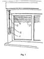
- the built-in motorized roller shutter drive (1) has a thin belt (2) as a traction device for operating the shutter (3).
- the on-site belt (4) operates the shutter (3).
- the on-site belt (4) and the thin belt of the motor-driven Roller shutter drive is coupled to the clutch (5) preferably releasably releasably.
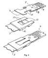
- FIG. 2 A preferred embodiment of the coupling (5) is shown in FIG 2.
- thin belt (2) is preferably a coupling element (6) made of plastic preferably molded.
- At the on-site belt (4) is preferably a coupling element (7) made of a thin sheet steel, preferably with rivets (8) attached.
- the tabs (9) of the elastically deformable steel sheet (7) are slipped behind the edges (10) of the coupling element (6) and the tabs (11) are snapped under the edges (12) of the coupling element (6).
- FIG. 3 shows a coupling for the connection of two conventional belts.
- the coupling elements are designed to be compatible with the coupling shown in FIG. This circumstance becomes necessary if, when dismantling the hand-operated roller shutter winder, provision is already made for dismantling to manual operation.
- the coupling element (7) is attached to the roller shutter side belt, which is compatible both to the coupling element (6) of the motor drive, as well as the coupling element (13) of the belt (14), which belongs to the developed hand winder.
Landscapes
- Engineering & Computer Science (AREA)
- Structural Engineering (AREA)
- Architecture (AREA)
- Civil Engineering (AREA)
- Operating, Guiding And Securing Of Roll- Type Closing Members (AREA)
Applications Claiming Priority (1)
| Application Number | Priority Date | Filing Date | Title |
|---|---|---|---|
| DE200510060261 DE102005060261B4 (de) | 2005-12-16 | 2005-12-16 | Rollladenantrieb mit dünnem Antriebsgurt und einer Gurtkupplung |
Publications (2)
| Publication Number | Publication Date |
|---|---|
| EP1798366A2 true EP1798366A2 (fr) | 2007-06-20 |
| EP1798366A3 EP1798366A3 (fr) | 2008-11-05 |
Family
ID=37897387
Family Applications (1)
| Application Number | Title | Priority Date | Filing Date |
|---|---|---|---|
| EP06025289A Withdrawn EP1798366A3 (fr) | 2005-12-16 | 2006-12-07 | Entraînement de volet roulant avec sangle mince et liaison de sangle |
Country Status (2)
| Country | Link |
|---|---|
| EP (1) | EP1798366A3 (fr) |
| DE (1) | DE102005060261B4 (fr) |
Cited By (2)
| Publication number | Priority date | Publication date | Assignee | Title |
|---|---|---|---|---|
| DE102013008464A1 (de) * | 2013-05-21 | 2014-11-27 | Björn Mohr | Haltevorrichtung zur zumindest mittelbaren Halterung eines Rollladengurtes an einer Rollladenwelle |
| EP3123892A1 (fr) * | 2015-07-28 | 2017-02-01 | Michel Hirschi | Fermoir pour pieces de joaillerie |
Family Cites Families (4)
| Publication number | Priority date | Publication date | Assignee | Title |
|---|---|---|---|---|
| JPS6225146Y2 (fr) * | 1980-09-29 | 1987-06-27 | ||
| DE8604210U1 (de) * | 1986-02-18 | 1986-05-28 | H. & E. Strack oHG, 5600 Wuppertal | Gurtverbinder |
| SE469950B (sv) * | 1992-02-28 | 1993-10-11 | Icl Data Ab | Skarvdon för kuggremmar |
| DE29613721U1 (de) * | 1996-08-08 | 1996-11-21 | Carl Stahl GmbH & Co KG, Gurt- und Bandweberei, 89542 Herbrechtingen | Austauschgurt |
-
2005
- 2005-12-16 DE DE200510060261 patent/DE102005060261B4/de not_active Expired - Fee Related
-
2006
- 2006-12-07 EP EP06025289A patent/EP1798366A3/fr not_active Withdrawn
Cited By (3)
| Publication number | Priority date | Publication date | Assignee | Title |
|---|---|---|---|---|
| DE102013008464A1 (de) * | 2013-05-21 | 2014-11-27 | Björn Mohr | Haltevorrichtung zur zumindest mittelbaren Halterung eines Rollladengurtes an einer Rollladenwelle |
| DE102013008464B4 (de) * | 2013-05-21 | 2019-09-19 | Björn Mohr | Haltevorrichtung zur zumindest mittelbaren Halterung eines Rollladengurtes an einer Rollladenwelle |
| EP3123892A1 (fr) * | 2015-07-28 | 2017-02-01 | Michel Hirschi | Fermoir pour pieces de joaillerie |
Also Published As
| Publication number | Publication date |
|---|---|
| EP1798366A3 (fr) | 2008-11-05 |
| DE102005060261B4 (de) | 2009-12-24 |
| DE102005060261A1 (de) | 2007-06-21 |
Similar Documents
| Publication | Publication Date | Title |
|---|---|---|
| DE2750904C2 (de) | Fensterheber, insbesondere für Kraftfahrzeuge | |
| EP3687844B1 (fr) | Systeme de store pour toit de vehicule | |
| DE102007012259A1 (de) | Sonnenschutzrollo für Kraftfahrzeuge | |
| DE2758874A1 (de) | Verbesserungen an mit drahtzug arbeitenden fensterhebern, insbesondere fuer kraftfahrzeuge | |
| DE102007057073B4 (de) | Abdecksystem für ein Fahrzeug | |
| DE102007057074A1 (de) | Rollosystem | |
| EP1700989A2 (fr) | Entraînement pour éléments fonctionnels mobiles dans un véhicule automobile | |
| DE10155167B4 (de) | Sonnenschutz-Rollanordnung für ein Fahrzeugdach | |
| DE102005036318A1 (de) | Fensterrollo mit glatten Schubgliedern | |
| EP1666292B1 (fr) | Système de protection solaire pour un toit de véhicule avec un couvercle transparent | |
| DE102019129887A1 (de) | Verriegelungseinrichtung für eine elektrische Anschlussvorrichtung für Elektro- oder Hybridfahrzeuge | |
| DE102005060261B4 (de) | Rollladenantrieb mit dünnem Antriebsgurt und einer Gurtkupplung | |
| EP1964700B1 (fr) | Store de fenêtre de véhicule | |
| EP1630341A1 (fr) | Rail de guidage de lève-vitre | |
| DE102005037324B4 (de) | Kraftübertragungselement, Fensterheber und Kraftfahrzeugtür mit einem Fensterheber | |
| DE202020105109U1 (de) | Handbetätigte, mechanische Antriebsvorrichtung | |
| DE202020105110U1 (de) | Handbetätigte, mechanische Antriebsvorrichtung | |
| EP3822444A1 (fr) | Entrainement d'une porte de véhicule, en particulier porte coulissante | |
| DE102007028967A1 (de) | Betätigungseinrichtung für eine Schiebetür | |
| DE10206161A1 (de) | Öffnungsfähiges Fahrzeugdach mit mindestens einem Deckel und zwei Abdeckeinrichtungen | |
| DE202023102539U1 (de) | Dachbaugruppe für ein Fahrzeug | |
| DE102012200037B4 (de) | Antriebsvorrichtung zum Auf- und Abwickeln einer Verdunkelungsvorrichtung | |
| DE102019107709A1 (de) | Schiebetürantrieb für ein kraftfahrzeug | |
| DE2007130A1 (de) | Antriebsvorrichtung für Schiebefenster, Schiebedächer und dergleichen von Kraftfahrzeugen | |
| DE102019127598B4 (de) | Antriebsanordnung für ein Schiebedach und ein Sonnenrollo eines Fahrzeugs |
Legal Events
| Date | Code | Title | Description |
|---|---|---|---|
| PUAI | Public reference made under article 153(3) epc to a published international application that has entered the european phase |
Free format text: ORIGINAL CODE: 0009012 |
|
| AK | Designated contracting states |
Kind code of ref document: A2 Designated state(s): AT BE BG CH CY CZ DE DK EE ES FI FR GB GR HU IE IS IT LI LT LU LV MC NL PL PT RO SE SI SK TR |
|
| AX | Request for extension of the european patent |
Extension state: AL BA HR MK YU |
|
| PUAL | Search report despatched |
Free format text: ORIGINAL CODE: 0009013 |
|
| AK | Designated contracting states |
Kind code of ref document: A3 Designated state(s): AT BE BG CH CY CZ DE DK EE ES FI FR GB GR HU IE IS IT LI LT LU LV MC NL PL PT RO SE SI SK TR |
|
| AX | Request for extension of the european patent |
Extension state: AL BA HR MK RS |
|
| AKX | Designation fees paid | ||
| STAA | Information on the status of an ep patent application or granted ep patent |
Free format text: STATUS: THE APPLICATION IS DEEMED TO BE WITHDRAWN |
|
| REG | Reference to a national code |
Ref country code: DE Ref legal event code: 8566 |
|
| 18D | Application deemed to be withdrawn |
Effective date: 20090507 |