EP1798593A1 - Affichage a cristaux liquides - Google Patents
Affichage a cristaux liquides Download PDFInfo
- Publication number
- EP1798593A1 EP1798593A1 EP05785710A EP05785710A EP1798593A1 EP 1798593 A1 EP1798593 A1 EP 1798593A1 EP 05785710 A EP05785710 A EP 05785710A EP 05785710 A EP05785710 A EP 05785710A EP 1798593 A1 EP1798593 A1 EP 1798593A1
- Authority
- EP
- European Patent Office
- Prior art keywords
- liquid crystal
- crystal display
- film
- light
- optically anisotropic
- Prior art date
- Legal status (The legal status is an assumption and is not a legal conclusion. Google has not performed a legal analysis and makes no representation as to the accuracy of the status listed.)
- Withdrawn
Links
Images




Classifications
-
- G—PHYSICS
- G02—OPTICS
- G02F—OPTICAL DEVICES OR ARRANGEMENTS FOR THE CONTROL OF LIGHT BY MODIFICATION OF THE OPTICAL PROPERTIES OF THE MEDIA OF THE ELEMENTS INVOLVED THEREIN; NON-LINEAR OPTICS; FREQUENCY-CHANGING OF LIGHT; OPTICAL LOGIC ELEMENTS; OPTICAL ANALOGUE/DIGITAL CONVERTERS
- G02F1/00—Devices or arrangements for the control of the intensity, colour, phase, polarisation or direction of light arriving from an independent light source, e.g. switching, gating or modulating; Non-linear optics
- G02F1/01—Devices or arrangements for the control of the intensity, colour, phase, polarisation or direction of light arriving from an independent light source, e.g. switching, gating or modulating; Non-linear optics for the control of the intensity, phase, polarisation or colour
- G02F1/13—Devices or arrangements for the control of the intensity, colour, phase, polarisation or direction of light arriving from an independent light source, e.g. switching, gating or modulating; Non-linear optics for the control of the intensity, phase, polarisation or colour based on liquid crystals, e.g. single liquid crystal display cells
- G02F1/133—Constructional arrangements; Operation of liquid crystal cells; Circuit arrangements
- G02F1/1333—Constructional arrangements; Manufacturing methods
- G02F1/1335—Structural association of cells with optical devices, e.g. polarisers or reflectors
- G02F1/133502—Antiglare, refractive index matching layers
-
- G—PHYSICS
- G02—OPTICS
- G02F—OPTICAL DEVICES OR ARRANGEMENTS FOR THE CONTROL OF LIGHT BY MODIFICATION OF THE OPTICAL PROPERTIES OF THE MEDIA OF THE ELEMENTS INVOLVED THEREIN; NON-LINEAR OPTICS; FREQUENCY-CHANGING OF LIGHT; OPTICAL LOGIC ELEMENTS; OPTICAL ANALOGUE/DIGITAL CONVERTERS
- G02F1/00—Devices or arrangements for the control of the intensity, colour, phase, polarisation or direction of light arriving from an independent light source, e.g. switching, gating or modulating; Non-linear optics
- G02F1/01—Devices or arrangements for the control of the intensity, colour, phase, polarisation or direction of light arriving from an independent light source, e.g. switching, gating or modulating; Non-linear optics for the control of the intensity, phase, polarisation or colour
- G02F1/13—Devices or arrangements for the control of the intensity, colour, phase, polarisation or direction of light arriving from an independent light source, e.g. switching, gating or modulating; Non-linear optics for the control of the intensity, phase, polarisation or colour based on liquid crystals, e.g. single liquid crystal display cells
- G02F1/133—Constructional arrangements; Operation of liquid crystal cells; Circuit arrangements
- G02F1/1333—Constructional arrangements; Manufacturing methods
- G02F1/1335—Structural association of cells with optical devices, e.g. polarisers or reflectors
-
- G—PHYSICS
- G02—OPTICS
- G02F—OPTICAL DEVICES OR ARRANGEMENTS FOR THE CONTROL OF LIGHT BY MODIFICATION OF THE OPTICAL PROPERTIES OF THE MEDIA OF THE ELEMENTS INVOLVED THEREIN; NON-LINEAR OPTICS; FREQUENCY-CHANGING OF LIGHT; OPTICAL LOGIC ELEMENTS; OPTICAL ANALOGUE/DIGITAL CONVERTERS
- G02F1/00—Devices or arrangements for the control of the intensity, colour, phase, polarisation or direction of light arriving from an independent light source, e.g. switching, gating or modulating; Non-linear optics
- G02F1/01—Devices or arrangements for the control of the intensity, colour, phase, polarisation or direction of light arriving from an independent light source, e.g. switching, gating or modulating; Non-linear optics for the control of the intensity, phase, polarisation or colour
- G02F1/13—Devices or arrangements for the control of the intensity, colour, phase, polarisation or direction of light arriving from an independent light source, e.g. switching, gating or modulating; Non-linear optics for the control of the intensity, phase, polarisation or colour based on liquid crystals, e.g. single liquid crystal display cells
- G02F1/133—Constructional arrangements; Operation of liquid crystal cells; Circuit arrangements
- G02F1/1333—Constructional arrangements; Manufacturing methods
- G02F1/1335—Structural association of cells with optical devices, e.g. polarisers or reflectors
- G02F1/13363—Birefringent elements, e.g. for optical compensation
-
- G—PHYSICS
- G02—OPTICS
- G02F—OPTICAL DEVICES OR ARRANGEMENTS FOR THE CONTROL OF LIGHT BY MODIFICATION OF THE OPTICAL PROPERTIES OF THE MEDIA OF THE ELEMENTS INVOLVED THEREIN; NON-LINEAR OPTICS; FREQUENCY-CHANGING OF LIGHT; OPTICAL LOGIC ELEMENTS; OPTICAL ANALOGUE/DIGITAL CONVERTERS
- G02F1/00—Devices or arrangements for the control of the intensity, colour, phase, polarisation or direction of light arriving from an independent light source, e.g. switching, gating or modulating; Non-linear optics
- G02F1/01—Devices or arrangements for the control of the intensity, colour, phase, polarisation or direction of light arriving from an independent light source, e.g. switching, gating or modulating; Non-linear optics for the control of the intensity, phase, polarisation or colour
- G02F1/13—Devices or arrangements for the control of the intensity, colour, phase, polarisation or direction of light arriving from an independent light source, e.g. switching, gating or modulating; Non-linear optics for the control of the intensity, phase, polarisation or colour based on liquid crystals, e.g. single liquid crystal display cells
- G02F1/133—Constructional arrangements; Operation of liquid crystal cells; Circuit arrangements
- G02F1/1333—Constructional arrangements; Manufacturing methods
- G02F1/1343—Electrodes
- G02F1/134309—Electrodes characterised by their geometrical arrangement
- G02F1/134363—Electrodes characterised by their geometrical arrangement for applying an electric field parallel to the substrate, i.e. in-plane switching [IPS]
-
- G—PHYSICS
- G02—OPTICS
- G02F—OPTICAL DEVICES OR ARRANGEMENTS FOR THE CONTROL OF LIGHT BY MODIFICATION OF THE OPTICAL PROPERTIES OF THE MEDIA OF THE ELEMENTS INVOLVED THEREIN; NON-LINEAR OPTICS; FREQUENCY-CHANGING OF LIGHT; OPTICAL LOGIC ELEMENTS; OPTICAL ANALOGUE/DIGITAL CONVERTERS
- G02F2201/00—Constructional arrangements not provided for in groups G02F1/00 - G02F7/00
- G02F2201/50—Protective arrangements
-
- G—PHYSICS
- G02—OPTICS
- G02F—OPTICAL DEVICES OR ARRANGEMENTS FOR THE CONTROL OF LIGHT BY MODIFICATION OF THE OPTICAL PROPERTIES OF THE MEDIA OF THE ELEMENTS INVOLVED THEREIN; NON-LINEAR OPTICS; FREQUENCY-CHANGING OF LIGHT; OPTICAL LOGIC ELEMENTS; OPTICAL ANALOGUE/DIGITAL CONVERTERS
- G02F2413/00—Indexing scheme related to G02F1/13363, i.e. to birefringent elements, e.g. for optical compensation, characterised by the number, position, orientation or value of the compensation plates
- G02F2413/02—Number of plates being 2
Definitions
- This invention relates to a liquid crystal display. More particularly it relates to a liquid crystal display exhibiting improved reflection prevention and abrasive resistance, and having minimized problems in the view angle characteristics, and thus, characterized in that when an image on the display is viewed from an oblique view angle, the reduction of contrast can be minimized without substantial deterioration of image characteristics as viewed perpendicularly, and good qualified images are manifested at black display for broad view angles, and homogeneous images with a high contrast are obtained.
- a liquid crystal display is characterized by high image quality, thin thickness, light weight and low electric power consumption, and is widely used for, for example, televisions, personal computers and car navigation equipments.
- a liquid crystal display has a pair of polarizers, the axes of polarity of which are perpendicular to each other, and between which a liquid crystal cell is sandwiched. By imposing a voltage to the liquid crystal cell, the orientation of liquid crystal molecules is varied whereby a picture appears.
- a twisted nematic display usually has a configuration such that, when a voltage is applied, liquid crystal molecules are aligned in the perpendicular direction to give a black display.
- An in-plane switching mode liquid crystal display usually has a configuration such that, when a voltage is not applied, the liquid crystal molecules are aligned in a certain direction and, when a voltage is applied, the alignment of liquid crystal molecules rotates by 45 degrees to give a white display.
- a liquid crystal display In a liquid crystal display, the axes of polarity of which are aligned in the perpendicular direction and a horizontal direction perpendicular to the perpendicular direction, in the case when the picture is viewed from the perpendicular direction or the horizontal direction, a high contrast is obtained.
- a high contrast is obtained.
- birefringence occurs in the transmissive light and leakage of light occurs, and therefore, a qualified black display is difficult to obtain, and the contrast of picture is deteriorated. Therefore, an attempt is made by providing the liquid crystal device with an optical compensation means to minimize the deterioration of the contrast of picture.
- an in-plane switching mode liquid crystal display has been proposed in Japanese Unexamined Patent Publication No. H11-305127 , pages 2-3 ( US Patent No. 6,285,430 ), which comprises a first polarizer plate, an optical compensation film, a first substrate, a liquid crystal layer, a second substrate and a second polarizer plate, disposed in this order, wherein one of the first and second polarizer plates has a transmission axis which is parallel to a liquid crystal retardation axis of the liquid crystal layer at a black display, and the other has a transmission axis which is perpendicular to the liquid crystal retardation axis of the liquid crystal layer at a black display; and wherein the angle formed by a film retardation axis of the optical compensation film and the transmission axis of one of the two polarizing plates is 0 to 2 degrees or 88 to 90 degrees.
- An object of the present invention is to provide a liquid crystal display exhibiting improved reflection prevention and abrasive resistance, and having minimized problems in the view angle characteristics, and thus, characterized in that when an image on the display is viewed from an oblique direction, the deterioration in contrast can be prevented or minimized without substantial deterioration of image characteristics as viewed perpendicularly, and well qualified images are manifested at black display for wide view angles, and homogeneous images with a high contrast are obtained.
- the present inventors made extensive searches and found that, in the case when an in-plane switching mode liquid crystal display having at least two optically anisotropic sheets and a liquid crystal cell between a pair of polarizers consisting of a light incident side polarizer and a light emission side polarizer satisfy a requirement such that the sum of the two in-plane principal refractive indexes of the optically anisotropic sheets is not larger than the double of the principal refractive index in the thickness direction, good qualified images are manifested at black display for wide view angles, and images with enhanced homogeneity and high contrast are obtained.
- the present invention has been completed based on this finding.
- liquid crystal displays as recited below.
- the liquid crystal display according to the present invention has enhanced abrasive resistance and a wide view angle, and characterized in that good qualified images are manifested at black display for wide view angles, and homogeneous images with a high contrast are obtained.
- the light transmission axis of the light incident side polarizer and the light transmission axis of the light emission side polarizer are substantially perpendicular to each other, more specifically cross preferably at an intersecting angle of 87 to 90 degrees, more preferably 89 to 90 degrees, as expressed by the angles ranging 0 to 90 degrees.
- intersecting angle refers to an angle defined by the two planes, each of which has each light transmission axis as normal line.
- the optically anisotropic sheets are comprised of different substances so that at least one of the principal refractive indexes n x , n y and n z is different from the others.
- n x , n y and n z is different from the others.
- the arrangement of k sheets of optically anisotropic bodies and a liquid crystal cell between a pair of polarizers is not particularly limited, and thus, k optically anisotropic sheets and a liquid crystal cell can be arranged at a voluntarily position.
- the multilayered body may take any arrangement of (1) optically anisotropic sheet-liquid crystal cell-anisotropic sheet, (2) anisotropic sheet-anisotropic sheet-liquid crystal cell, and (3) liquid crystal cell-anisotropic sheet-anisotropic sheet, as the order disposed from the light incident side to the light emission side.
- the liquid crystal display satisfy the following inequality: ⁇ ⁇ n xi + ⁇ ⁇ n yi / 2 > ⁇ ⁇ n zi when the display surface is viewed obliquely, the image quality at black display tends to be deteriorated and the contrast is liable to be reduced.
- contrast ratio CF
- Y off is a luminance at dark display of the liquid crystal display
- Y on is a luminance at light display of the liquid crystal display. The larger the contrast ratio, the better the visibility.
- the light display refers to the lightest state of display surface of the liquid crystal display
- the black display refers to the darkest state of display surface of the liquid crystal display.
- polar angle as used in this description we mean a viewing angle at which the display surface is viewed at an angle inclined from the perpendicular line to the display surface.
- a multilayered optical body (A) consisting of the k optically anisotropic sheets and the liquid crystal cell satisfies the following formula: 0.90 ⁇ R 40 / R 0 ⁇ 1.10 wherein R 0 is a retardation when light having a wavelength of 550 nm impinges vertically, and R 40 is a retardation when light having a wavelength of 550 nm impinges at an inclination angle of 40 degrees from the normal to the direction of the principal axis.
- the multilayered optical body (A) preferably satisfies the following formula: 0.92 ⁇ R 40 / R 0 ⁇ 1.08 , and more preferably satisfies the following formula: 0.95 ⁇ R 40 / R 0 ⁇ 1.05.
- the retardation R 40 as a retardation when light having a wavelength of 550 nm impinges at an inclination angle of 40 degrees from the normal to the direction of the principal axis is preferably measured on two directions, i.e., a direction of polar angle ⁇ wherein light is on Y-Z plane as the slow axis of a multilayered optical body (A) illustrated in Fig. 1 being a rotation axis, and a direction of polar angle ⁇ wherein light is on X-Z plane as the fast of the multilayered optical body (A) being a rotation axis.
- the ratio of R 40 /R 0 is smaller than 0.90 or larger than 1.10, and the difference between R 0 (i.e., a retardation when light having a wavelength of 550 nm impinges perpendicularly) and R 40 (i.e., a retardation when light having a wavelength of 550 nm impinges at an inclination angle of 40 degrees from the normal to the direction of the principal axis), when the display surface is viewed from the oblique direction, qualified images cannot be manifested at black display, and the contrast tends to be reduced.
- the light transmission axis of the light emission side polarizer and/or the light transmission axis of the light incident side polarizer, and the slow axis of the multilayered optical body (A) are substantially parallel or substantially perpendicular to each other.
- substantially parallel we mean that each light transmission axis and the slow axis cross at an intersecting angle of 0 to 3 degrees, preferably 0 to 1 degree, as expressed by the angles ranging 0 to 90 degrees.
- each light transmission axis and the slow axis cross at an intersecting angle of 87 to 90 degrees, preferably 89 to 90 degree, as expressed by the angles ranging 0 to 90 degrees. If the light transmission axis of the light emission side polarizer and/or the light transmission axis of the light incident side polarizer, and the slow axis of the multilayered optical body (A) cross at an intersecting angle of larger than 3 degrees and smaller than 87 degrees, light leaks and qualified images become difficult to obtain at black display.
- the slow axis of the optically anisotropic sheets and the slow axis of liquid crystal molecules within the liquid crystal cell in a voltage non-imposed state are substantially parallel or substantially perpendicular to each other.
- substantially parallel we mean that the two slow axes cross at an intersecting angle of 0 to 3 degrees, preferably 0 to 1 degree, as expressed by the angles ranging 0 to 90 degrees.
- substantially perpendicular as used herein we mean that the two slow axes cross at an intersecting angle of 87 to 90 degrees, preferably 89 to 90 degree, as expressed by the angles ranging 0 to 90 degrees.
- the liquid crystal display of the present invention becomes a black display in a voltage non-imposed state.
- At least one of the optically anisotropic sheets is a layer composed of a material with a minus intrinsic birefringence value, or a layer comprising discotic liquid crystal molecules or lyotropic liquid crystal molecules, or a layer comprising a photo-isomerizing substance.
- the material with a minus intrinsic birefringence value refers to a material having a characteristic such that, when light is incident on a layer wherein molecules are oriented in a uniaxial order, the refractive index of light in the direction parallel to the molecule orientation is smaller than the refractive index of light in the direction perpendicular to the molecule direction.
- the material having a minus intrinsic birefringence value includes, for example, aromatic vinyl polymers, acrylonitrile polymers, methyl methacrylate polymers, cellulose esters, and copolymers of these polymeric materials.
- aromatic vinyl polymers, acrylonitrile polymers and methyl methacrylate polymers are preferable.
- Aromatic vinyl polymers are especially preferable because a high birefringence is manifested.
- polystyrene As specific examples of the aromatic vinyl polymers, there can be mentioned polystyrene; and copolymers of an aromatic vinyl monomer such as ⁇ -methylstyrene, p-methylstyrene, p-chlorostyrene, p-nitrostyrene, p-aminostyrene, p-vinylbenzoic acid or p-phenylstyrene with other monomers such as ethylene, propylene, butadiene, isoprene, acrylonitrile, methacrylonitrile, ⁇ -chloroacylonitrile, methyl acrylate, ethyl acrylate, methyl methacrylate, ethyl methacrylate, acrylic acid, methacrylic acid, maleic anhydride or vinyl acetate.
- polystyrene and a styrene-maleic anhydride copolymer are preferably used.
- the method of forming a layer containing the material having a minus intrinsic birefringence value is not particularly limited, but, a method of stretching a film comprised of a polymeric material having a minus intrinsic birefringence value is preferably adopted.
- a method of stretching a film comprised of a polymeric material having a minus intrinsic birefringence value is preferably adopted.
- the stretched film containing the polymeric material having a minus intrinsic birefringence value can be laminated onto another film.
- a polymer film containing the polymeric material having a minus intrinsic birefringence value can be laminated onto another polymeric material film via an adhesive resin layer to form a multilayered structure, and the multilayered structure is stretched to thereby form the layer containing the material having a minus intrinsic birefringence value.
- the layer containing the material having a minus intrinsic birefringence value can be obtained from a polymeric material film with a minus intrinsic birefringence value, the strength of which is too poor to stretch the film alone.
- optically anisotropic sheets satisfying the following formula: ⁇ ⁇ n xi + ⁇ ⁇ n yi / 2 ⁇ ⁇ ⁇ n zi can be obtained stably without breakage of film at a temperature under which a birefringence is easily manifested.
- the method of stretching the polymer film having a minus intrinsic birefringence value or the above-mentioned multilayered structure is not particularly limited.
- a uniaxial stretching method wherein the stretching is carried out in the lengthwise direction utilizing the difference in peripheral speed between rollers or stretched in the transverse direction using a tenter
- a concurrent biaxial stretching method wherein the stretching is carried out in the lengthwise direction by enlarging the distance between the adjacent grips tightly holding the film or the multilayered structure, concurrently with in the transverse direction by utilizing the angle between two guide rails, or a sequential biaxial stretching method wherein the stretching is carried out in the lengthwise direction utilizing the difference in peripheral speed between rollers, and then in the transverse direction using a tenter while the distance between grips on both sides tightly holding the film or the multilayered structure is enlarged; and an oblique stretching method wherein a tenter stretching apparatus which is capable of giving a feeding force, a stretching force or a drawing force at different speeds in the transverse direction or
- the discotic liquid crystal molecules are described in many literatures, and include, for example, benzene derivatives described in C. Desrade et al, Mol. Crysr. Liq. Cryst., vol. 71, page 111(1981 ), cyclohexane derivatives described in B. Kohne et al, Angew. Chem., vol. 96, page 70 (1984 ), and azacrown and phenylacetylene macrocycles, described in J. M. Lehn et al, J. Chem. Commun., page 1794 (1985 ) and J. Zhang et al, J. Am. Chem. Soc. vol. 116, page 2655 (1994 ).
- the discotic liquid crystal molecules have a structure such that the above-recited compounds form a nucleus, and straight chains such as straight chain alkyl groups, straight chain alkoxy groups or substituted benzoyloxy groups are radially bonded to the nucleus.
- discotic liquid crystal molecules there can be mentioned those which are represented by the following formulae [1] and [2]:
- the method of forming a layer containing the discotic liquid crystal molecules is not particularly limited, but, a method of laminating a substrate with the discotic liquid crystal molecules is preferable.
- a substrate is laminated with the discotic liquid crystal molecules in a manner such that the discotic liquid crystal molecules are orientated substantially perpendicularly to the surface of substrate whereby the optically anisotropic sheets satisfying the formula: ⁇ ⁇ n xi + ⁇ ⁇ n yi / 2 ⁇ ⁇ ⁇ n zi can be obtained with enhanced efficiency.
- the substrate used for laminating the discotic liquid crystal molecules thereon includes, for example, glass sheet, and film and sheet made of a synthetic resin.
- the liquid crystal display can be rendered light-weight and thin, and the production efficiency can be enhanced.
- the passage "orientated substantially perpendicularly" as mentioned above refers to the plane of the liquid crystal molecules are orientated at an angle of 60 to 90 degrees to the substrate surface.
- the method of orientating the discotic liquid crystal molecules substantially perpendicularly includes, for example, a method of coating a perpendicularly orientating film formed on a substrate, with a coating liquid containing the discotic liquid crystal molecules and optional additives such as polymerization initiator, and then thus-formed coating is fixed; and a method of coating a perpendicularly orientating film with a coating liquid containing the discotic liquid crystal molecules and optional additives, thus-formed coating is fixed, and then, the fixed coating is released from the perpendicularly orientating film, and then laminated on a substrate.
- the coating liquid can be prepared using water or an organic solvent.
- organic solvent there can be mentioned amides such as N,N-dimethylformamide, sulfoxides such as dimethylsulfoxide; heterocyclic compounds such as pyridine, hydrocarbons such as benzene and hexane, halogenated compounds such as chloroform and methylene chloride, esters such as methyl acetate and butyl acetate, ketones such as acetone and methyl ethyl ketone, and ethers such as tetrahydrofuran and 1,2-dimethoxyethane.
- the coating method includes, for example, an extrusion coating method, a direct gravure coating method, a reverse gravure coating method and a die coating method.
- the perpendicularly orientated discotic liquid crystal molecules are preferably fixed as they are in the perpendicularly orientated state.
- the fixing method includes, for example, a thermal polymerization procedure using a thermal polymerization initiator and a photo- polymerization procedure using a photo-polymerization initiator. Of these, the photo-polymerization procedure is preferable.
- photo-polymerization initiator there can be mentioned ⁇ -carbonyl compounds, acyloin ethers, ⁇ -hydrocarbon-substituted aromatic acyloin compounds, polynuclear quinone compounds, a combination of a triallylimidazole dimmer with p-aminophenylketone, acrydine compounds, phenazine compopunds and oxadiazole compounds.
- the perpendicularly orientating film as used herein refers to a film having a low surface energy capable of perpendicularly orientating the liquid crystal molecules, and usually the film is made of a polymer.
- the polymer constituting the perpendicularly orientating film preferably includes a polymer having, as side chains, fluorine atoms or hydrocarbon groups having at least 10 carbon atoms.
- the hydrocarbon groups may be either an aliphatic group or an aromatic group.
- the backbone chain of the polymer preferably has a polyimide structure or a polyvinyl alcohol structure.
- the polymer preferably has a polymerization degree in the range of 200 to 5,000, more preferably 300 to 3,000.
- the molecular weight of the polymer is preferably in the range of 9,000 to 200,000, more preferably 13,000 to 130,000.
- the surface of a film made of a polymer is preferably rubbed several times in a certain direction with paper or cloth.
- the orientated liquid crystal molecules are fixed as they are in the orientated state, to form a layer of optically anisotropic body. Only the layer of optically anisotropic body can be transferred onto a transparent polymer film.
- the perpendicularly orientated and fixed liquid crystal molecules can be maintained in the perpendicularly orientated state even without the perpendicularly orientating film.
- the maximum in-plane refractive index of the layer containing the liquid crystal molecules is manifested in a direction substantially parallel to a disk surface of the liquid crystal molecules.
- the lyotropic liquid crystal molecules are molecules exhibiting liquid crystal characteristics when they are dissolved in a specific solvent at a specific concentration.
- the lyotropic liquid crystal molecules there can be mentioned polymeric lyotropic liquid crystal molecules prepared by dissolving a polymer having a rod-like backbone chain such as cellulose derivatives, poloypeptide and nucleic acid, amphiphatic lyotropic liquid crystal molecules which are aqueous concentrated solution of an amphiphatic low-molecular-weight compound, and chromonic liquid crystal molecules which are a solution of a low-molecular- weight compound having an aromatic ring having hydrophilic property imparted thereto.
- the lyotropic liquid crystal molecules used in the present invention are preferably orientated in a specific direction by applying a shearing force. Especially preferably the surface of liquid crystal molecules is orientated substantially perpendicularly to the surface of substrate.
- the passage "orientated substantially perpendicularly to the surface of substrate” as used herein we mean that the surface of liquid crystal molecules is orientated at an angle of 60 to 90 degrees to the surface of substrate.
- the refractive index of the optically anisotropic body in the thickness direction is controlled to give optically anisotropic sheets satisfying the following formula: ⁇ ⁇ n xi + ⁇ ⁇ n yi / 2 ⁇ ⁇ ⁇ n zi .
- the substrate used for laminating the lyotropic liquid crystal molecules thereon includes, for example, glass sheet, and film and sheet made of a synthetic resin.
- the lyotropic liquid crystal molecules preferably do not exhibit substantial absorbance in the visible light region.
- Such lyotropic liquid crystal molecules include, for example, compounds represented by the following formulae [3] and [4]:
- the method of forming a layer containing the lyotropic liquid crystal molecules is not particularly limited, but, a method of orientating the lyotropic liquid crystal molecules vertially to the surface of substrate by applying a shearing force.
- a method of orientating the lyotropic liquid crystal moleculaes perpendicularly to the surface of substrate By orientating the lyotropic liquid crystal moleculaes perpendicularly to the surface of substrate, the refractive index in the thickness direction of the optically anisotropic sheets can be controlled with an enhanced efficiency.
- the method of orientating the lyotropic liquid crystal molecules perpendicularly includes, for example, a method of coating a substrate with a coating solution containing the lyotropic liquid crystal molecules and optional additives, and then thus-formed coating is fixed.
- a orientating film is not used for the perpendicular orientation treatment, because the production efficiency can be enhanced, and the liquid crystal display can be rendered light-weight and thin, and further, uniform coating can be achieved and the damage of substrate is avoided.
- the coating solution of lyotropic crystal liquid molecules can be prepared using water or an organic solvent.
- organic solvent there can be mentioned amides such as N,N-dimethylformamide, sulfoxides such as dimethylsulfoxide; heterocyclic compounds such as pyridine, hydrocarbons such as benzene and hexane, halogenated compounds such as chloroform and methylene chloride, esters such as methyl acetate and butyl acetate, ketones such as acetone and methyl ethyl ketone, and ethers such as tetrahydrofuran and 1,2-dimethoxyethane.
- amides such as N,N-dimethylformamide
- sulfoxides such as dimethylsulfoxide
- heterocyclic compounds such as pyridine
- hydrocarbons such as benzene and hexane
- halogenated compounds such as chloroform and methylene chloride
- esters such as methyl acetate and butyl
- the concentration of the solution of lyotropic liquid crystal molecules is not particularly limited, provided that the solution exhibits liquid crystal characteristics.
- the concentration of the solution is such that the amount of lyotropic liquid crystal molecules is in the range of 0.0001 to 100 parts by weight, more preferably 0.001 to 1 part by weight, based on 100 parts by weight of the solvent.
- No limitation is imposed to a coating method of the coating solution, and the coating method includes, for example, an extrusion coating method, a direct gravure coating method, a reverse gravure coating method and a die coating method.
- the orientated lyotropic liquid crystal molecules are preferably fixed as they are in the orientated state.
- the fixing method includes, for example, a drying procedure for removing the solvent, a thermal polymerization procedure using a thermal polymerization initiator and a photo-polymerization procedure using a photo-polymerization initiator.
- the photo-isomerizing substance is a substance capable of causing stereo-isomerization or structural isomerization.
- a substance capable of causing reverse isomerization by light with different wavelengths or heat is preferably used.
- Such substance includes a photochromic compound causing change of color tone together with structural isomerization, and, as specific examples thereof, there can be mentioned azobenzene compounds, benzaldoxime compounds, azomethine compounds, stilbene compounds, spiropyran compounds, spiro-oxazine compounds, fulgide compounds, diaryl-eden compounds, cinnamic acid compounds, retinal compopunds and hemithioindigo compounds.
- the photo-isomerizing substance may be either a low-molecular-weight compound or a polymer.
- the polymer has isomerizing group in the backbone chain or in side chains.
- the polymer may be either a homopolymer or a copolymer.
- the comonomer used for the preparation of the copolymer can be appropriately chosen so as to modify the photo-isomerizability and the glass transition temperature.
- the photo-isomerizing substance having a photo-isomerizing functional group used in the present invention may be a liquid crystal compound. That is, a liquid crystal compound having a photo-isomerizing functional group can be used in the present invention.
- an acrylic acid ester polymer represented by the following formula [5] can be mentioned.
- the method of forming a layer containing the photo-isomerizing substance is not particularly limited.
- a method of coating a substrate with a solution containing the photo-isomerizing substance to form a filmy coating drying the filmy coating, and then, irradiating the filmy coating with linearly polarized light.
- the linearly polarized light is preferably impinged onto the filmy coating from a perpendicular direction.
- the irradiation with the linearly polarized light can be carried out after the filmy coating is substantially dried.
- the passage "substantially dried” as used herein refers to the content of residual solvent in the coating becomes 30% by weight or less.
- the temperature of irradiation with the linearly polarized light can be appropriately chosen depending upon the particular content of residual solvent, but the temperature is preferably in the range of (Tg - 50)°C to (Tg + 30)°C.
- the light source for the linearly polarized light is not particularly limited, and, for example, a mercury lamp and halogen lamp can be used.
- the maximum in-plane refractive index of the layer containing the photo-isomerizing substance is manifested in a direction substantially perpendicular to the axis of polarized light.
- an optically anisotropic body satisfying the formula: ⁇ ⁇ n xi + ⁇ ⁇ n yi / 2 ⁇ ⁇ ⁇ n zi can be formed with enhanced efficiency.
- the substrate used for coating a solution containing the photo-isomerizing substance thereon includes, for example, glass sheet, and film and sheet made of a synthetic resin.
- the solvent used for the preparation of the solution containing the photo-isomerizing substance is not particularly limited, and, as specific examples thereof, there can be mentioned methanol, methylene chloride, acetone and methyl ethyl ketone.
- the concentration of the solution is not particularly limited, and can appropriately chosen so that a solution having a viscosity suitable for coating is prepared. Usually the concentration of the solution is preferably in the range of 1 to 50% by weight. No limitation is imposed to a coating method of the solution, and the coating can be conducted by using, for example, a bar coater, or a roll coater.
- liquid crystal molecules which are orientated homogeneously in the horizontal direction, and two polarizers, one of which has a light transmission axis extending upwardly and downwardly, and the other of which has a light transmission axis extending in right and left directions, the two axes are perpendicular to each other. Therefore when the display surface is viewed obliquely from the upward and downward directions or the right and left directions, the two transmission axes are viewed perpendicularly to each other, and the homogeneously aligned liquid crystal layer exhibits a reduced refractive index as compared with that as observed in the twisted mode liquid crystal layer. Thus a sufficiently high contrast can be obtained.
- IPS in-plane switching
- k optically anisotropic substance sheets satisfying the formula: ⁇ ⁇ n xi + ⁇ ⁇ n yi / 2 ⁇ ⁇ ⁇ n zi are arranged between a pair of polarizers, and preferably the light transmission axes of the polarizers and the slow axis of the optically anisotropic substance sheets are substantially parallel or substantially perpendicular to each other, whereby phase difference caused by liquid crystal in a liquid crystal cell can be compensated and the viewing angle of the polarizers can also be compensated.
- the phase difference of transmission light can be effectively compensated, and consequently leakage of light can be prevented and a high contrast can be obtained over the whole azimuths.
- the polarizers used for the liquid crystal display according to the present invention are not particularly limited, and include, for example, those which transmit linear polarized light when natural light is incident and which are produced by subjecting a film made of a vinyl alcohol polymer such as polyvinyl alcohol and partially formalized polyvinyl alcohol, to a dyeing treatment using dichromatic substance such as a dichromatic dye, and iodine, a drawing treatment and a crosslinking treatment.
- the thickness of polarizers is also not particularly limited, but is preferably in the range of 5 to 80 ⁇ m.
- the polarizer is usually used as a polarizing sheet having a structure such that protective films are laminated on both sides of the polarizer.
- the protective film is preferably made of a polymer having high transparency, mechanical strength, heat stability and water repellency.
- polymers having an alicyclic structure there can be mentioned polymers having an alicyclic structure, polyolefin, polycarbonate, polyethylene terephthalate, polyvinyl chloride, polystyrene, polyacrylonitrile, polysulfone, polyether-sulfone, polyarylate, triacetyl cellulose, and acrylic acid ester- or methacrylic acid ester-vinyl aromatic compound copolymer.
- polymers having an alicyclic structure and polyethylene terephthalate are preferable in view of good transparency, light-weight, dimensional stability and film-thickness controllability.
- Triacetyl cellulose is also preferable in view of good transparency and light-weight.
- the liquid crystal display according to the present invention may have a multilayer structure wherein the polarizer is arranged in direct contact with the optical multilayer body comprising the optically anisotropic substance sheets.
- the optical multilayer body can have a function of protecting the polarizer.
- the polymer having an alicyclic structure used as a preferable example of the protective film-forming material, includes, for example, a norbornene polymer, a polymer of cycloolefin with a single ring, a vinyl alicyclic hydrocarbon polymer, and hydrogenation products of these polymers.
- a norbornene polymer is preferably used because of high transparency and good capability.
- the norbornene polymer includes, for example, a polymer prepared by ring-opening polymerization of a norbornene monomer, a copolymer prepared by ring-opening copolymerization of a norbornene monomer with other monomer, and hydrogenation products of these polymers; and an addition polymer of a norbornene monomer, an addition copolymer of a norbornene monomer with other monomer, and hydrogenation products of these polymers.
- a hydrogenation product of a polymer prepared by ring-opening polymerization of a norbornene monomer and a hydrogenation product of a copolymer prepared by ring-opening copolymerization of a norbornene monomer with other monomer are especially preferable because of high transparency.
- the polarizer may have been adhered to the optical multilayer body by means of adhesion using an adhesive or a pressure-sensitive adhesive.
- the adhesive and pressure-sensitive adhesive include, for example, acrylic, silicone, polyester, polyurethane, polyether and rubbery adhesives. Of these, acrylic adhesive and pressure-sensitive adhesive are preferable of high heat resistance and high transparency.
- the procedure by which the polarizer and the optical multilayer body are adhered together is not particularly limited.
- the light emission side polarizer preferably has a protective film adhered onto the light emission side, which film has a hard coat layer and a low refractive index layer, formed in this order on the light emission surface of the protective film.
- the light emission surface of the protective film refers to the surface which is not contacted with the light emission side polarizer.
- the hard coat layer is a layer having a high surface hardness. More specifically, it refers to a layer having a hardness of at least HB as determined by the pencil hardness testing method according to JIS K 5600-5-4.
- a material used for forming the hard coat layer includes, for example, organic hard coat materials such as silicone material, melamine material, epoxy material, acrylic material and urethane acrylate material; and inorganic hard coat materials such as silicon dioxide. Of these, urethane acrylate material and polyfunctional acryalte material are preferable because of high adhesion force and enhanced productivity.
- the hard coat layer preferably has a high refractive index.
- high refractive index we mean that the hard coat layer has a refractive index larger than that of the low refractive index layer formed on the hard coat layer.
- the refractive index of the hard coat layer is preferably at least 1.50, more preferably at least 1.53 and especially preferably at least 1.55.
- the refractive index of the hard coat layer is at least 1.55, the antireflection function is high in a wideband region, and undesirable mirroring of outer images can be prevented, the designing and formulation of the low refractive index layer to be formed thereon can be easy, and an optical multilayer film having improved abrasion resistance and stain resistance can be obtained.
- the refractive index can be determined, for example, by using a conventional spectroscopic ellipsometer.
- the average thickness of the hard coat layer is not particularly limited, but is usually in the range of 0.5 to 30 ⁇ m, preferably 3 to 15 ⁇ m.
- the hard coat layer contains inorganic oxide particles.
- the hard coat layer can have more enhanced abrasion resistance and a hard coat layer having a refractive index of at least 1.55 can be easily obtained.
- the inorganic oxide particles used preferably have a high refractive index, more specifically, a refractive index of at least 1.6, preferably in the range of 1.6 to 2.3.
- titania titanium oxide
- zirconia zirconium oxide
- zinc oxide tin oxide
- antimony pentoxide tin-doped indium oxide
- ATO antimony-doped tin oxide
- PTO phosphorus-doped tin oxide
- IZO zinc-doped indium oxide
- AZO aluminum-doped zic oxide
- FTO fluorine-doped tin oxide
- antimony pentoxide is preferably used because it has a high refractive index and well balanced electrical conductivity and transparency, and therefore is suitable as material for adjusting refractive index.
- the low refractive index layer is a layer having a refractive index smaller that that of the hard coat layer.
- the low refractive index layer preferably has a refractive index of not larger than 1.37, more preferably in the range of 1.37 to 1.25, and especially preferably 1.36 to 1.32.
- the low refractive index layer preferably has a thickness in the range of 10 to 1,000 nm, more preferably 30 to 500 nm.
- aerogel is preferably used because the refractive index can be easily controlled and it has good water resistance.
- Aerogel is a transparent porous material having fine bubbles dispersed in a matrix. The most part of the bubbles have a diameter of not larger than 200 nm.
- the content of bubbles in the aerogel is preferably in the range of 10 to 60% by volume, more preferably 20 to 40% by volume.
- the aerogel includes, for example, silica aerogel, and a porous material having hollow particles dispersed in a matrix.
- Silica aerogel can be made by a process wherein an alkxysilane is hydrolyzed and polymerized to give a gel-like material of a wet state having a silica backbone, and the gel-like material is dried in the presence of a solvent or dispersion medium such as an alcohol, carbon dioxide in a supercritical state under which the solvent or dispersion medium is placed in conditions exceeding the critical point.
- a solvent or dispersion medium such as an alcohol, carbon dioxide in a supercritical state under which the solvent or dispersion medium is placed in conditions exceeding the critical point.
- Such supercritical drying can be carried out, for example, by a procedure wherein the gel-like material is immersed in liquid carbon dioxide whereby a part or the whole of the solvent contained in the gel-like material is substituted by liquid carbon dioxide having a critical point lower than that of the solvent, and thereafter, the gel-like material is dried under supercritical conditions of the liquid carbon dioxide alone or a mixture of the liquid carbon dioxide and the solvent.
- silica aerogel can also be made from sodium silicate in the same manner as mentioned above. The refractive index of silica aerogel can be voluntarily varied depending upon the particular composition of the raw material.
- the porous material having hollow particles dispersed in a matrix includes, for example, a porous material comprising fine hollow particles having a void or voids within each particle, which are dispersed in a binder resin matrix.
- the binder resin used preferably chosen from those which impart the desired dispersibility to the fine hollow particles, and the desired transparency and mechanical strength to the porous material, as specific examples thereof, there can be mentioned polyester resin, acrylic resin, urethane resin, vinyl chloride resin, epoxy resin, melamine resin, fluororesin, silicone resin, butyral resin, phenolic resin, vinyl acetate resin, ultraviolet-curable resin, electronic ray-curable resin, emulsion resin, water-soluble resin, hydrophilic resin, and mixtures of these resins, and copolymer resins and modified resins of these resins, suitable for coating, and hydrolysable organic silicon compounds such as alkoxysilane, and hydrolyzed products thereof.
- acrylic resin, epoxy resin, urethane resin, silicone resin, and hydrolysable organic silicon compounds such as alkoxysilane and hydrolyzed products thereof are preferable because fine particles exhibit enhanced dispersibility and these resins give a porous material having a high mechanical strength.
- hydrolysable organic silicon compounds such as alkoxysilane and hydrolyzed products thereof are made from at least one compound having -(O-Si) m -O- (where m is a natural number) bond in the molecule and is selected from the following (a) to (c)
- the fine hollow particles are not particularly limited provided that they are inorganic material, but preferably they are inorganic fine hollow particles each having a void within the outer shell, more preferably silica fine hollow particles.
- the inorganic hollow particles include, for example, those which have (A) a single layer composed of a single inorganic substance, (B) a single layer composed of a complex oxide comprising at least two different kinds of inorganic substances, and (c) double layers comprised of the above-mentioned (A) and (B).
- the outer shell of the inorganic fine hollow particles may be porous which have fine open pores or fine closed pores.
- the outer shell has a double layer structure comprised of a first inner inorganic oxide covering layer and a second outer inorganic oxide covering layer.
- the second outer inorganic oxide covering layer may be treated so that the pores are clogged and the second covering layer is densified.
- the second outer inorganic oxide covering layer is preferably made from a fluorine-containing organic silicon compound because the dispersibility thereof in an organic solvent is good, and a low refractive index layer having more lowered refractive index and enhanced stain resistance can be obtained.
- a fluorine-containing organic silicon compound there can be mentioned 3,3,3-trifluoropropyltrimethoxysilane, methyl-3,3,3-trifluoropropyldimethoxysilane, heptadecafluorodecylmethyldimethoxysilane, heptadecafluorodecyltrichlorosilane, heptadecafluorodecyltrimethoxysilane, trifluoropropyltrimethoxysilane and tridecafluorooctyltrimethoxysilane.
- the average particle diameter of the inorganic fine hollow particles are not particularly limited, but is preferably in the range of 5 to 2,000 nm, more preferably 20 to 100 nm. When the average particle diameter is smaller than 5 nm, it is often difficult to obtain a low refractive index layer. In contrast, when the average particle diameter is larger than 2,000 nm, the transparency is drastically reduced and diffuse reflection is undesirably increased.
- the average particle diameter can be determined as number average particle diameter by a transmission electron microscope observation.
- the protective film for a light emission side polarizer exhibits a reflectivity of not larger than 1.4%, preferably not larger than 1.3%, as the maximum reflectivity as measured at an incident angle of 5° and a wavelength of 430 to 700 nm. More specifically, the protective film exhibits a reflectivity of not larger than 0.7%, preferably not larger than 0.6%, as measured at an incident angle of 5° and a wavelength of 550 nm. The protective film exhibits a reflectivity of not larger than 1.5%, preferably not larger than 1.4%, as the maximum reflectivity as measured at an incident angle of 20° and a wavelength of 430 to 700 nm.
- the protective film exhibits a reflectivity of not larger than 0.9%, preferably not larger than 0.8%, as measured at an incident angle of 20° and a wavelength of 550 nm.
- the reflectivity is determined by a spectrophotometer (ultraviolet-visible-near infrared rays spectrophotometer V-550 available from JASCO Corporation).
- An abrasion test using a steel wool pad for the determination of abrasion resistance of the protective film surface of the light emission side polarizer is carried out by reciprocally moving a pad of steel wool #000 with an imposed load of 0.025 MPa, ten times on the measurement surface of protective film, and observing the appearance of tested surface by the naked eyes.
- the liquid crystal display according to the present invention may have provided therein additional parts such as a prism array sheet, a lens array sheet, a light diffuser plate, a back-light and a luminance enhancing film. These additional parts can be arranged at an appropriate location as a single layer or two or more layers.
- the back-light used in the liquid crystal display includes, for example, cold cathode-ray tube, mercury flat lamp, light emitting diode and electroluminescence.
- a polarizer having laminated thereon a polarizer-protecting film (“HLC2-5618" available from Sanritz Corporation) was used as an incident side polarizer, and the polarizer having a light reflection-preventing function, made in Production Example 14, was used as a light-emission side polarizer.
- a liquid crystal cell an in-plane switching mode liquid crystal cell having a thickness of 2.74 ⁇ m, a positive dielectric anisotropy, a birefringence ⁇ n of 0.09884 at a wavelength of 550 nm and a pretilt angle of 0 degree was used.
- the undrawn multilayer film was uniaxially stretched in the transverse direction at a temperature of 135°C, a draw ratio of 1.5 times and a drawing rate of 12%/min by a tenter to give a continuous film of optically anisotropic substance (A1) which has a slow axis extending in the longitudinal direction thereof.
- the optically anisotropic substance (A1) film had principal indexes n x of 1.57024, n y of 1.56927 and n z of 1.57048, and a thickness d of 98 ⁇ m.
- a norbornene polymer (“Zeonor 1020" having a glass transition
- the undrawn multilayer film was uniaxially stretched in the transverse direction at a temperature of 134°C, a draw ratio of 1.7 times and a drawing rate of 12%/min by a tenter to give a continuous film of optically anisotropic substance (B1) which has a slow axis extending in the longitudinal direction thereof.
- the optically anisotropic substance (B1) film had principal indexes n x of 1.57041, n y of 1.56878 and n z of 1.57082, and a thickness d of 101 ⁇ m.
- Modified polyvinyl alcohol having a chemical structure represented by the chemical formula [6], shown below, was dissolved in a mixed solvent composed of methanol and acetone at a ratio of 50:50 by volume to prepare a solution having a concentration of 5% by weight.
- An optically isotropic transparent glass substrate having a square sheet form with a size of 40 cm ⁇ 30 cm was coated with the polymer solution by a bar coater to form a wet coating having a thickness of about 1 ⁇ m.
- the wet coating was dried under a stream of warm air at a temperature of 60°C for 2 minutes.
- the surface of coating was subjected to a rubbing treatment to give a vertically orientated film.
- the above-mentioned vertically orientated film was coated with the coating solution to form a coating containing a homogeneously orientated discotic liquid crystal.
- the coating was irradiated with ultraviolet rays for 1 second by a mercury lamp with an illuminance of 500 W/cm 2 to effect polymerization to give a film of optically anisotropic substance (A3).
- the discotic liquid crystal molecules were homogeneously orientated in a manner such that the slow axis extends in the transverse direction of the optically anisotropic transparent glass substrate.
- the optically anisotropic substance (A3) film had principal indexes n x of 1.63353, n y of 1.53293 and n z of 1.63353, and a disco liquid crystal layer thickness d of 4 ⁇ m.
- a continuous undrawn film having a thickness of 100 ⁇ m was made by co-extrusion of a norbornene polymer ("Zeonor 1420R" having a glass transition temperature of 136°C, available from Zeon Corporation).
- the above-mentioned continuous undrawn film was coated with the coating solution to form a wet coating having a thickness of about 1 ⁇ m.
- the wet coating was dried under a stream of warm air at a temperature of 60°C for 2 minutes.
- the surface of coating was subjected to a rubbing treatment to give a vertically orientated film.
- the above-mentioned vertically orientated film was coated with the coating solution to form a coating containing a homogeneously orientated discotic liquid crystal.
- the coating was irradiated with ultraviolet rays for 1 second by a mercury lamp with an illuminance of 500 W/cm 2 to effect polymerization to give a film of optically anisotropic substance (B3).
- the discotic liquid crystal molecules were homogeneously orientated in a manner such that the slow axis extends in the longitudinal direction of the optically anisotropic substance (B3) film.
- the optically anisotropic substance (B3) film had principal indexes n x of 1.60497, n y of 1.59006 and n z of 1.60497, and a disco liquid crystal layer thickness d of 4 ⁇ m.
- a continuous undrawn film having a thickness of 100 ⁇ m was made by co-extrusion of a norbornene polymer ("Zeonor 1420R" having a glass transition temperature of 136°C, available from Zeon Corporation).
- the continuous undrawn film was coated with a coating solution comprising 8.0% by weight of a lyotropic liquid crystal molecule having a chemical structure represented by the chemical formula [3], and 92.0% by weight of water, without use of an orientated film, by a die coater while a shearing force was applied in the transverse direction to form a wet coating.
- the wet coating was left to stand in an argon atmosphere at a temperature of 118°C to evaporate water to give a film of optically anisotropic substance (A5).
- the lyotropic liquid crystal molecules were homogeneously orientated in a manner such that the slow axis extends in the longitudinal direction of the continuous undrawn film.
- the optically anisotropic substance (A5) film had principal indexes n x of 1.61311, n y of 1.57377 and n z of 1.61511, and a lyotropic liquid crystal layer thickness d of 2.5 ⁇ m.
- the continuous undrawn film was coated with a coating solution comprising 6.0% by weight of a lyotropic liquid crystal molecule having a chemical structure represented by the chemical formula [3], and 94.0% by weight of water, without use of an orientated film, by a die coater while a shearing force was applied in the longitudinal direction to form a wet coating.
- the wet coating was left to stand in an argon atmosphere at a temperature of 108°C to evaporate water to give a film (B5) of an optically anisotropic substance.
- the lyotropic liquid crystal molecules were homogeneously orientated in a manner such that the slow axis extends in the transverse direction of the continuous undrawn film.
- the optically anisotropic substance film (B5) had principal indexes n x of 1.61311, n y of 1.57377 and n z of 1.61311, and a lyotropic liquid crystal layer thickness d of 4.5 ⁇ m.
- the coating was irradiated with linear polarized light at an illuminance of 1000 lux by applying a light vertically to the substrate using a halogen lamp, which polarized light was made in parallel to the width direction of the glass substrate by using an iodine-containing polarizer, whereby a film of optically anisotropic substance (A7) having a slow axis extending in the length direction was obtained.
- the thus-obtained optically anisotropic substance (A7) film had principal indexes n x of 1.62188, n y of 1.55623 and n z of 1.62188, and the copolymer layer having an azobenzene structure had a thickness d of 4 ⁇ m.
- a continuous undrawn film having a thickness of 141 ⁇ m was made by co-extrusion of a was made by co-extrusion of a norbornene polymer ("Zeonor 1420R" having a glass transition temperature of 136°C, available from Zeon Corporation).
- the undrawn film was uniaxially stretched in the longitudinal direction at a drawing temperature of 143°C, a draw ratio of 1.5 and a draw rate of 16%/min by using nip rolls to give a continuous optically isotropic substance film having a slow axis extending in the longitudinal direction.
- the coating was irradiated with linear polarized light at an illuminance of 1000 lux by applying a light vertically to the film using a halogen lamp, which polarized light was made in parallel to the transverse direction of the continuous film by using an iodine-containing polarizer, whereby a film of optically anisotropic substance (B7) having a slow axis extending in the longitudinal direction was obtained.
- the thus-obtained optically anisotropic substance (B7) film had principal indexes n x of 1.55130, n y of 1.54870 and n z of 1.55000, and a thickness d of 104 ⁇ m.
- styrene polymer 90 parts by weight of a monomer mixture of strene/acrylonitrile/ ⁇ -methylstyrene (weight ratio of 60/20/29) was graft-polymerized onto 10 parts by weight of a styrene/butadiene (weight ratio of 20/80) copolymer to give a styrene polymer. 170 g of the styrene polymer was dissolved in 830 g of methylene chloride. The solution was cast on a glass sheet to form a wet film having a thickness of 96 ⁇ m as expressed by dry film thickness. The wet film was dried under a warm air stream at 45°C for 20 minutes.
- the dried film was peeled from the glass sheet, and spread on a frame where the film was further dried at 70°C for one hour and then at 110°C for 15 hours.
- the dried film was uniaxially stretched in the longitudinal direction at a drawing temperature of 115°C and a draw ratio of 1.9 by a tensile tester (Strograph) to give a film of optically anisotropic substance (C1).
- the thus-obtained optically anisotropic substance (C1) film had principal indexes n x of 1.55058, n y of 1.54884 and n z of 1.55058, and a thickness d of 70 ⁇ m.
- NK Oligo U-6HA available from Shin-Nakamura Chem. Co.
- butyl acrylate 30 parts of isoboronyl methacrylate
- NK Ester IB available from Shin-Nakamura Chem. Co.
- 2,2-diphenylethan-1-on 10 parts of 2,2-diphenylethan-1-on were mixed together by a homogenizer.
- the mixture was mixed with a solution of fine antimony pentoxide particles in 40% MIBK to prepare a coating solution for forming a hard coat layer.
- the antimony pentoxide particles had an average article diameter of 20 nm and a pyrochlore structure such that one hydroxyl group is bonded to each antimony atom appearing on the surface of the structure.
- the hard coat layer-forming coating solution contained the fine antimony pentoxide particles at a concentration of 50% by weight based on the total solid content in the coating solution.
- fine hollow silica particles in the form of a dispersion in IPA isopropanol
- solid content 20% by weight, average primary particle diameter: about 35 nm, shell thickness: about 8 nm, available from Catalysts and Chemicals Ind. Co.
- the thus-obtained mixed liquid was diluted with methanol so that the total solid content became 1%, to give a coating solution for forming a low refractive index layer.
- PVA film having a thickness of 85 ⁇ m (“Vinylon #8500" available from Kurary Co. Ltd.) was fitted to chucks and drawn at 2.5 times.
- the drawn film was immersed in an aqueous solution containing 0.2 g/L of iodine and 60 g/L of potassium iodide at 30°C for 240 seconds, and then immersed in an aqueous solution containing 70 g/L of boric acid and 30 g/L of potassium iodide. Then the film in the immersed state was uniaxially drawn at 6.0 times and kept for 5 minutes. Finally the film was dried at room temperature for 24 hours to give a polarizer having an average thickness of 30 ⁇ m and a polarization degree of 99.993%.
- Pellets of a norbornene polymer (“Zeonor 1420R" having a glass transition temperature of 136°C and a saturated moisture absorption of smaller than 0.01% by weight, available from Zeon Corporation) were dried in a hot air stream at 100°C for 4 hours.
- the dried pellets were melt-extruded through a short axis extruder at 260°C to give a protective film for a polarizer, having a thickness of 40 ⁇ m and a width of 600 mm.
- the extruder used had a coat hanger type T-die having a lip width of 650 mm and an average surface roughness Ra of 0.04 ⁇ m.
- a tip portion of the die lip of the T-die was plated with chromium.
- the T-die was provided with a polymer filter of a leaf disk shape having a filtration precision of 30 ⁇ m.
- the resultant protective film had a saturated moisture absorption of smaller than 0.01% by weight.
- a polarizer having antireflection function was manufactured by the coating process shown in Fig. 14.
- reference numeral 14 is a feed roll from which a wound film is continuously taken
- 11 is a coater such as micro-gravure coater for coating a hard coat layer or a low refractive index layer, provided down stream from the feed roll 14.
- Reference numerals 16 to 19 are guide rolls for guiding the film taken from the roll 14 to the succeeding steps.
- 12 is a drying zone for drying the hard coat layer or the low refractive index layer, formed by the coater 11.
- 13 is a light irradiating apparatus for curing the hard coat layer or the low refractive index layer.
- 15 is a take-up roll for winding a film having the hard coat layer or the low refractive index layer.
- a treating apparatus for surface modification (not shown in Fig. 14), for example, a corona discharge apparatus, may be provided upstream to the coater 11.
- a corona discharge apparatus for example, a corona discharge apparatus
- the drying zone 12 a single-stage dryer or a multi-step dryer having two or more drying zones with different temperatures may be arranged.
- the film may be subjected to moisture conditioning in a constant- temperature, constant-humidity chamber arranged upstream to the take-up roll 15.
- the outline of the coating process will be described with reference to Fig. 4.
- the protective film wound around the feed roll is continuously taken off. If desired, the protective film taken is subjected to a surface modification treatment, for example, a corona discharge treatment (a treating apparatus is not shown).
- the protective film is then fed through a guide roll 16 to a coater 11 for coating the protective film with a hard coat layer-forming composition or a low refractive layer-forming composition.
- the coated protective film is fed through a guide roll 17 to a drying zone where volatile ingredients are removed.
- the protective film is fed through a guide roll 18 to a light irradiation apparatus where the coating of the hard coat layer-forming composition or the low refractive layer-forming composition is irradiated with light to form a cured hard coat layer or a cured low refractive index layer.
- the protective film having the cured hard coat layer or cured low refractive index layer is fed into a constant-temperature, constant-humidity chamber (not shown) according to the need.
- the film is fed through a guide roll 19 to a wind-up roll 15.
- the hard coat layer was formed on the continuous protective film for polarizer, made in Production Example 13, by the following procedures using an apparatus as illustrated in Fig. 14.
- the protective film was wound around the feed roll 14.
- the film was taken from the feed roll 14 and fed through a guide roll to a surface modifying apparatus (not shown) where corona discharge treatment was carried out at an output of 0.8 kW.
- the film was fed through guide roll 16 to coater 11 (in this example, a micro-gravure coater was used) .
- coater 11 in this example, a micro-gravure coater was used
- the film was coated with a hard coat layer-forming composition at a temperature of 25°C and a relative humidity of 60% to form a wet coating having a thickness of 5 ⁇ m as expressed by dry film thickness.
- the wet coating was fed through guide roll 17 to a drying apparatus 12.
- drying was carried out in three stages, i.e, at 80°C, 100°C and 120°C in first, second and third stages, respectively.
- the relative humidity in each of the three stages was below 5%.
- the dried film was fed through guide roll 18 to an ultraviolet irradiation apparatus 13 where the film was irradiated with ultraviolet rays at an output of 320 W/cm and an irradiation distance of 60 mm.
- the film was fed through a guide roll into a constant-temperature, constant-humidity chamber (not shown) maintained at a temperature of 25°C and a relative humidity of 60%.
- the film was fed through guide roll 19 and wound around take-up roll 15.
- the protective film having the hard coat layer was wound around feed roll 14.
- the film was taken from the feed roll and fed through a guide roll to a surface modifying apparatus (not shown) where corona discharge treatment was carried out at an output of 1.6 kW.
- the film was fed through guide roll 16 to coater 11 (in this example, a micro-gravure coater was used).
- coater 11 in this example, a micro-gravure coater was used.
- the hard coat layer of film was coated with a low refractive index layer-forming composition at a temperature of 25°C and a relative humidity of 60% to form a wet coating having a thickness of 100 nm as expressed by dry film thickness.
- the wet coating was fed through guide roll 17 to a drying apparatus 12.
- drying was carried out in three stages, i.e, at 40°C, 120°C and 120°C in first, second and third stages, respectively.
- the relative humidity in each of the three stages was below 5%.
- the dried film was fed through guide roll 18 to an ultraviolet irradiation apparatus 13 where the film was irradiated with ultraviolet rays at an output of 160 W/cm and an irradiation distance of 60 mm.
- the film was fed through a guide roll into a constant-temperature, constant-humidity chamber (not shown) maintained at a temperature of 80°C and a relative humidity of 70% for one minute.
- the film was fed through guide roll 19 and wound around take-up roll 15.
- the protective film side of the above-mentioned film having a hard coat layer and a low refractive index layer was adhered to a polarizer made in Production Example 12 through an acrylic adhesive "DP-8005 Clear” available from Sumitomo 3M Ltd. to give a light emission side polarizer having an anti-reflective function.
- the light emission side polarizer having an anti-reflective function was used in all of Examples 1 to 4, described below, wherein the non-coated polarizer side (i.e., the side not having a hard coat layer and a low refractive index layer) of the light emission side polarizer was adhered to the optical multilayer body.
- film 3 of optically anisotropic substance (B1) prepared in Production Example 2 liquid crystal cell 2 and film 4 of optically anisotropic substance (A1) prepared in Production Example 1 were laminated in this order in a manner such that the slow axis of optically anisotropic substance (B1) film 3 is perpendicular to the slow axis of liquid crystal cell 2 at voltage-non-imposition, and the slow axis of liquid crystal cell 2 at voltage-non-imposition is parallel to the slow axis of optically anisotropic substance (A1) film 4, to give an optical multilayer body.
- retardation R 0 when light having wavelength of 550 nm was vertically incident was 201 nm
- R 40 when the light was incident at 40 degrees inclined from the normal was 198 nm in ⁇ direction and 207 nm in ⁇ direction
- R 0 /R 40 was 0.99 in ⁇ direction and 1.03 in ⁇ direction.
- An incident side polarizer 1 and a light emission side polarizer 5 were laminated together with the above-mentioned optical multilayer body in a manner such that the absorption axis of the incident side polarizer 1 is parallel to the slow axis of optically anisotropic substance (B1) film 3, and the slow axis of optically anisotropic substance (A1) film 4 is parallel to the absorption axis of light emission side polarizer 5, to give a liquid crystal display having a multilayer structure as illustrated in Fig. 2.
- arrows indicate the absorption axis of polarizer and the axes of liquid crystal cell and optically anisotropic substance.
- a contour line "CR 1000" expressed by a dashed line indicates locations with a contrast of 1000
- a contour line "CR500” expressed by a solid line indicates locations with a contrast of 500
- a contour line "CR 300" expressed by a chain double-dashed line indicates locations with a contrast of 300.
- film 3 of optically anisotropic substance (B3) prepared in Production Example 4 film 4 of optically anisotropic substance (A3) prepared in Production Example 3, and liquid crystal cell 2 were laminated in this order in a manner such that the slow axis of optically anisotropic substance (B3) film 3 is perpendicular to the slow axis of optically anisotropic substance (A3) film 4, and the slow axis of optically anisotropic substance (A3) film 4 is parallel to the slow axis of liquid crystal cell 2 at voltage-non-imposition, to give an optical multilayer body.
- retardation R 0 when light having wavelength of 550 nm was vertically incident was 614 nm
- R 40 when the light was incident at 40 degrees inclined from the normal was 600 nm in ⁇ direction and 633 nm in ⁇ direction
- R 0 /R 40 was 0.98 in ⁇ direction and 1.03 in ⁇ direction.
- a light incident side polarizer 1 and a light emission side polarizer 5 were laminated together with the above-mentioned optical multilayer body in a manner such that the absorption axis of the incident side polarizer 1 is parallel to the slow axis of optically anisotropic substance (B3) film 3, and the slow axis of liquid crystal cell 2 at voltage-non-imposition is parallel to the absorption axis of light emission side polarizer 5, to give a liquid crystal display having a multilayer structure as illustrated in Fig. 4.
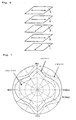
- the viewing angle characteristics of the liquid crystal display were evaluated by the naked eyes. Good and homogeneous images could be observed when an image was viewed from the vertical direction and when it was viewed from a polar angle of smaller than 80 degrees. Contrast curves obtained by simulation of the liquid crystal display are shown in Fig. 5.
- liquid crystal cell 2 film 3 of optically anisotropic substance (B5) prepared in Production Example 6, and film 4 of optically anisotropic substance (A5) prepared in Production Example 5 were laminated in this order in a manner such that the slow axis of liquid crystal cell 2 at voltage-non-imposition is perpendicular to the slow axis of optically anisotropic substance (B5) film 3, and the slow axis of optically anisotropic substance (B3) film 3 is perpendicular to the slow axis of optically anisotropic substance (A5) film 4, to give an optical multilayer body.
- retardation R 0 when light having wavelength of 550 nm was vertically incident was 192 nm
- R 40 when the light was incident at 40 degrees inclined from the normal was 199 nm in ⁇ direction and 184 nm in ⁇ direction
- R 0 /R 40 was 1.04 in ⁇ direction and 0.96 in ⁇ direction.
- An incident side polarizer 1 and a light emission side polarizer 5 were laminated together with the above-mentioned optical multilayer body in a manner such that the absorption axis of the incident side polarizer 1 is parallel to the slow axis of liquid crystal cell 2 at voltage-non-imposition, and the slow axis of optically anisotropic substance (A5) film 4 is parallel to the absorption axis of light emission side polarizer 5, to give a liquid crystal display having a multilayer structure as illustrated in Fig. 6.
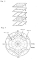
- the viewing angle characteristics of the liquid crystal display were evaluated by the naked eyes. Good and homogeneous images could be observed when an image was viewed from the vertical direction and when it was viewed from a polar angle of smaller than 80 degrees. Contrast curves obtained by simulation of the liquid crystal display are shown in Fig. 7.
- film 3 of optically anisotropic substance (B7) prepared in Production Example 8 film 4 of optically anisotropic substance (A7) prepared in Production Example 7, and liquid crystal cell 2 were laminated in this order in a manner such that the slow axis of optically anisotropic substance (B7) film 3 is perpendicular to the slow axis of optically anisotropic substance (A7) film 4, and the slow axis of optically anisotropic substance (A7) film 4 is perpendicular to the slow axis of liquid crystal cell 2 at voltage-non-imposition, to give an optical multilayer body.
- retardation R 0 when light having wavelength of 550 nm was vertically incident was 279 nm
- R 40 when the light was incident at 40 degrees inclined from the normal was 267 nm in ⁇ direction and 287 nm in ⁇ direction
- R 0 /R 40 was 0.96 in ⁇ direction and 1.03 in ⁇ direction.
- a light incident side polarizer 1 and a light emission side polarizer 5 were laminated together with the above-mentioned optical multilayer body in a manner such that the absorption axis of the light incident side polarizer 1 is perpendicular to the slow axis of optically anisotropic substance (B7) film 3, and the slow axis of liquid crystal cell 2 at voltage-non-imposition is parallel to the absorption axis of light emission side polarizer 5, to give a liquid crystal display having a multilayer structure as illustrated in Fig. 8.
- the viewing angle characteristics of the liquid crystal display were evaluated by the naked eyes. Good and homogeneous images could be observed when an image was viewed from the vertical direction and when it was viewed from a polar angle of smaller than 80 degrees. Contrast curves obtained by simulation of the liquid crystal display are shown in Fig. 9.
- liquid crystal cell 2 and film 3 of optically anisotropic substance (C1) prepared in Production Example 9 were laminated in a manner such that the slow axis of liquid crystal cell 2 at voltage-non-imposition is perpendicular to the slow axis of optically anisotropic substance (C1) film 3, to give an optical multilayer body.
- retardation R 0 when light having wavelength of 550 nm was vertically incident was 149 nm
- R 40 when the light was incident at 40 degrees inclined from the normal was 167 nm in ⁇ direction and 129 nm in ⁇ direction
- R 0 /R 40 was 1.12 in ⁇ direction and 0.87 in ⁇ direction.
- An incident side polarizer 1 and a light emission side polarizer 5 were laminated together with the above-mentioned optical multilayer body in a manner such that the absorption axis of the incident side polarizer 1 is perpendicular to the slow axis of liquid crystal cell 2 at voltage-non-imposition, and the slow axis of optically anisotropic substance (C1) film 3 is parallel to the absorption axis of light emission side polarizer 5, to give a liquid crystal display having a multilayer structure as illustrated in Fig. 10.
- the viewing angle characteristics of the liquid crystal display were evaluated by the naked eyes. Good images could be observed when an image was viewed from the vertical direction, but the quality at black display was poor and the contrast was low when it was viewed obliquely from an azimuth of 45 degrees. Contrast curves obtained by simulation of the liquid crystal display are shown in Fig. 11.
- film 3 of optically anisotropic substance (C1) prepared in Production Example 9 liquid crystal cell 2 and film 4 of optically anisotropic substance (C1) prepared in Production Example 9 were laminated in a manner such that the slow axis of optically anisotropic substance (C1) film 3 is perpendicular to the slow axis of liquid crystal cell 2 at voltage-non-imposition, and the slow axis of liquid crystal cell 2 at voltage-non-imposition is perpendicular to the slow axis of optically anisotropic substance (C1) film 4, to give an optical multilayer body.
- retardation R 0 when light having wavelength of 550 nm was vertically incident was 27 nm
- R 40 when the light was incident at 40 degrees inclined from the normal was 32 nm in ⁇ direction and 19 nm in ⁇ direction
- R 0 /R 40 was 1.19 in ⁇ direction and 0.70 in ⁇ direction.
- An incident side polarizer 1 and a light emission side polarizer 5 were laminated together with the above-mentioned optical multilayer body in a manner such that the absorption axis of the incident side polarizer 1 is parallel to the slow axis of optically anisotropic substance (C1) film 3, and the slow axis of optically anisotropic substance (C1) film 4 is perpendicular to the absorption axis of light emission side polarizer 5, to give a liquid crystal display having a multilayer structure as illustrated in Fig. 12.
- the viewing angle characteristics of the liquid crystal display were evaluated by the naked eyes. Good images could be observed when an image was viewed from the vertical direction, but the quality at black display was poor and the contrast was low when it was viewed obliquely from an azimuth of 45 degrees. Contrast curves obtained by simulation of the liquid crystal display are shown in Fig. 13.
- Abrasion resistance LRI layer HC layer Ex.1 1.36 1.62 A 0.6 A A Ex.2 1.36 1.62 A 0.6 A A Ex.3 1.36 1.62 A 0.6 A A Ex. 4 1.36 1.62 A 0.6 A A Co. Ex. 1 - - C 5.0 - - Co. Ex. 2 - - C 5.0 - - LRI layer: Low refractive index layer HC layer: Hard coat layer
- the liquid crystal displays described in Examples 1 to 4 exhibit good visibility (i.e., glare and mirroring are not observed), low refractive index, black color reflection, and good abrasion resistance.
- the liquid crystal displays described in Comparative Examples 1 and 2 exhibit poor visibility (i.e., glare and mirroring are observed), high refractive index, blue color reflection, and poor abrasion resistance.
- the liquid crystal display according to the present invention exhibits improved reflection prevention and abrasive resistance, and is characterized in that when an image on the display is viewed from an oblique direction, the deterioration in contrast can be prevented or minimized without substantial deterioration of image characteristics as viewed from a vertical direction, and well qualified images are manifested at black display for wide view angles, and homogeneous images with a high contrast are obtained.
- the liquid crystal display according to the present invention is especially suitable for a flat panel display with a large picture plane.
Landscapes
- Physics & Mathematics (AREA)
- Nonlinear Science (AREA)
- Mathematical Physics (AREA)
- Chemical & Material Sciences (AREA)
- Crystallography & Structural Chemistry (AREA)
- General Physics & Mathematics (AREA)
- Optics & Photonics (AREA)
- Liquid Crystal (AREA)
- Polarising Elements (AREA)
Applications Claiming Priority (2)
| Application Number | Priority Date | Filing Date | Title |
|---|---|---|---|
| JP2004280122 | 2004-09-27 | ||
| PCT/JP2005/017288 WO2006035635A1 (fr) | 2004-09-27 | 2005-09-20 | Affichage a cristaux liquides |
Publications (2)
| Publication Number | Publication Date |
|---|---|
| EP1798593A1 true EP1798593A1 (fr) | 2007-06-20 |
| EP1798593A4 EP1798593A4 (fr) | 2008-04-02 |
Family
ID=36118784
Family Applications (1)
| Application Number | Title | Priority Date | Filing Date |
|---|---|---|---|
| EP05785710A Withdrawn EP1798593A4 (fr) | 2004-09-27 | 2005-09-20 | Affichage a cristaux liquides |
Country Status (5)
| Country | Link |
|---|---|
| US (1) | US20070285599A1 (fr) |
| EP (1) | EP1798593A4 (fr) |
| JP (1) | JPWO2006035635A1 (fr) |
| KR (1) | KR20070059190A (fr) |
| WO (1) | WO2006035635A1 (fr) |
Cited By (1)
| Publication number | Priority date | Publication date | Assignee | Title |
|---|---|---|---|---|
| WO2006068331A1 (fr) | 2004-12-24 | 2006-06-29 | Matsushita Electric Works, Ltd. | Affichage a cristaux liquides |
Families Citing this family (13)
| Publication number | Priority date | Publication date | Assignee | Title |
|---|---|---|---|---|
| JP2011507009A (ja) * | 2007-12-04 | 2011-03-03 | エルジー・ケム・リミテッド | 視野角補償フィルム積層体及びこれを利用した面内切り替え液晶表示装置 |
| JP5210992B2 (ja) * | 2009-07-27 | 2013-06-12 | 日東電工株式会社 | 積層光学フィルムの製造方法 |
| CN103069330B (zh) * | 2010-08-23 | 2016-01-06 | 夏普株式会社 | 液晶显示面板 |
| FR2976680B1 (fr) * | 2011-06-14 | 2013-06-28 | Essilor Int | Procede de fabrication de lentilles |
| US8780301B2 (en) * | 2011-10-07 | 2014-07-15 | Japan Display West Inc. | Liquid crystal display device |
| US9933647B2 (en) | 2013-05-08 | 2018-04-03 | Empire Technology Development Llc | Display devices including oriented nucleic acid layers and methods of making and using the same |
| WO2015178447A1 (fr) * | 2014-05-23 | 2015-11-26 | Dic株式会社 | Dispositif d'affichage d'image, et matériau orienté mettant en œuvre celui-ci |
| US9829617B2 (en) * | 2014-11-10 | 2017-11-28 | Light Polymers Holding | Polymer-small molecule film or coating having reverse or flat dispersion of retardation |
| US9856172B2 (en) | 2015-08-25 | 2018-01-02 | Light Polymers Holding | Concrete formulation and methods of making |
| JP7056152B2 (ja) | 2015-12-17 | 2022-04-19 | 日本ゼオン株式会社 | 液晶表示装置 |
| US10962696B2 (en) | 2018-01-31 | 2021-03-30 | Light Polymers Holding | Coatable grey polarizer |
| US11370914B2 (en) | 2018-07-24 | 2022-06-28 | Light Polymers Holding | Methods of forming polymeric polarizers from lyotropic liquid crystals and polymeric polarizers formed thereby |
| US12072520B2 (en) | 2021-11-11 | 2024-08-27 | Light Polymers Holding | Linear polarizers and methods of forming a linear polarizer |
Family Cites Families (10)
| Publication number | Priority date | Publication date | Assignee | Title |
|---|---|---|---|---|
| JP3284002B2 (ja) * | 1993-11-22 | 2002-05-20 | 富士写真フイルム株式会社 | 楕円偏光板およびそれを用いた液晶表示装置 |
| JP3118208B2 (ja) * | 1996-05-15 | 2000-12-18 | 富士写真フイルム株式会社 | 液晶表示装置 |
| JPH1164601A (ja) * | 1997-08-11 | 1999-03-05 | Fuji Photo Film Co Ltd | 反射防止膜およびそれを配置した表示装置 |
| JP3204182B2 (ja) * | 1997-10-24 | 2001-09-04 | 日本電気株式会社 | 横電界方式の液晶表示装置 |
| JP4441971B2 (ja) * | 2000-02-28 | 2010-03-31 | ソニー株式会社 | 液晶表示素子 |
| US6770334B2 (en) * | 2000-03-29 | 2004-08-03 | Fuji Photo Film Co., Ltd. | Optically anisotropic sheet comprising aligned discotic liquid crystal molecules |
| JP3998897B2 (ja) * | 2000-08-11 | 2007-10-31 | セイコーエプソン株式会社 | 液晶表示装置 |
| JP2003149642A (ja) * | 2001-11-13 | 2003-05-21 | Matsushita Electric Works Ltd | 液晶用フロントライト |
| JP2004249495A (ja) * | 2003-02-18 | 2004-09-09 | Fuji Photo Film Co Ltd | 反射防止フィルム、偏光板及び画像表示装置 |
| JP4378972B2 (ja) * | 2003-02-25 | 2009-12-09 | パナソニック電工株式会社 | 反射防止膜、反射防止膜の製造方法、反射防止部材 |
-
2005
- 2005-09-20 US US11/663,838 patent/US20070285599A1/en not_active Abandoned
- 2005-09-20 EP EP05785710A patent/EP1798593A4/fr not_active Withdrawn
- 2005-09-20 WO PCT/JP2005/017288 patent/WO2006035635A1/fr not_active Ceased
- 2005-09-20 JP JP2006537687A patent/JPWO2006035635A1/ja not_active Withdrawn
- 2005-09-20 KR KR1020077009527A patent/KR20070059190A/ko not_active Withdrawn
Cited By (3)
| Publication number | Priority date | Publication date | Assignee | Title |
|---|---|---|---|---|
| WO2006068331A1 (fr) | 2004-12-24 | 2006-06-29 | Matsushita Electric Works, Ltd. | Affichage a cristaux liquides |
| EP1845406A4 (fr) * | 2004-12-24 | 2009-11-04 | Panasonic Elec Works Co Ltd | Affichage a cristaux liquides |
| US7964251B2 (en) | 2004-12-24 | 2011-06-21 | Panasonic Electric Works Co., Ltd. | Liquid crystal display device |
Also Published As
| Publication number | Publication date |
|---|---|
| KR20070059190A (ko) | 2007-06-11 |
| WO2006035635A1 (fr) | 2006-04-06 |
| JPWO2006035635A1 (ja) | 2008-05-15 |
| EP1798593A4 (fr) | 2008-04-02 |
| US20070285599A1 (en) | 2007-12-13 |
Similar Documents
| Publication | Publication Date | Title |
|---|---|---|
| US8223304B2 (en) | Liquid crystal display device | |
| EP1094340B1 (fr) | Film antiéblouissant et antiréfléchissant, polarisateur et dispositif d'affichage d'images | |
| JP3044681B2 (ja) | 液晶表示装置 | |
| JP4857124B2 (ja) | 液晶表示装置 | |
| CN115443424B (zh) | 光学层叠体、图像显示装置及玻璃复合体 | |
| TWI338151B (en) | Liquid crystal display device | |
| WO2008059721A1 (fr) | Plaque de polarisation elliptique et affichage à cristaux liquides à alignement vertical | |
| KR100717564B1 (ko) | 액정 표시 장치 | |
| TW200844509A (en) | Transparent protective film, optical compensation film, polarizing plate, and liquid crystal display device | |
| US20120169970A1 (en) | Surface film, polarizing plate and image display device | |
| US10481435B2 (en) | Horizontal alignment-type liquid crystal display device | |
| US20070285599A1 (en) | Liquid Crystal Display | |
| CN101371188A (zh) | 液晶显示装置 | |
| US7639330B2 (en) | Liquid crystal display device | |
| US7692747B2 (en) | In-plane switching mode liquid crystal display device having a biaxial optically anisotropic member | |
| JP3987569B1 (ja) | 液晶パネル、それを用いた液晶表示装置、および液晶パネルの製造方法 | |
| JP2003207630A (ja) | 楕円偏光板およびそれを用いた液晶表示装置 | |
| JP5857091B2 (ja) | 立体画像表示装置 | |
| TW201326990A (zh) | 液晶顯示裝置 | |
| KR100671402B1 (ko) | 네마틱 액정 코팅을 이용한 네가티브 보상필름 및 이를포함하는 광학 필름의 제조방법 | |
| WO2009028428A1 (fr) | Plaque de polarisation elliptique et dispositif d'affichage à cristaux liquides |
Legal Events
| Date | Code | Title | Description |
|---|---|---|---|
| PUAI | Public reference made under article 153(3) epc to a published international application that has entered the european phase |
Free format text: ORIGINAL CODE: 0009012 |
|
| 17P | Request for examination filed |
Effective date: 20070427 |
|
| AK | Designated contracting states |
Kind code of ref document: A1 Designated state(s): DE FR GB |
|
| RBV | Designated contracting states (corrected) |
Designated state(s): DE FR GB |
|
| DAX | Request for extension of the european patent (deleted) | ||
| A4 | Supplementary search report drawn up and despatched |
Effective date: 20080229 |
|
| STAA | Information on the status of an ep patent application or granted ep patent |
Free format text: STATUS: THE APPLICATION IS DEEMED TO BE WITHDRAWN |
|
| 18D | Application deemed to be withdrawn |
Effective date: 20080919 |