EP1798618A2 - Dispositif et procédé pour la mise automatique des interlocks entre des robots - Google Patents
Dispositif et procédé pour la mise automatique des interlocks entre des robots Download PDFInfo
- Publication number
- EP1798618A2 EP1798618A2 EP06024620A EP06024620A EP1798618A2 EP 1798618 A2 EP1798618 A2 EP 1798618A2 EP 06024620 A EP06024620 A EP 06024620A EP 06024620 A EP06024620 A EP 06024620A EP 1798618 A2 EP1798618 A2 EP 1798618A2
- Authority
- EP
- European Patent Office
- Prior art keywords
- robot
- interference area
- dimensional
- area
- robots
- Prior art date
- Legal status (The legal status is an assumption and is not a legal conclusion. Google has not performed a legal analysis and makes no representation as to the accuracy of the status listed.)
- Granted
Links
Images


Classifications
-
- B—PERFORMING OPERATIONS; TRANSPORTING
- B25—HAND TOOLS; PORTABLE POWER-DRIVEN TOOLS; MANIPULATORS
- B25J—MANIPULATORS; CHAMBERS PROVIDED WITH MANIPULATION DEVICES
- B25J9/00—Program-controlled manipulators
- B25J9/16—Program controls
- B25J9/1679—Program controls characterised by the tasks executed
- B25J9/1682—Dual arm manipulator; Coordination of several manipulators
-
- G—PHYSICS
- G05—CONTROLLING; REGULATING
- G05B—CONTROL OR REGULATING SYSTEMS IN GENERAL; FUNCTIONAL ELEMENTS OF SUCH SYSTEMS; MONITORING OR TESTING ARRANGEMENTS FOR SUCH SYSTEMS OR ELEMENTS
- G05B19/00—Program-control systems
- G05B19/02—Program-control systems electric
- G05B19/418—Total factory control, i.e. centrally controlling a plurality of machines, e.g. direct or distributed numerical control [DNC], flexible manufacturing systems [FMS], integrated manufacturing systems [IMS] or computer integrated manufacturing [CIM]
- G05B19/41815—Total factory control, i.e. centrally controlling a plurality of machines, e.g. direct or distributed numerical control [DNC], flexible manufacturing systems [FMS], integrated manufacturing systems [IMS] or computer integrated manufacturing [CIM] characterised by the cooperation between machine tools, manipulators and conveyor or other workpiece supply system, workcell
-
- G—PHYSICS
- G05—CONTROLLING; REGULATING
- G05B—CONTROL OR REGULATING SYSTEMS IN GENERAL; FUNCTIONAL ELEMENTS OF SUCH SYSTEMS; MONITORING OR TESTING ARRANGEMENTS FOR SUCH SYSTEMS OR ELEMENTS
- G05B2219/00—Program-control systems
- G05B2219/30—Nc systems
- G05B2219/39—Robotics, robotics to robotics hand
- G05B2219/39135—For multiple manipulators operating at same time, avoid collision
-
- G—PHYSICS
- G05—CONTROLLING; REGULATING
- G05B—CONTROL OR REGULATING SYSTEMS IN GENERAL; FUNCTIONAL ELEMENTS OF SUCH SYSTEMS; MONITORING OR TESTING ARRANGEMENTS FOR SUCH SYSTEMS OR ELEMENTS
- G05B2219/00—Program-control systems
- G05B2219/30—Nc systems
- G05B2219/40—Robotics, robotics mapping to robotics vision
- G05B2219/40317—For collision avoidance and detection
-
- Y—GENERAL TAGGING OF NEW TECHNOLOGICAL DEVELOPMENTS; GENERAL TAGGING OF CROSS-SECTIONAL TECHNOLOGIES SPANNING OVER SEVERAL SECTIONS OF THE IPC; TECHNICAL SUBJECTS COVERED BY FORMER USPC CROSS-REFERENCE ART COLLECTIONS [XRACs] AND DIGESTS
- Y02—TECHNOLOGIES OR APPLICATIONS FOR MITIGATION OR ADAPTATION AGAINST CLIMATE CHANGE
- Y02P—CLIMATE CHANGE MITIGATION TECHNOLOGIES IN THE PRODUCTION OR PROCESSING OF GOODS
- Y02P90/00—Enabling technologies with a potential contribution to greenhouse gas [GHG] emissions mitigation
- Y02P90/02—Total factory control, e.g. smart factories, flexible manufacturing systems [FMS] or integrated manufacturing systems [IMS]
Definitions
- the present invention relates to a device and a method for automatically setting an interlock so as to avoid interference between robots.
- Japanese Unexamined Patent Publication No. 10-3308 discloses a method for avoiding interference between a robot and external equipment.
- an interference area is predetermined and a signal is sent to one of the robot and the press machine, such that one cannot enter the interference area when the other is located in the area.
- a device for automatically setting an interlock between a plurality of robots, by editing a motion program of each robot comprising: an interference area setting section for setting an interference area between the robots, using a simulation result based on the motion program of each robot; and a program editing section for inserting a motion command and a communication command before and after a command for moving each robot through the interference area of the motion program, the motion command being configured to direct the position and the orientation of each robot when the robot enters or leaves the interference area, and the communication command being configured to inform a robot of entering and leaving the interference area of the other robot.
- the interference area setting section may have a first interference area calculating part, the first interference area calculating part being configured to calculate two-dimensional coordinates of a moving path of a farthest point of each robot based on the simulation result, a two-dimensional interference area based the two-dimensional coordinates of the moving path of each robot, and a first three-dimensional interference area formed by moving the two-dimensional interference area in the direction perpendicular to the two-dimensional interference area.
- the interference area setting section may further have a second interference area calculating part, the second interference area calculating part being configured to calculate a three-dimensional transit area of the moving path of each robot in the first interference area, by using a three-dimensional model of each robot, and a second three-dimensional interference area by checking interference between each three-dimensional transit area in the first three-dimensional interference area.
- a method for automatically setting an interlock between a plurality of robots, by editing a motion program of each robot comprising the steps of: setting an interference area between the robots, using a simulation result based on the motion program of each robot; and inserting a motion command and a communication command before and after a command for moving a robot through the interference area of the motion program, the motion command being configured to direct the position and the orientation of the robot when the robot enters or leaves the interference area, and the communication command being configured to inform the other robots of entering and leaving the interference area of one robot.
- the setting step may include a step of calculating two-dimensional coordinates of a moving path of a farthest point of each robot based on the simulation result, a two-dimensional interference area based the two-dimensional coordinates of the moving path of each robot, and a first three-dimensional interference area formed by moving the two-dimensional interference area in the direction perpendicular to the two-dimensional interference area.
- the setting step may further include the step of calculating a three-dimensional transit area of the moving path of each robot in the first interference area, by using a three-dimensional model of each robot, and a second three-dimensional interference area by checking interference between each three-dimensional transit area in the first three-dimensional interference area.
- FIG. 5 shows a preferred schematic constitution of an interlock setting device 1 of the invention.
- the interlock setting device 1 includes an interference area setting section 2 for setting an interference area between the robots, using a simulation result based on the motion program of each robot; and a program editing section 3 for inserting a motion command and a communication command before and after a command for moving a robot through the interference area of the motion program, the motion command being configured to direct the position and the orientation of the robot when the robot enters or leaves the interference area, and the communication command being configured to inform the other robots of entering and leaving the interference area of one robot.
- the interference area setting section 2 includes a first interference area calculating part 4 for determining a two-dimensional interference area and a first three-dimensional interference area as described below, and a second interference area calculating part 5 for determining a second three-dimensional interference area as described below.
- the actual interlock setting device may be included in a programming device for making a motion program and/or a teaching program for each robot, otherwise, may be arranged separately from the programming device.
- the interlock setting device for avoiding interference between two robots, i.e., a robot 10 and a robot 20, will be explained.
- the same concept may be applied to a case of three or more robots.
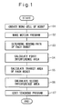
- Fig. 1 is a flowchart showing a procedure or a setting method executed by the interlock setting device of the invention.
- a work cell in which the robots 10 and 20 are arranged, is created (step S1 in Fig. 1).
- Fig. 2 shows the robot 10 only, as the robot 20 is similar to the robot 10.
- a point on the robot 10 which may be the farthest point from the origin 12 of the robot viewed in the two-dimensional coordinate, is set.
- an end point 16 of a tool 14 or a point on a link 18 may be the farthest point.
- the farthest point is the tool end point 16 in the case of Figs. 2a and 2b, on the other hand, the farthest point is the link 18 in the case of Fig. 2c.
- a motion program for each robot is made (step S2 in Fig. 1).
- the motion program is made by the conventional method based on the operation required for each robot.
- a simulation is executed off-line on a programming system, so as to determine the moving path of each robot (step S3 in Fig. 1).
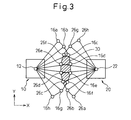
- Fig. 3 shows a result of this simulation.
- the robots 10 and 20 are schematically arranged on the same two-dimensional coordinate as that of Figs. 2a to 2c. In other words, only the origins 12 and the farthest points 16a to 16h of the robot 10, and only the origins 22 and the farthest points 26a to 26h of the robot 20 are indicated in Fig. 3.
- a plane of a two-dimensional area 30 (indicated by hatching lines in Fig. 3) is calculated and is referred to as an overlapping area between each area formed by the trajectory of the farthest points and the origin of each robot. Then, the two-dimensional area 30 is stored as a two-dimensional interference area (step S4 in Fig. 1).
- the two-dimensional interference area 30 is moved vertically or in the Z-direction so as to create a first three-dimensional interference area 32.
- the first three-dimensional interference area 32 is a whole series of points whose X, Y-coordinates are within the plane 30 and the Z-coordinate is arbitrary.
- the first three-dimensional interference area 32 roughly includes an area in which interference may occur when each robot is operated according to the motion program. In other words, interference cannot occur in an area outside of the first three-dimensional interference area 32.
- a correct three-dimensional transit area of each robot is calculated when each robot is operated according to the motion program (step S5 in Fig. 1).
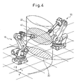
- the transit area of each robot may be calculated by using a predetermined three-dimensional CAD model of each robot as shown in Figs. 2a to 2c and 4.
- the correct transit area of each robot may be calculated by, first, calculating a correct occupying area of each robot and, second, calculating the summation of the occupying area of each robot at all points in the first three-dimensional interference area 32.
- a product (or an overlapping area) of two transit areas of the robots 10 and 20 in the first three-dimensional interference area 32 is calculated and stored as a second three-dimensional interference area 40 (step S6 in Fig. 1).
- the second three-dimensional interference area 40 as shown in Fig. 4, is calculated as a three-dimensional area occupying a part of the first three-dimensional interference area 32. It can be said that the second three-dimensional interference area 40 is an accurate area in which interference may occur when each robot is operated according to the motion program. As described above, as the first three-dimensional interference area 32 roughly including the accurate area has already been calculated, the second three-dimensional interference area 40 may be calculated in a relatively short time.
- the robot 20 There are some preferable ways to inform one robot (for example, the robot 20) of the presence of another robot (for example, the robot 10) in the second three-dimensional interference area 40.
- the positions and the orientations of the robots 10 and 20, immediately or a predetermined time before entering the second interference area 40, or in front of the second interference area 40 by a predetermined distance are calculated.
- the positions and the orientations of the robots 10 and 20, immediately or a predetermined time after leaving the second interference area 40, or at the rear of the second interference area 40 by a predetermined distance are calculated.
- Motion commands, for moving and orienting the robots to the calculated positions and orientations are inserted into the teaching program.
- a command such as an I/O command, for inform the robot 20 of entering and leaving the second interference area 40 of the robot 10, is inserted into the teaching program, whereby the robot 20 may wait before the above motion command, from when the robot 10 enters the second interference area 40 and to when the robot 10 leaves the same.
- the waiting time of the robot 20 may be minimized, resulting in that a suitable interlock may be set.
- step S7 in Fig. 1 based on only the first interference area 32 (i.e., steps S5 and S6 are omitted).
- the waiting time of the robot may be somewhat overestimated and the tact time of each robot may be extended accordingly.
- this case does not need the three-dimensional CAD models of the robots and the calculation using the same, the calculating time may be shortened.
- a huge memory area and a long calculation time are required, especially when a large number of robots are used.
- an interlock in an offline-programming system, may be automatically set based on an interference area between robots obtained by a simulation.
- This interference area may be determined by, first, calculating a rough first interference area above the two-dimensional plane and, second, calculating a second three-dimensional interference area within the first interference area. Therefore, an accurate interference area may be calculated in a short time.
- the collision between robots at an unexpected position may be avoided. Further, the unnecessarily long waiting time of the robot which may cause the long tact time may also be avoided.
- the interlock may be automatically set, a stable interlock which does not depends on the skill of an operator may be achieved and the workload on the operator may be reduced.
Landscapes
- Engineering & Computer Science (AREA)
- General Engineering & Computer Science (AREA)
- Manufacturing & Machinery (AREA)
- Quality & Reliability (AREA)
- Physics & Mathematics (AREA)
- General Physics & Mathematics (AREA)
- Automation & Control Theory (AREA)
- Robotics (AREA)
- Mechanical Engineering (AREA)
- Numerical Control (AREA)
- Manipulator (AREA)
Applications Claiming Priority (1)
| Application Number | Priority Date | Filing Date | Title |
|---|---|---|---|
| JP2005359001A JP4159577B2 (ja) | 2005-12-13 | 2005-12-13 | 複数のロボット間のインターロック自動設定装置及び自動設定方法 |
Publications (3)
| Publication Number | Publication Date |
|---|---|
| EP1798618A2 true EP1798618A2 (fr) | 2007-06-20 |
| EP1798618A3 EP1798618A3 (fr) | 2009-08-05 |
| EP1798618B1 EP1798618B1 (fr) | 2011-04-06 |
Family
ID=37865857
Family Applications (1)
| Application Number | Title | Priority Date | Filing Date |
|---|---|---|---|
| EP06024620A Active EP1798618B1 (fr) | 2005-12-13 | 2006-11-28 | Dispositif et procédé pour la mise automatique des verrouillages entre des robots |
Country Status (5)
| Country | Link |
|---|---|
| US (1) | US7937186B2 (fr) |
| EP (1) | EP1798618B1 (fr) |
| JP (1) | JP4159577B2 (fr) |
| CN (1) | CN100542754C (fr) |
| DE (1) | DE602006021122D1 (fr) |
Cited By (3)
| Publication number | Priority date | Publication date | Assignee | Title |
|---|---|---|---|---|
| DE102010032917A1 (de) * | 2010-07-30 | 2012-04-19 | Brötje-Automation GmbH | Verfahren zur Offline-Programmierung eines NC-gesteuerten Manipulators |
| EP3195990A1 (fr) * | 2016-01-25 | 2017-07-26 | Canon Kabushiki Kaisha | Procédé de génération de trajectoire de robot, appareil de génération de trajectoire de robot, procédé de fabrication de produit, support d'enregistrement, programme et système de robot |
| US12030187B2 (en) | 2018-07-17 | 2024-07-09 | Fanuc Corporation | Robot system |
Families Citing this family (49)
| Publication number | Priority date | Publication date | Assignee | Title |
|---|---|---|---|---|
| JP4844453B2 (ja) * | 2007-04-09 | 2011-12-28 | 株式会社デンソーウェーブ | ロボットの教示装置及び教示方法 |
| US9144904B2 (en) * | 2008-05-21 | 2015-09-29 | Fanuc Robotics America Corporation | Method and system for automatically preventing deadlock in multi-robot systems |
| JP5155144B2 (ja) * | 2008-12-26 | 2013-02-27 | ファナック株式会社 | ロボットの動作許容領域の自動設定装置 |
| JP5381208B2 (ja) * | 2009-03-23 | 2014-01-08 | 富士通株式会社 | 進入禁止空間分析プログラム、進入禁止空間分析装置、および進入禁止空間分析方法 |
| JP5653073B2 (ja) * | 2010-05-19 | 2015-01-14 | キヤノン株式会社 | ロボットセル装置及び生産システム |
| DE102012103830B4 (de) | 2011-05-05 | 2022-05-25 | Fanuc Robotics America Corp. | Verfahren und computerlesbare Medien zur automatischen Verbindung von gegenseitiger Blockierung in Mehrfachrobotersytemen |
| ITTO20110994A1 (it) * | 2011-10-31 | 2013-05-01 | Comau Spa | Metodo per il controllo di almeno due robot aventi rispettivi spazi di lavoro includenti almeno una regione in comune |
| KR101865237B1 (ko) * | 2012-01-26 | 2018-06-07 | 두산공작기계 주식회사 | 공작기계용 조작반 아암의 안전 제어방법 |
| US9517556B2 (en) * | 2012-06-29 | 2016-12-13 | Mitsubishi Electric Corporation | Robot control apparatus and robot control method |
| US9870611B2 (en) * | 2012-11-22 | 2018-01-16 | Yuyama Mfg. Co., Ltd. | Drug inspection device |
| KR101781709B1 (ko) * | 2013-02-06 | 2017-10-23 | 미쓰비시덴키 가부시키가이샤 | 간섭 체크 장치 |
| JP5768829B2 (ja) | 2013-03-15 | 2015-08-26 | 株式会社安川電機 | ロボットシステム、ロボット制御方法及び被加工物の製造方法 |
| JP5877867B2 (ja) * | 2014-04-25 | 2016-03-08 | ファナック株式会社 | 複数台のロボットのシミュレーション装置 |
| US9283678B2 (en) * | 2014-07-16 | 2016-03-15 | Google Inc. | Virtual safety cages for robotic devices |
| US10073434B1 (en) * | 2014-07-25 | 2018-09-11 | Jonathan Marc Hollander | Manufacturing systems and methods with multiple independent toolheads |
| JP6026484B2 (ja) * | 2014-10-31 | 2016-11-16 | ファナック株式会社 | 工作機械の周辺機器の自立制御を可能とするシステム |
| JP6735746B2 (ja) * | 2014-11-13 | 2020-08-05 | シーメンス アクチエンゲゼルシヤフトSiemens Aktiengesellschaft | 製品に生産動作を実行するための生産モジュール |
| JP6411964B2 (ja) * | 2015-07-27 | 2018-10-24 | ファナック株式会社 | 工作機械とロボットのリアルタイム干渉確認システム |
| JP2017134722A (ja) * | 2016-01-29 | 2017-08-03 | ファナック株式会社 | 共通の言語仕様のプログラムにて複数の種類の製造装置を駆動する製造システム |
| JP6392817B2 (ja) * | 2016-08-04 | 2018-09-19 | ファナック株式会社 | シミュレーション装置 |
| JP2018047509A (ja) * | 2016-09-20 | 2018-03-29 | ファナック株式会社 | ロボットシミュレーション装置 |
| CN106393112B (zh) * | 2016-11-15 | 2019-02-19 | 上海燊星机器人自动化科技有限公司 | 一种多机器人焊接方法及系统 |
| CN106363635B (zh) * | 2016-12-01 | 2018-08-31 | 广汽本田汽车有限公司 | 一种机器人运行仿真校准方法及装置 |
| JP6457469B2 (ja) * | 2016-12-08 | 2019-01-23 | ファナック株式会社 | 移動ロボットの干渉領域設定装置 |
| JP6484213B2 (ja) * | 2016-12-09 | 2019-03-13 | ファナック株式会社 | 複数のロボットを含むロボットシステム、ロボット制御装置、及びロボット制御方法 |
| JP6567101B2 (ja) * | 2017-03-06 | 2019-08-28 | キヤノン株式会社 | 教示方法、ロボットの動作方法、プログラム、記憶媒体、教示装置 |
| US10919153B2 (en) | 2017-03-06 | 2021-02-16 | Canon Kabushiki Kaisha | Teaching method for teaching operations to a plurality of robots and teaching system used therefor |
| DE102017213651A1 (de) * | 2017-08-07 | 2019-02-07 | Robert Bosch Gmbh | Handhabungseinrichtung mit einem Roboter sowie Verfahren und Computerprogramm |
| JP6745047B2 (ja) * | 2017-10-03 | 2020-08-26 | 株式会社安川電機 | 蓋閉めシステム及び蓋閉め方法 |
| CN108032333B (zh) * | 2017-10-30 | 2020-06-09 | 广州明珞汽车装备有限公司 | 可批量自动检查机器人仿真姿态的方法 |
| CN108044624A (zh) * | 2017-12-11 | 2018-05-18 | 上海信耀电子有限公司 | 一种基于powerlink总线的机器人控制系统 |
| AT16425U1 (de) * | 2017-12-14 | 2019-08-15 | Wittmann Kunststoffgeraete | Verfahren zur Validierung von programmierten Ablaufsequenzen oder |
| US10676022B2 (en) | 2017-12-27 | 2020-06-09 | X Development Llc | Visually indicating vehicle caution regions |
| CN108326859A (zh) * | 2018-05-07 | 2018-07-27 | 广东工业大学 | 一种有效避免机械臂在工作过程中发生干涉的方法 |
| CN109159118B (zh) * | 2018-08-29 | 2020-10-27 | 苏州精濑光电有限公司 | 干涉机构交叉作业防撞方法及装置 |
| JP6925599B2 (ja) * | 2018-09-04 | 2021-08-25 | 株式会社ゆめいど | シミュレーション方法及びシミュレーション装置 |
| CN111727414B (zh) * | 2018-12-27 | 2023-09-15 | 配天机器人技术有限公司 | 机器人控制方法、控制系统、机器人和存储装置 |
| CN109571939B (zh) * | 2019-01-29 | 2020-07-17 | 浙江大学 | 一种多机器人协同三维打印方法 |
| US20210187746A1 (en) * | 2019-12-23 | 2021-06-24 | X Development Llc | Task planning accounting for occlusion of sensor observations |
| JP7625395B2 (ja) * | 2020-01-31 | 2025-02-03 | キヤノン株式会社 | 情報処理装置、情報処理方法、生産システム、物品の製造方法、プログラム、および記録媒体 |
| US11656753B2 (en) | 2020-01-31 | 2023-05-23 | Canon Kabushiki Kaisha | Information processing device and method displaying at least two apparatuses for virtually checking interference |
| JP7484254B2 (ja) | 2020-03-13 | 2024-05-16 | オムロン株式会社 | 干渉判定装置、方法、及びプログラム |
| TWI763453B (zh) * | 2021-04-21 | 2022-05-01 | 所羅門股份有限公司 | 取物設備控制方法及系統與自動取物系統 |
| US20230182299A1 (en) * | 2021-12-14 | 2023-06-15 | Fanuc Corporation | Online auto-interlock strategy |
| CN114378840B (zh) * | 2021-12-20 | 2024-06-14 | 西安北方华创微电子装备有限公司 | 半导体工艺设备中传输系统的控制方法和半导体工艺设备 |
| CN114924529B (zh) * | 2022-06-20 | 2024-06-18 | 九众九机器人有限公司 | 一种机器人配对控制方法、装置、电子设备及存储介质 |
| US20240142985A1 (en) * | 2022-10-28 | 2024-05-02 | Zebra Technologies Corporation | De-centralized traffic-aware navigational planning for mobile robots |
| KR20240119805A (ko) * | 2023-01-30 | 2024-08-06 | 주식회사 마키나락스 | 복수의 작업 수행 로봇들 간 충돌을 방지하기 위한 방법 |
| WO2025121196A1 (fr) * | 2023-12-07 | 2025-06-12 | 日本電気株式会社 | Dispositif de planification de mouvement, procédé de mise à jour d'informations et programme |
Family Cites Families (14)
| Publication number | Priority date | Publication date | Assignee | Title |
|---|---|---|---|---|
| JPH07107648B2 (ja) * | 1987-09-09 | 1995-11-15 | インターナシヨナル・ビジネス・マシーンズ・コーポレーシヨン | 物体間衝突検出装置 |
| JPH08381B2 (ja) * | 1989-07-27 | 1996-01-10 | 株式会社不二越 | 産業用ロボットシステム及びその制御方法 |
| JPH0553634A (ja) * | 1991-08-29 | 1993-03-05 | Matsushita Electric Ind Co Ltd | 複腕干渉回避システム |
| JP2964837B2 (ja) | 1993-06-28 | 1999-10-18 | 日産自動車株式会社 | ロボットのインターロック信号設定方法 |
| JPH103308A (ja) | 1996-06-18 | 1998-01-06 | Fanuc Ltd | 産業用ロボットの干渉回避方法 |
| JPH10264058A (ja) | 1997-03-21 | 1998-10-06 | Nissan Motor Co Ltd | ロボット干渉域設定プログラム作成方法 |
| JPH11134017A (ja) * | 1997-10-27 | 1999-05-21 | Honda Motor Co Ltd | オフラインティーチング方法 |
| JPH11347984A (ja) | 1998-06-02 | 1999-12-21 | Nissan Motor Co Ltd | ロボット制御装置 |
| JP4228387B2 (ja) | 2001-10-25 | 2009-02-25 | 株式会社安川電機 | 複数ロボットの作業教示方法および作業教示装置 |
| JP3975959B2 (ja) * | 2003-04-23 | 2007-09-12 | トヨタ自動車株式会社 | ロボット動作規制方法とその装置およびそれを備えたロボット |
| JP2005081445A (ja) * | 2003-09-04 | 2005-03-31 | Fanuc Ltd | ロボットの干渉領域確認装置 |
| DE102004027944B4 (de) * | 2004-06-08 | 2012-02-16 | Kuka Laboratories Gmbh | Verfahren zum Schützen eines Roboters gegen Kollisionen |
| ES2306161T3 (es) * | 2004-06-15 | 2008-11-01 | Abb Ab | Metodo y sistema para la programacion fuera de linea de multiples robots interactuantes. |
| JP2007144524A (ja) * | 2005-11-24 | 2007-06-14 | Denso Wave Inc | ロボットの干渉回避方法およびロボット |
-
2005
- 2005-12-13 JP JP2005359001A patent/JP4159577B2/ja not_active Expired - Fee Related
-
2006
- 2006-11-28 DE DE602006021122T patent/DE602006021122D1/de active Active
- 2006-11-28 EP EP06024620A patent/EP1798618B1/fr active Active
- 2006-12-01 CN CNB2006101633647A patent/CN100542754C/zh active Active
- 2006-12-07 US US11/635,028 patent/US7937186B2/en active Active
Cited By (4)
| Publication number | Priority date | Publication date | Assignee | Title |
|---|---|---|---|---|
| DE102010032917A1 (de) * | 2010-07-30 | 2012-04-19 | Brötje-Automation GmbH | Verfahren zur Offline-Programmierung eines NC-gesteuerten Manipulators |
| EP3195990A1 (fr) * | 2016-01-25 | 2017-07-26 | Canon Kabushiki Kaisha | Procédé de génération de trajectoire de robot, appareil de génération de trajectoire de robot, procédé de fabrication de produit, support d'enregistrement, programme et système de robot |
| US10207406B2 (en) | 2016-01-25 | 2019-02-19 | Canon Kabushiki Kaisha | Robot trajectory generation method, robot trajectory generation apparatus, product fabrication method, recording medium, program, and robot system |
| US12030187B2 (en) | 2018-07-17 | 2024-07-09 | Fanuc Corporation | Robot system |
Also Published As
| Publication number | Publication date |
|---|---|
| JP2007164417A (ja) | 2007-06-28 |
| JP4159577B2 (ja) | 2008-10-01 |
| CN1982001A (zh) | 2007-06-20 |
| CN100542754C (zh) | 2009-09-23 |
| DE602006021122D1 (de) | 2011-05-19 |
| EP1798618A3 (fr) | 2009-08-05 |
| EP1798618B1 (fr) | 2011-04-06 |
| US20070150093A1 (en) | 2007-06-28 |
| US7937186B2 (en) | 2011-05-03 |
Similar Documents
| Publication | Publication Date | Title |
|---|---|---|
| US7937186B2 (en) | Device and method for automatically setting interlock between robots | |
| US9902067B2 (en) | Offline robot programming device | |
| EP1510894B1 (fr) | Appareil pour corriger une position d'un programme robot | |
| CN100561491C (zh) | 自动路径学习的方法和设备 | |
| US7376488B2 (en) | Taught position modification device | |
| US20060069466A1 (en) | Method for controlling trajectory of robot | |
| JP3732494B2 (ja) | シミュレーション装置 | |
| US8315738B2 (en) | Multi-arm robot system interference check via three dimensional automatic zones | |
| EP3566822A1 (fr) | Procédé de planification de trajectoire point-à-point dans l'espace d'articulations de robots | |
| US7904201B2 (en) | Robot programming device | |
| EP2418555B1 (fr) | Procédé de programmation hors ligne d'un manipulateur à commande NC | |
| EP1700667A1 (fr) | Appareil et méthode d'apprentissage pour le soudage au laser | |
| US20060149421A1 (en) | Robot controller | |
| US8560112B2 (en) | Numerical controller with function to correct movement path of machining program | |
| US20070073444A1 (en) | Offline teaching apparatus for robot | |
| US5341458A (en) | Method of and system for generating teaching data for robots | |
| US20230099602A1 (en) | Device control based on execution command and updated environment information | |
| CN112041128B (zh) | 机器人的教导方法和机器人的教导系统 | |
| JP4904731B2 (ja) | 工作機械の干渉チェック装置 | |
| US12377543B2 (en) | Path planning during execution of robot control | |
| EP4091776B1 (fr) | Dispositif de génération de programme, procédé de génération de programme et programme de génération | |
| CN109789552B (zh) | 工件处理系统 | |
| CN107199561B (zh) | 机器人控制装置和机器人程序生成装置 | |
| JP3040906B2 (ja) | ロボットの動作時間評価方法および装置 | |
| CN118331170B (zh) | 轨迹分析系统及方法 |
Legal Events
| Date | Code | Title | Description |
|---|---|---|---|
| PUAI | Public reference made under article 153(3) epc to a published international application that has entered the european phase |
Free format text: ORIGINAL CODE: 0009012 |
|
| AK | Designated contracting states |
Kind code of ref document: A2 Designated state(s): AT BE BG CH CY CZ DE DK EE ES FI FR GB GR HU IE IS IT LI LT LU LV MC NL PL PT RO SE SI SK TR |
|
| AX | Request for extension of the european patent |
Extension state: AL BA HR MK YU |
|
| PUAL | Search report despatched |
Free format text: ORIGINAL CODE: 0009013 |
|
| AK | Designated contracting states |
Kind code of ref document: A3 Designated state(s): AT BE BG CH CY CZ DE DK EE ES FI FR GB GR HU IE IS IT LI LT LU LV MC NL PL PT RO SE SI SK TR |
|
| AX | Request for extension of the european patent |
Extension state: AL BA HR MK RS |
|
| 17P | Request for examination filed |
Effective date: 20091209 |
|
| AKX | Designation fees paid |
Designated state(s): DE |
|
| RIC1 | Information provided on ipc code assigned before grant |
Ipc: G05B 19/418 20060101AFI20100903BHEP |
|
| GRAP | Despatch of communication of intention to grant a patent |
Free format text: ORIGINAL CODE: EPIDOSNIGR1 |
|
| RIN1 | Information on inventor provided before grant (corrected) |
Inventor name: NAGATSUKA, YOSHIHARU Inventor name: TAKEDA, TOSHIYA |
|
| RAP1 | Party data changed (applicant data changed or rights of an application transferred) |
Owner name: FANUC CORPORATION |
|
| GRAS | Grant fee paid |
Free format text: ORIGINAL CODE: EPIDOSNIGR3 |
|
| GRAA | (expected) grant |
Free format text: ORIGINAL CODE: 0009210 |
|
| AK | Designated contracting states |
Kind code of ref document: B1 Designated state(s): DE |
|
| REF | Corresponds to: |
Ref document number: 602006021122 Country of ref document: DE Date of ref document: 20110519 Kind code of ref document: P |
|
| REG | Reference to a national code |
Ref country code: DE Ref legal event code: R096 Ref document number: 602006021122 Country of ref document: DE Effective date: 20110519 |
|
| PLBE | No opposition filed within time limit |
Free format text: ORIGINAL CODE: 0009261 |
|
| STAA | Information on the status of an ep patent application or granted ep patent |
Free format text: STATUS: NO OPPOSITION FILED WITHIN TIME LIMIT |
|
| 26N | No opposition filed |
Effective date: 20120110 |
|
| REG | Reference to a national code |
Ref country code: DE Ref legal event code: R097 Ref document number: 602006021122 Country of ref document: DE Effective date: 20120110 |
|
| PGFP | Annual fee paid to national office [announced via postgrant information from national office to epo] |
Ref country code: DE Payment date: 20241022 Year of fee payment: 19 |