EP1798754A2 - Lampe fluorescente ayant une couche protectrice, et luminaire l'utilisant - Google Patents
Lampe fluorescente ayant une couche protectrice, et luminaire l'utilisant Download PDFInfo
- Publication number
- EP1798754A2 EP1798754A2 EP06256403A EP06256403A EP1798754A2 EP 1798754 A2 EP1798754 A2 EP 1798754A2 EP 06256403 A EP06256403 A EP 06256403A EP 06256403 A EP06256403 A EP 06256403A EP 1798754 A2 EP1798754 A2 EP 1798754A2
- Authority
- EP
- European Patent Office
- Prior art keywords
- fine particles
- sio
- glass tube
- protective film
- fluorescent lamp
- Prior art date
- Legal status (The legal status is an assumption and is not a legal conclusion. Google has not performed a legal analysis and makes no representation as to the accuracy of the status listed.)
- Withdrawn
Links
Images






Classifications
-
- H—ELECTRICITY
- H01—ELECTRIC ELEMENTS
- H01J—ELECTRIC DISCHARGE TUBES OR DISCHARGE LAMPS
- H01J61/00—Gas-discharge or vapour-discharge lamps
- H01J61/02—Details
- H01J61/30—Vessels; Containers
- H01J61/35—Vessels; Containers provided with coatings on the walls thereof; Selection of materials for the coatings
-
- H—ELECTRICITY
- H01—ELECTRIC ELEMENTS
- H01J—ELECTRIC DISCHARGE TUBES OR DISCHARGE LAMPS
- H01J61/00—Gas-discharge or vapour-discharge lamps
- H01J61/70—Lamps with low-pressure unconstricted discharge having a cold pressure < 400 Torr
- H01J61/72—Lamps with low-pressure unconstricted discharge having a cold pressure < 400 Torr having a main light-emitting filling of easily vaporisable metal vapour, e.g. mercury
Definitions
- This invention relates to a fluorescent lamp and to a lighting fixture wherein this fluorescent lamp is employed.
- a fluorescent lamp generally emits light according to the following mechanism. First of all, a mercury vapor sealed into a glass tube is exited by an electric discharge to generate ultraviolet rays. The ultraviolet rays thus generated are converted into visible rays using a phosphor layer which is coated on the inner surface of the glass tube, thus enabling the visible rays to be emitted from the glass tube.
- the lighting life of a fluorescent lamp can be generally classified into two types.
- One of the types is the life that depends on the disconnection of electrodes or on the exhaustion of thermoelectron-emitting substance (emitter) coated on the electrodes.
- the other is the life that depends on the coloring or darkening of the surface of the glass tube or phosphor or on the lowering of luminous flux due to the deterioration with time of the phosphor itself.
- the limit of life due to lowering of luminous flux is greatly influenced by the coloring or darkening of the surface of the glass tube.
- the coloring or darkening of the glass tube is assumed to be caused by the following phenomena. Namely, they include, for example, the generation of amalgam through a reaction between the mercury sealed into the fluorescent lamp and alkali components contained in the glass tube, the generation of mercury oxide through a reaction between the impurity gases entrapped in the glass tube and the mercury sealed into the glass tube, the penetration of mercury into the glass tube, and the solarization of the glass tube due to ultraviolet rays.
- a protective film comprising, as a major component, metal oxide fine particles at an interface between the inner surface of the glass tube and the phosphor layer.
- this protective film it is possible, with the provision of this protective film, to suppress the reaction between the glass tube and mercury or the phosphor layer. As a result, the coloring or darkening of the glass tube can be inhibited from being generated, thus making it possible to inhibit the lowering of luminous flux at an early stage. Further, due to this protective film, the quantity of mercury to be reacted with other substances existing inside the fluorescent lamp during the lightening time can be minimized, thus also realizing the effects that the consumption of mercury can be minimized. Therefore, it is also possible to reduce the quantity of mercury to be sealed into the glass tube to the minimum.
- fine particles of metal oxide such as. Al 2 O 3 and SiO 2 are known useful.
- SiO 2 is effective in absorbing ultraviolet rays and in preventing the implantation of mercury into the glass tube, it is impossible to prevent the darkening of the glass tube due to the lightening of the lamp from being prominently caused to occur.
- Al 2 O 3 is extensively employed in recent years as a material for forming the protective film.
- SiO 2 has possibilities of exhibiting advantageous properties compared to Al 2 O 3 . For example, it is suggested that when SiO 2 is inactivated, function of adsorbing impurity gases is degraded. Up to the present, various proposals have been made with a view to improve the flux life of the fluorescent lamp where a protective film comprising SiO 2 is employed.
- JA-A 2000-113856 describes a method of improving the flux life of the fluorescent lamp wherein the volume fraction of metal oxide particles such as SiO 2 and Al 2 O 3 and the magnitude of electrification are optimized in order to achieve the improvement.
- this method it is impossible to sufficiently improve the limit of life resulting from the lowering of luminous flux.
- the formation of mercury oxide through a reaction of residual hydroxyl group or carbon dioxide gas left in the fluorescent lamp with mercury causes the darkening. No one has however succeeded as yet to find techniques to effectively remove these residual hydroxyl group or carbon dioxide gas.
- the present invention has been made in view of the above problems and hence an object of the present invention is to provide a fluorescent lamp which is capable of inhibiting impurities which may become a cause for the generation of darkening from being entrapped and left in the glass tube, thereby making it possible to improve the luminous flux life thereof.
- a further object of the present invention is to provide a lighting fixture wherein this fluorescent lamp is utilized.
- the fluorescent lamp according to the present invention comprises a glass tube filled therein with an electric discharging medium, a protective film formed on an inner surface of the glass tube and comprising, as a major component, SiO 2 fine particles, a phosphor layer formed on an upper surface of the protective film, and electrode means attached to the glass tube, wherein the protective film is provided with the following characteristics.
- the SiO 2 fine particles constituting the protective film are selected from those exhibiting 0.3 or less at a temperature of 600°C in integrated value of absorbance spectrum of hydroxyl group absorption band in wave number ranging from 2500 to 3800 cm -1 as measured by infrared spectroscopy on the assumption that the integrated value of absorbance spectrum of hydroxyl group absorption band at a temperature of 100°C is 1.
- the SiO 2 fine particles constituting the protective film are selected from those containing carbon at a content ranging from 0.09% to 0.3% by mass.
- the SiO 2 fine particles constituting the protective film are selected from those exhibiting a spectrum having peaks at a wave number ranging from 590 to 610 cm -1 and at a wave number ranging from 490 to 500 cm -1 as measured by laser Raman spectroscopy and at a temperature of 700°C.
- the fluorescent lamp according to the present invention can be applied to a lamp of any optional configuration such as a straight type, a circular type, a U-shaped type, a W-shaped type, a bended type where a plurality of straight tubes are angularly connected with each other, or a plate type.
- the electrode means of the fluorescent lamp of the present invention may be a hot cathode type electrode where a filament coil is employed, or a cold cathode type electrode. Since the electrode means is only required to be such that it is capable of generating discharge in the glass tube, the electrode means may be an outer electrode for instance.
- the present invention is applicable not only to the ordinary fluorescent lamp but also to a rapid start type fluorescent lamp. Namely, the present invention is applicable to a fluorescent lamp wherein a transparent conductive film is disposed inside the tube, and a protective film and a phosphor layer are successively deposited on the surface of the conductive film which faces the air-tight space of the tube.
- a light-reflecting film may be interposed between the protective film and the phosphor film or between the protective film and the inner surface of the glass tube.
- the present inventors have taken,notice of the hydroxyl group on the surfaces of metal oxide particles to be employed for forming the protective film and have made extensive studies on this hydroxyl group. More specifically, the present inventors have made investigations to select metal oxide fine particles which easily dissociate hydroxyl group therefrom as they are heated up to a predetermined temperature. As a result, it has been found that fine particles which are capable of dissociating a definite quantity of the hydroxyl group adsorbed on the surfaces of the fine particles as they are heated to a predetermined temperature are useful. When the protective film is formed using such fine particles, it is possible to minimize the hydroxyl group left inside the fluorescent lamp, thus making it possible to suppress the generation of mercury oxide. As a result, it is possible to prolong the life time of the fluorescent lamp that might have been caused due to the lowering of luminous flux. The present invention has been made based on these findings.
- the measurement based on infrared spectroscopy can be performed by a Fourier transform infrared (FT-IR) spectrometer.
- FT-IR Fourier transform infrared
- the principle of this measurement is as follows. First of all, infrared ray wherein wave number continuously changes is irradiated from the FT-IR and to pass through a predetermined sample. The infrared ray that has passed through the sample is then measured and analyzed, thus obtaining a spectrum of wave number vs absorbency.
- the absorbency spectrum to be analyzed is confined within the range of 2500 to 3800 cm -1 in wave number. This range of wave number is considered to indicate the absorption band of hydroxyl group. As the absorbency of this wave number zone becomes higher, the quantity of adsorption of hydroxyl group will be increased.
- the measurement is conducted in vacuum while changing the temperature of sample from ordinary temperature to about 700°C.
- the integrated value at 100°C it is intended to mean an integrated value to be obtained through the integration of the wave number vs absorbency spectrums in the range of a wave number of 2500 to 3800 cm -1 that can be obtained from the infrared spectrometry which is performed in a reduced pressure of about 400 Pa while keeping the temperature of a sample at 100°C.
- the integrated value at 600°C can be determined from an integrated value of the wave number vs absorbency spectrums that can be calculated in the same manner as described above and obtained when the sample is increased in temperature up to 600°C and brought into a stable state while keeping the degree of vacuum.
- the sample to be used in this measurement is once exposed to air atmosphere of ordinary temperature to allow hydroxyl group to adsorb onto the sample prior to the installation of the sample in the infrared spectrometer.
- the resultant fluorescent lamp is capable of improving luminous flux maintenance factor as compared with the conventional fluorescent lamp where Al 2 O 3 fine particles are employed as a raw material for forming the protective film.
- the content of carbon depends is correlated with the luminous flux maintenance factor.
- the content of carbon should preferably be 0.09% or more.
- the content of carbon is regulated in this manner, the hydroxyl group to be adsorbed onto the SiO 2 fine particles can be minimized as compared with the conventional SiO 2 fine particles, thereby making it possible to enhance the luminous flux maintenance factor.
- problems such as the deterioration in transmittance of light generates due to the precipitation of carbon, thus rendering the protective film unsuitable for use in the fluorescent lamp.
- the fluorescent lamp wherein the protective film thereof is formed by SiO 2 fine particles having a carbon content ranging from 0.09% to 0.3% is capable of enhancing the luminous flux maintenance factor as compared with the fluorescent lamp wherein the protective film thereof is formed by the conventional SiO 2 fine particles.
- SiO 2 fine particles change the structure thereof in such a way that a broad spectrum having a wave number ranging from 200 to 500 cm -1 indicating an amorphous structure is disappeared and peaks are created at a wave number of about 494 cm- 1 representing a peak of a four-membered ring and at a wave number of about 606 cm -1 representing a peak of a three-membered ring.
- These changes may be assumably attributed to the fact that the structures of three-membered ring and four-membered ring are smaller in structure as compared with many-membered ring and with the crystal structure of SiO 2 , thereby enabling hydroxyl group to easily dissociate from SiO 2 fine particles.
- the SiO 2 fine particles constituting the protective film according to the present invention should preferably be created by the physical vapor synthesis (PVS) method.
- PVS physical vapor synthesis
- This PVS method is a method of creating the fine particles of oxide through a process wherein a raw material such as silicon and metals is vaporized through the application of thermal energy thereto and then allowed to take place oxidation reaction in an oxygen-containing atmosphere, thus creating the fine particles of oxide.
- a high-temperature hydrolysis method is generally employed, wherein silicon tetrachloride, oxygen and hydrogen are concurrently reacted with each other to manufacture SiO 2 .
- the SiO 2 fine particles that have been manufactured according to the conventional method contain a minute amount of hydrogen chloride (HCl).
- the SiO 2 fine particles that have been manufactured according to the PVS method are free from HCl.
- the present inventors found a fact that SiO 2 is less liable to adsorb CO, CO 2 gases than Al 2 O 3 . Therefore, a protective film comprising SiO 2 seems not to liable coloring due to CO, CO 2 gases than a protective film comprising Al 2 O 3 . Moreover, it was conformed that SiO 2 fine particles prepared by PVS method can be hardly adsorb CO, CO 2 gases.
- the SiO 2 fine particles which are also employed in the formation of the protective film.
- the glass tube of the fluorescent lamp of the present invention can be formed from glass having a thermal expansion coefficient ⁇ ranging from 85 to 105.
- the electric discharging medium should preferably be filled into the glass tube after evacuating the glass tube subsequent to heating of the glass tube at a temperature ranging from 500 to 650°C while maintaining the inner pressure of the glass tube.
- the impurity gas being adsorbed onto the inner wall of the glass tube can be more effectively removed.
- the quantity of impurity gas left in the glass tube after the evacuation thereof can be minimized.
- the soft glass having a thermal expansion coefficient ⁇ ranging from 85 to 105 and constituting the glass tube is relatively low in softening point, the glass tube may be collapsed by the pressure of atmospheric pressure if the temperature of the glass tube is increased 500°C or more while continuing the evacuation of the glass tube.
- the temperature of the glass tube in the step of exhausting the impurity gas should more preferably be confined to the range of 550 to 650°C, most preferably the range of 600 to 650°C.
- a light-reflecting film may be interposed at least a part of the interface between the protective film and the phosphor layer.
- the light-reflecting film is enabled to reflect most of the light having a visible wavelength range (about 380 to about 780 nm) and also is capable of permitting part of the visible rays to pass therethrough.
- the light-reflecting film may be formed by at least one kind of fine particles of material selected from strontium pyrophosphate, calcium pyrophosphate, titanium oxide and aluminum oxide (alumina). In addition to the aforementioned fine particles, barium calcium borate, lanthanum oxide, etc. may be included in the light-reflecting film.
- the light-reflecting film may not necessarily be formed throughout the entire region of an interface between the protective film and the phosphor layer.
- the light-reflecting film may be selectively formed at a predetermined peripheral portion of the glass tube so as to leave an opening portion which is high in light transmittance (light-reflecting film-missing portion). In this case, the light to be emitted from the outer circumferential surface of the glass tube may not become uniform even if the fluorescent lamp is lightened.
- the intensity of light (quantity of light) emitting from the opening (light-reflecting film-missing portion) and passing along the axial direction of the tube would become higher (larger) along with the light reflected by the light-reflecting film formed inside the tube, thus causing the irradiated surface placed in the light irradiating direction of the opening portion to become brighter.
- the light-reflecting film may be formed on the protective film which is formed on a transparent conductive film. In this case also, it is possible to expect almost the same effects as described above.
- the lighting fixture of the present invention is composed of the aforementioned fluorescent lamp, a main body on which this fluorescent lamp is mounted, and a lightening device for lightening the fluorescent lamp.
- the protective film mainly by using SiO 2 fine particles which enable hydroxyl group to easily dissociate therefrom as they are heated.
- the hydroxyl group left in the glass tube can be minimized, thus prolonging the life of the fluorescent lamp that may be affected by the deterioration of luminous flux.
- the SiO 2 fine particles which enable hydroxyl group to easily dissociate therefrom as they are heated can be specified by any one of the following features.
- One of them is characterized in that they exhibit 0.3 or less at a temperature of 600°C in integrated value of absorbance spectrum of hydroxyl group absorption band in wave number ranging from 2500 to 3800 cm -1 as measured by infrared spectroscopy on the assumption that the integrated value of absorbance spectrum of hydroxyl group absorption band at a temperature of 100°C is 1.
- Another feature resides in that the content of carbon included in the SiO 2 fine particles is confined within the range of 0.09% to 0.3%.
- a further feature resides in that they exhibit a spectrum having peaks at a wave number ranging from 590 to 610 cm -1 and at a wave number ranging from 490 to 500 cm -1 as measured by laser Raman spectroscopy and at a temperature of 700°C.
- the SiO 2 fine particles that have been manufactured by the PVS method are characterized in that the hydroxyl group being adsorbed thereon can be more easily dissociated therefrom at high temperatures as compared with the SiO 2 fine particles that have been prepared by high-temperature hydrolysis method. Therefore, the darkening of the glass tube can be inhibited and the luminous flux maintenance factor thereof can be certainly improved.
- the SiO 2 fine particles prepared in this manner are also characterized in that CO and CO 2 can be hardly adsorbed thereon. Therefore, when the SiO 2 fine particles are employed as a binder for the phosphor layer, the deterioration of luminous flux can be more effectively minimized as compared with the case where Al 2 O 3 fine particles are employed in place of the SiO 2 fine particles. As a result, the luminous flux maintenance factor can be further improved.
- the temperature of the glass tube is raised to 500°C or more on the occasion of manufacturing the fluorescent lamp, the following advantages can be derived. Namely, even if the glass tube is manufactured from a soft glass having a thermal expansion coefficient ⁇ ranging from 85 to 105, i.e., a glass which is low in softening point, it is possible, while maintaining the inner pressure of the glass tube, to effectively eliminate hydroxyl group which is being adsorbed onto the protective film without causing the deformation of the glass tube during the evacuation of the glass tube. As a result, it is possible to more reliably minimize the residual hydroxyl group at the moment when the glass tube is finally sealed.
- the irradiated surface placed in the light irradiating direction of the opening portion can be made brighter.
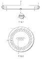
- FIG. 1 is a front view of a fluorescent lamp representing one embodiment of the present invention, wherein a portion thereof is sectioned and enlarged; and FIG. 2 is an enlarged cross-sectional view illustrating a main portion of the fluorescent lamp shown in FIG. 1.
- a fluorescent lamp 10 comprises a glass tube having an outer diameter of 15 to 18 mm and employed as a glass tube 1.
- This glass tube 1 is equipped, on the opposite ends 2 thereof, with filament electrodes 3 functioning as electrode means and enclosed by the glass tube.
- a rare gas such as argon (Ar) is filled together with mercury in the glass tube 1.
- This glass tube 1 is made of soda-lime glass having a thermal expansion coefficient ⁇ ranging from 90 to 100.
- a protective film 4 is formed on the inner surface of the glass tube 1 and a phosphor layer 5 is deposited on the upper surface (the side facing the discharging space) of the protective film 4.
- the thickness of the protective film 4 is confined to 0.8 ⁇ m to 2.0 ⁇ m.
- the protective film 4 comprises, as a major component, SiO 2 fine particles having a specific surface area (BET value) ranging from 60 to 180 m 2 /g, more preferably 90 to 160 m 2 /g and an average primary particle diameter ranging from 13 to 30 nm.
- BET value specific surface area
- the SiO 2 fine particles having an average particle diameter of 25 nm and manufactured by the PVS method are prepared.
- the SiO 2 fine particles are then dispersed in a dispersion medium to prepare a slurry (suspension).
- the slurry thus obtained is used as a raw material for forming the protective film.
- a slurry having a luminescent compound dispersed therein is prepared to obtain a raw material for forming the phosphor layer.
- a raw material for the protective film is coated on the inner wall of the glass tube 1 and dried.
- a raw material for the phosphor layer is coated on the previously coated layer and dried. Subsequently, these coated layers are baked to form the protective film 4 and the phosphor layer 5.
- the phosphor layer 5 may contain a binder which is dispersed in the phosphor layer 5 and comprises, as a major component, the SiO 2 fine particles that have been prepared by the PVS method. Then, an inert gas such as Ar is introduced into the glass tube 1 so as to maintain the inner pressure of the glass tube 1 and, concurrently, the temperature of the glass tube 1 is increased up to 600 to 650°C. Thereafter, the temperature of the glass tube 1 is cooled down to 450°C and the evacuation of the glass tube 1 is performed without contacting the inner wall of the glass tube 1 directly with atmosphere, thus obtaining the fluorescent lamp as shown in FIG. 1.
- an inert gas such as Ar
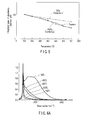
- FIG. 3 is a graph showing the luminous flux maintenance factor of the fluorescent lamp wherein SiO 2 fine particles prepared by the PVS method were employed for forming the protective film 4.
- the luminous flux maintenance factor of the fluorescent lamp wherein SiO 2 fine particles prepared by high-temperature hydrolysis method ("Aerogel MOX80", a trade name of Degxa Co., Ltd.) was employed as a raw material of the protective film
- the luminous flux maintenance factor of the fluorescent lamp wherein Al 2 O 3 fine particles Al 2 O 3 fine particles (Aluminum Oxide C, a trade name of Degxa Co., Ltd.) was employed as a raw material of the protective film, wherein the evacuation of the glass tube 1 was conducted in the same manner as described in this embodiment, are shown in this graph of FIG. 3 as Comparative Examples 1 and 2, respectively.
- a glass tube having an inner diameter of 16.5 mm and a length of 500 mm was used.
- This experiment was performed under the conditions wherein the thickness of the protective film was set to 1 ⁇ m, Ar was employed as a filler gas, and the inner pressure of the glass tube was set to 400 Pa.
- the particle diameter of SiO 2 or Al 2 O 3 becomes larger, the specific surface area of these particles decreases proportionally, thereby making it possible to reduce the quantity of hydroxyl group that adsorbs per unit mass.
- the particle diameter of the fine particles to be employed for the formation of the protective film of the fluorescent lamp becomes larger, it becomes impossible to effectively prevent mercury from being implanted into the glass tube, thus easily causing the darkening of the luminous tube. Therefore, it is required to increase the film thickness of the protective film if the particle diameter of the fine particles is relatively large, resulting in an increase of the absolute quantity of hydroxyl group.
- the specific surface area of the protective film to be formed in the fluorescent lamp and employed in this experiment was set to 110 m 2 /g in the case of the SiO 2 fine particles which were prepared by PVS method, to 80 ⁇ 20 m 2 /g in the case of the SiO 2 fine particles of Comparative Example 1, and to 100 ⁇ 15 m 2 /g in the case of the Al 2 O 3 fine particles of Comparative Examples 2 and 3.
- the film thickness of the protective film was set to 1 ⁇ m in all of the protective films.
- the physical properties of the SiO 2 fine particles (PVS method), of the SiO 2 fine particles of Comparative Example 1, and of the Al 2 O 3 fine particles of Comparative Examples 2 and 3, all employed in this experiment, are shown in the following Table 1.
- the fluorescent lamp of Comparative Example 2 was improved in luminous flux maintenance factor as compared with the fluorescent lamp of Comparative Example 3 that was manufactured by following the conventional evacuation process. It will be also clear that the employment of the SiO 2 fine particles that was manufactured by the PVS method for forming the protective film 4 tends to improve the luminous flux maintenance factor of the fluorescent lamp. In order to examine the reasons for this tendency, the properties of the SiO 2 fine particles which were prepared by the PVS method, of the SiO 2 fine particles of Comparative Example 1, and of the Al 2 O 3 fine particles of Comparative Examples 2 and 3 were investigated.
- the kinds of impurities which may become a cause for generating the darkening of the glass tube are considered as follows. Namely, they are hydroxyl group which is liable to adsorb onto the surface of SiO 2 or Al 2 O 3 which are used for the protective film, HCl which is liable to be mixed into SiO 2 or Al 2 O 3 during the manufacturing process thereof by high-temperature hydrolysis method, and CO and CO 2 which are liable to be generated when the thermal decomposition of an emitter to be coated on the filament electrodes.
- the problem that is considered to be raised on the occasion of using SiO 2 fine particles as a major raw material for forming the protective film is the adsorption of hydroxyl group.
- the SiO 2 fine particles that have been conventionally employed are not surface-treated before use. Therefore, the surfaces of the fine particles are covered with silanol group in air atmosphere, thus indicating hydrophilicity due to the hydrogen bond thereof.
- this silanol group is heated and dehydrated, isolated hydroxyl group and siloxane generate and the silanol group is separated in the form of H 2 O. If it is impossible to separate these impurities in the form of H 2 O as in the case of isolated hydroxyl group, these impurities can be hardly eliminated from the surfaces of SiO 2 fine particles even if they are heated.
- siloxane since siloxane is inactive, if many a number of siloxane is formed on the surfaces of SiO 2 fine particles, hydroxyl group cannot be easily adsorbed onto the surfaces of SiO 2 fine particles. This reaction is considered reversible under a condition of 400°C or less but becomes irreversible under a condition of higher than 400°C. In this manner, the adsorption of hydroxyl group onto the SiO 2 fine particles is highly influenced by the conditions of the surfaces of SiO 2 fine particles.
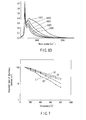
- a sharp peak (a first peak) can be recognized at wave number of 3740 cm -1 .
- This peak is an infrared absorption peak representing isolated hydroxyl group, from which it will be recognized that it cannot be dehydrated even at a measured temperature of about 700°C.
- FIG. 4A shows that most of hydroxyl group other than the isolated hydroxyl group was dehydrated at a temperature ranging from 400 to 500°C.
- a fairly large quantity of hydroxyl group other than the isolated hydroxyl group adsorbs onto the fine particles.
- a broad peak (a second peak) can be recognized at wave number of 3680 cm -1 .
- the intensity ratio between the first peak and the second peak is 70% or more.
- this intensity ratio decreases down to 30% or less.
- the second peak was mostly vanished.
- FIG. 4B it will be recognized that since the intensity ratio was 50% or more, a large number of hydroxyl group, other than isolated hydroxyl group, adsorb onto the SiO 2 fine particles.
- the graph of FIG. 5 indicates that as the inclination of line in downward direction becomes larger, the hydroxyl group adsorbed onto the sample is more liable to be dissociated. It will be recognized from the comparison between the SiO 2 fine particles (PVS method) and the SiO 2 fine particles (Comp. Ex. 1) that the hydroxyl group adsorbed onto the SiO 2 fine particles (PVS method) was more strongly dependent on temperature, enabling the hydroxyl group to be more easily hydrated. It can be assumed from this comparison that the surface condition or structure of SiO 2 fine particles differs depending on the manufacturing method thereof and hence the temperature dependency of the dehydration of hydroxyl group is also caused to differ.
- a raw material is vaporized by the application of thermal energy and then subjected to an oxidation reaction in an oxygen-containing atmosphere to produce oxide fine particles.
- silicon is employed as a raw material and at the same time, a binder comprising carbon as a major component is included, for solidifying silicon, in the raw material prior to the vaporization of raw material. Therefore, the SiO 2 fine particles produced by the PVS method contains a very small amount of carbon.
- impurities are included in the SiO 2 fine particles, there are possibilities of modifying the structure of the SiO 2 fine particles.
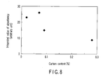
- the present inventors have taken notice of the content of carbon included in the SiO 2 fine particles produced by the PVS method and the infrared absorption spectrum of SiO 2 fine particles was measured while changing the content of carbon, thus investigating the relationship between the temperature and the adsorption of hydroxyl group.
- the graph of FIG. 8 shows the relative values of the integrated value at 700°C, which are plotted relative to the content of carbon.
- This laser Raman spectroscopy is a method for measuring the Raman-scattering light which has been generated from the interaction between laser beam and the molecules of sample as monochromatic laser beam passes through the sample. Since it is possible, through this Raman-scattering light, to selectively observe the vibration mode of absorption band of molecule, the laser Raman spectroscopy is generally employed for the analysis of the structure of molecule.
- This measurement was performed using a sample formed from the compression molding of SiO 2 fine particles at ordinary temperature and a sample formed from the compression molding of SiO 2 fine particles and heated at 700°C, and using laser beams having a wavelength of 633 and 758 nm, respectively.
- FIG. 9A Three kinds of SiO 2 fine particles produced by the PVS method and each differing in content of carbon were prepared and the spectrums thereof were measured at ordinary temperature and by laser Raman spectroscopy.
- the content of carbon of three kinds of SiO 2 fine particles was set to 0.28% by mass, 0.07% by mass (Comparative Example 4) and 0.02% by mass, respectively.
- the results obtained are shown in FIG. 9A as (1), (3) and (4).
- the abscissa thereof represents the wave number (cm -1 ) of Raman-scattering light and the ordinate thereof represents the intensity of Raman-scattering light (intensity/A.u.).
- FIG. 9B shows the spectrums measured of the same three kinds of SiO 2 fine particles at a temperature of 700°C.
- the SiO 2 fine particles of Example 1 (shown by (1)) were caused to change as follows as the temperature thereof was raised.
- the SiO 2 fine particles of Example 1 were produced by the PVS method, the content of carbon included therein being 0.28% by mass.
- the broad spectrum of 200 to 500 cm- 1 was caused to vanish as the temperature thereof was increased, a sharp peak was not formed at a wave number of about 464 cm -1 . Peaks were formed at a wave number of about 494 and 606 cm -1 , respectively.
- the peaks formed at a wave number of about 494 and 606 cm -1 were considered as being the peaks of four-membered ring and three-membered ring, respectively.
- These four-membered ring and three-membered ring are characterized in that the intervals between neighboring hydroxyl groups being adsorbed on the surface are made smaller as compared with many-membered ring as well as with the crystal structure of SiO 2 . Namely, it was assumed that due to the transformation of amorphous structure into a smaller structure such as four-membered ring and three-membered ring in conformity with the rise in temperature, the hydroxyl group was enabled to be easily dissociated.
- the broad spectrum of 200 to 500 cm- 1 was not substantially vanished.
- the SiO 2 fine particles of Example 4 were produced by the PVS method and the carbon content thereof was 0.07%. Although it was possible to recognize the peak of four-membered ring at a wave number of about 494 cm- 1 . the peak of three-membered ring at a wave number of about 606 cm- 1 could be hardly recognized. When the temperature was raised, four-membered ring was formed but three-membered ring was not formed.
- the structure thereof was such that the hydroxyl group was hardly enabled to dissociate.
- SiO 2 fine particles and Al 2 O 3 fine particles to be produced by the high-temperature hydrolysis can be manufactured according to the following chemical formulas (1) and (2), respectively.
- SiCl 4 + 2H 2 + O 2 ⁇ SiO 2 + 4HCl (1)
- HCl will be included in the product. Since HCl is caused to be included in a sample, HCl will be included, as shown in Table 1, in the components of the Al 2 O 3 fine particles and the SiO 2 fine particles to be produced by the high-temperature hydrolysis. If this HCl is left in the glass tube 1, this HCl is considered to react with the mercury that has been sealed into the glass tube, thus raising possibilities of generating one of the causes for darkening the glass tube. The HCl left in the glass tube 1 is originated from those adsorbed onto the Al 2 O 3 and the SiO 2 of the protective film. If this HCl mingles into the Al 2 O 3 and the SiO 2 in the manufacturing process thereof, it has been very difficult to completely eliminate it.
- the SiO 2 fine particles are produced by the PVS method, there is no possibility of permitting HCl to be mingled into the SiO 2 fine particles, since the vapor of Si is directly reacted with oxygen.
- the pH of the slurry of the SiO 2 fine particles produced by the PVS method is 6.5, i.e. neutral. Therefore, it is possible to obtain the protective film having uniform thickness without necessitating accurate control of the pH of aqueous solution.
- SiO 2 fine particles of Examples which were produced by the PVS method were found more advantageous as compared with the SiO 2 fine particles produced by the high-temperature hydrolysis in the case where the evacuation temperature was set higher. The reason for this will be explained as follows.
- a protective film and a phosphor layer are deposited on the inner surface of a glass tube and then the evacuation of the glass tube is performed with the temperature of the glass tube being raised to 450 to 480°C.
- the temperature of glass tube 1 is raised to 600 to 650°C while introducing an inert gas into the glass tube 1. Subsequently, the temperature of the glass tube is lowered to 450 to 480°C and the evacuation is performed without the inner wall of the glass tube 1 being directly contacted with air atmosphere.
- the fluorescent lamp according to the present invention contains a smaller quantity of residual hydroxyl group as compared with the conventional fluorescent lamp. Furthermore, as compared with the SiO 2 fine particles produced by the high-temperature hydrolysis, the SiO 2 fine particles produced by the PVS method are higher in temperature dependency with regard to the dehydration of hydroxyl group. Because of this, the dehydration efficiency at high temperatures can be enhanced. Namely, it is possible, through the heating of about 600 to 700°C, to dehydrate most of the hydroxyl group excepting the isolated hydroxyl group. Therefore, the employment of high temperature higher than the aforementioned range may be of no merit.
- an upper limit of the temperature which makes it possible to adjust the pressure inside the glass tube through the introduction of inert gas may be 650°C.
- the heating of glass tube prior to the evacuation step should preferably be confined to the range of 500 to 650°C, more preferably 550 to 650°C, most preferably 600 to 650°C.
- FIG. 10 shows an electron microscopic photograph illustrating an enlarged cross-section of the fluorescent lamp according to one embodiment of the present invention.
- a protective film and a phosphor layer are successively deposited on the inner surface of a glass tube 1.
- the protective film is formed so as to have a thickness ranging from 0.1 to 2.0 ⁇ m using slurry comprising, as a major component, the SiO 2 fine particles granulated by the PVS method and having an average particle diameter of 25 nm.
- the phosphor layer is dispersed particles of luminescent compound.
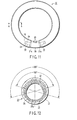
- FIG. 11 is a front view of a circular fluorescent lamp according to one embodiment of the present invention
- FIG. 12 is a cross-sectional view of the tube of the circular fluorescent lamp shown in FIG. 11.
- the film thickness of each of the films and the configuration of the films are partially exaggerated for the convenience of explanation and hence the dimensional ratio of one constituent member relative to other constituent members may differ from the actual dimensional ratio.
- the numeral 21 represents a circular tube which may be formed by bending a cylindrical glass tube formed of soda-lime glass or lead glass, and the numeral 22 represents a stem.
- the numeral 21a represents a sealed portion formed between a terminal portion of the tube 21 and the stem 22, thus constructing an airtight container constituted by the tube 21 and a couple of stems 22.
- the stem 22 is formed of a glass tube having a flare-like configuration and disposed to crushingly seal the junction between a pair of lead wires 24 and an exhaust tube (not shown). Further, between these lead wires 24, there is interposed an electrode 25 formed of a coil-like filament made of a winding of tungsten wire so as to interconnect these lead wires 24.
- the stem 22 may not be formed of a flare stem but may be formed of a button stem or a bead stem.
- the numeral 26 represents a protective film having the same features as described above and being coated substantially all over the inner surface of the tube 21 in order to prevent the darkening of the tube that may be caused by mercury or ultraviolet rays and also to prevent the precipitation of alkaline metals from the tube 21.
- the protective film 26 comprises, as a major component, SiO 2 fine particles produced by the PVS method, having an average particle diameter ranging from 0.01 to 0.05 ⁇ m and a BET value ranging from 90 to 160 cm 2 /g, and containing carbon at ratio of 0.09 to 0.3% by mass, the thickness of the protective film 26 being about 0.1-0.5 ⁇ m.
- a light reflecting translucent film 27 for reflecting visible rays.
- This light reflecting film 27 is coated along the entire length of the tube 21 but limited to a specific region of the tube 21, i.e., an upper inner wall portion of the tube 21, which corresponds to a predetermined angle region in the circumferential direction of the tube.
- This light reflecting film 27 is composed, as a major component, of at least one selected from a luminescent compound, aluminum oxide, titanium oxide and calcium pyrophosphate, each having an average particle diameter of about 0.5-10 ⁇ m.
- the film thickness of the light reflecting film 27 may be 1-40 ⁇ m, preferably about 3-30 ⁇ m, though it may vary depending on the particle diameter thereof.
- this light reflecting film 27 is provided with an opening 27a where this light reflecting film 27 is not deposited, thus exposing the surface of the underlying protective film 26.
- This phosphor layer 28 can be formed by coating fine particles of luminescent compound such as three-wavelength emission type luminescent compound and calcium halophosphate (white emission luminescent compound).
- the tube 21 can be fabricated by, at first, heating a straight tube up to the softening point thereof after finishing the successive deposition of the protective film 26, the light reflecting film 27 and the phosphor layer 28 on the inner surface thereof and then by subjecting it to bending work.
- soda-lime glass or lead glass is generally employed for the manufacture of the tube 21.
- the softening point of these glass materials is around 600 to 700°C, so that they are preliminarily heated up to about 800°C and then subjected to the bending work thereof.
- the SiO 2 fine particles to be employed for the formation of the protective film 26 in the present invention are characterized in that when they are heated up to around 800°C at which the glass material is subjected to bending work, most of hydroxyl group excepting isolated hydroxyl group can be dissociated. Therefore, the dissociation of hydroxyl group that has been adsorbed onto the protective film 26 can be accomplished concurrent with the bending work of the tube 21. After finishing this bending work, the gas existing inside the tube 1 is discharged therefrom and then the end portions thereof are sealed. As described above, in the case of a circular fluorescent lamp, it is not required to perform the introduction of an inert gas into the tube concurrent with the evacuation of the tube, thus facilitating the manufacture thereof.
- the deposition of the protective film 26, the light reflecting film 27 and the phosphor layer 28 can be achieved by the coating of a suspension containing predetermined components.
- This suspension can be prepared by mixing a main component with a binder based on fine particles of metal oxide such as alumina and silica or a binder based on a low-melting point compound such as boric acid and phosphoric acid, and with an organic solvent such as nitrocellulose or a water-soluble solvent such as methyl cellulose, ethyl cellulose, hydroxypropyl cellulose, ammonium polyacrylate, polyethylene oxide, etc.
- the fine particles of metal oxide to be employed as a binder may be the same material to be employed for the formation of the protective film 26.
- the protective film 26 having a thickness of about 0.4 ⁇ m was deposited almost all over the inner surface of the tube 1.
- this protective film 26 there was employed a suspension of fine particles comprising, as a major component, SiO 2 fine particles produced by the PVS method, having an average particle diameter of 0.03 ⁇ m and a BET value of 160 cm 2 /g, and containing carbon at ratio of 0.28% by mass.
- the light reflecting film 27 having a thickness of about 30 ⁇ m was formed on a limited region of the protective film 26, i.e., a region confined by a predetermined angle, for example about 150° in an opening angle in the circumferential direction of the tube (inclined in each side by about 75° from the vertical center line).
- the formation of this light reflecting film 27 was performed using a suspension comprising fine particles including, as a major component, strontium pyrophosphate having an average particle diameter of about 5 um.
- This suspension also contained, as a binder, 4.0% by mass (based on the strontium pyrophosphate) of barium calcium borate (average particle diameter: 4.5 ⁇ m), and also nitrocellulose.
- the barium-calcium borate to be incorporated, as a binder, in the aforementioned fine particles is effective in obtaining a desired adhesion strength if it is incorporated at a ratio of 3 to 6% by mass (preferably, 3.5 to 5.5% by mass) based on strontium pyrophosphate having an average particle diameter ranging from 1.0 to 8.0 ⁇ m. It has been found that if the barium calcium borate is incorporated at a ratio falling outside this range, it will lead to the peeling of the light reflecting film 27 or the deterioration of emission properties of the lamp.
- the phosphor layer 28 having an average thickness of about 25 ⁇ m was formed by using a suspension of mixed fine particles of luminescent compounds and by coating this suspension on the surfaces of the light reflecting film 27 and of the opening portion (light reflection film-missing portion) 27a.
- the luminescent compound it is possible to employ three kinds of luminescent compounds such for example as europium-activated barium ⁇ calcium ⁇ strontium halophosphate (blue emission luminescent compound), cerium ⁇ terbium-activated lanthanum phosphate (green emission luminescent compound), and europium-activated yttrium oxide (red emission luminescent compound), each having an average particle diameter of 3.3 to 4.0 ⁇ m.
- the tube 21 is further filled with liquid or alloyed mercury and 250 to 360 Pa of rare gas such as argon (Ar), krypton (Kr) and neon (Ne), these rare gases being employed singly or in combination of two or more.
- the numeral 29 represents a G10q type base provided with terminal pins 30 and fixed to the opposite sealed ends of the tube 21, thereby bridging these sealed ends.
- the circular fluorescent lamp 20 constructed in this manner can be connected, through the base 29, to a lighting circuit and the lightening thereof is performed by applying electric current, through the base 29 and the lead wires 24, to the electrodes 25.
- the light emits from the entire circumferential surface of the circular tube 21.
- the light cannot be uniformly emitted from the outer peripheral surface located perpendicular to the length of the tube 21.
- the light reflecting film 27 which is high in light reflectance is selectively formed in a circumferentially limited region of the tube 21 which is confined to an angle of 180° or more in the circumferential direction of the tube 21.
- the rest of the tube 21 is occupied by the opening portion 27a which is not provided with the light reflecting film 27. This opening portion 27a is low in light reflectance and high in light transmittance.
- the intensity of light (quantity of light) that can be emitted from this opening portion 27a located on the underside of the tube and extending along the length of the tube will be intensified (or increased) due to the addition of the light which is reflected by the light reflecting film 27 of the tube and directed toward the opening portion 27a, thus further brightening the surface being irradiated by the light emitted from the opening portion. Further, the light also passes through the translucent light reflecting film 27, thus permitting the light to emit also from the upper side of the lamp. In the case of the fluorescent lamp where the distribution of light is controlled as described above, it is possible to utilize the light emitted upwards for enhancing the magnitude of downward illumination by the light reflecting film 27.
- the light reflecting film 27 is expected to be effective in preventing the implantation of mercury, thus making it possible to enhance the luminous flux maintenance factor.
- the film thickness of the light reflecting film 27 should preferably be 20 ⁇ m or more.
- a total thickness thereof would become 40 to 50 ⁇ m, thus rendering them to be easily peeled off.
- the thickness of the protective film 26 is increased to 0.9 ⁇ m or more, the light reflecting film 27 would become easily peelable.
- the thickness of the protective film 26 is decreased to 0.1 ⁇ m or less, it would be impossible to effectively prevent the implantation of mercury into the tube. Therefore, the thickness of the protective film should preferably be confined within the range of 0.3 to 0.7 ⁇ m.
- the light reflecting film 27 can be formed, for example, by coating a suspension containing a reflecting film material on the inner surface of the tube. If a suspension is to be employed, the suspension containing a reflecting film material is at first poured into the tube of a straight glass tube until the tube is filled up with the suspension to a predetermined level as the tube is installed horizontally. For example, straight glass tube is obliquely disposed and then a suspension is poured into the tube from the upper open end while rotating the tube in the circumferential direction thereof. Then, the suspension is disposed in a predetermined range and a redundant portion of the suspension is discharged from the lower open end. Then, the tube is installed horizontally and the suspension disposed in a predetermined range is allowed to dry.
- a spray nozzle is introduced into the tube and the spray nozzle is moved linearly or rockingly along the axis of the tube while ejecting a coating material from this nozzle. Then, the coating liquid coated on and adhered to the inner surface of the tube is allowed to dry. After finishing the drying, the coated liquid is baked to form the light reflecting film 27.
- the major component whose surface is adhered with at least one kind of fine particles selected from oxides of magnesium, calcium, strontium, barium and zinc it is preferable to employ the major component whose surface is adhered with at least one kind of fine particles selected from oxides of magnesium, calcium, strontium, barium and zinc. It is possible, through the employment of such a major component, to prevent the formation of a mercury compound through the reaction of the major component with mercury, thus preventing the coloring or to prevent the shortening of life of the lamp due to the premature consumption of mercury.
- Strontium pyrophosphate, titanium oxide and calcium pyrophosphate are relatively liable to react with mercury or a mercury compound.
- fine particles of magnesium oxide, calcium oxide, strontium oxide, barium oxide or zinc oxide are adhered onto the surface of strontium pyrophosphate, titanium oxide and calcium pyrophosphate, it is possible to control the electrification tendency, etc. As a result, it is possible to inhibit the coloring that may occur due to the reaction between the light reflecting film 27 comprising strontium pyrophosphate, titanium oxide or calcium pyrophosphate with mercury or a compound thereof.
- the average particle diameter of strontium pyrophosphate, titanium oxide or calcium pyrophosphate to be employed as a major component of the light reflecting film 27 should preferably be confined to the range of 1.0 to 8.0 ⁇ m, more preferably about 3.0 to 6.0 ⁇ m.
- the oxides of Mg, Ca, Sr, Ba and Zn should preferably be adhered onto the surface of strontium pyrophosphate, titanium oxide or calcium pyrophosphate particles at a ratio of 0.01 to 5.0% by mass, more preferably at a ratio of 0.02 to 3.0% by mass based on the these major components.
- Fine particles of magnesium oxide, calcium oxide, strontium oxide, barium oxide or zinc oxide may be adhered also onto the surface of luminescent compound constituting the phosphor layer 28 other than the aforementioned major components employed for forming the light reflecting film 27. Even when these oxides are adhered onto the surface of luminescent compound, it is possible to inhibit the coloring of the phosphor layer 28 due to the effects of mercury or a compound thereof and also to inhibit the exhaustion of mercury, thus obtaining almost the same effects as described above.
- These oxides may be adhered onto the surface of particles of major components in the form of fine particles having an average particle diameter ranging from 5 to 100 ⁇ m or in the form of homogeneous coated layer.
- the protective film 26, the light reflecting translucent film (or light reflecting film) 27 and the phosphor layer 28 were successively deposited, as a laminate, on the inner surface of the tube 21.
- the light reflecting film 27 is formed at first using reflecting film-forming materials including an organic binder and then the phosphor layer 28 is formed using a slurry of luminescent compound containing an organic solvent, the underlying light reflecting film 27 sometimes dissolves into the organic solvent of the slurry of luminescent compound.
- a light reflecting film-forming material is coated and then baked to form the light reflecting film 27, after which a luminescent compound suspension is coated over this light reflecting film 27 and then baked to form the phosphor layer 28.
- a boron-based binder is to be employed for forming the light reflecting film 27, the luminescent compound chemically react with this binder, thereby deteriorating the luminescent compound. As a result, the luminous flux may be degraded.
- the laminate may be formed by successively depositing the light reflecting translucent film 27, the protective film 26 and the phosphor layer 28 in the mentioned order as shown in FIG. 13. If the laminate is constructed in this manner, both of the light reflecting film 27 and the phosphor layer 28 may be formed using an organic slurry. Further, when the protective film 26 is formed using an aqueous colloidal solution, the manufacture of the laminate can be facilitated and at the same time, the generation of reaction between the binder to be incorporated in the light reflecting film 27 and the luminescent compound can be prevented.
- the laminate having the aforementioned structure can be formed by the process as described below.
- calcium pyrophosphate is dispersed in a butyl acetate solution containing 1 wt% of nitrocellulose to prepare a suspension to be employed as a raw material for forming the light reflecting film.
- this suspension was coated to form a coated layer having a thickness of about 30 um on a specific region of the inner surface of the tube 21, i.e., a region which is confined to an angle of about 200° in radial direction of the tube 21, the coated layer being subsequently dried to form the light reflecting film.
- a predetermined SiO 2 fine particles is dispersed in water to prepare a colloidal solution.
- This colloidal solution is coated on the light reflecting film and on the exposed inner surface of the tube and dried to form the protective film having a thickness of about 1 ⁇ m.
- a luminescent compound is dispersed in a butyl acetate solution containing 1 wt% of nitrocellulose to obtain a raw phosphor material, which is then coated on the protective film to a thickness of about 20 ⁇ m and dried.
- the resultant tube 21 is placed in a kiln and baked to form a three-ply film. Then, a stem is sealingly attached to the opposite ends of the tube 21 and the tube 21 is bent into a circular configuration. Thereafter, the evacuation, the attachment of a base and the aging of the tube are performed to accomplish a circular fluorescent lamp 20.
- the present invention is limited to such a configuration. Namely, the present invention can be applied also to a straight fluorescent lamp, a compact fluorescent lamp, a U-shaped fluorescent lamp, and a bulb type fluorescent lamp wherein a plurality of U-shaped fluorescent lamps are connected with each other to form a composite luminous tube.
- FIG. 14 shows a schematic view of one example of lighting fixture wherein the aforementioned straight fluorescent lamp is employed.
- This lighting fixture D shown in FIG. 14 is a ceiling surface-mounting type lighting fixture.
- the symbol D1 represent a main body of lighting fixture, in which an attachment (not shown) for mounting the lighting fixture on a ceiling, a power source connecting mechanism and a ballast D2 are disposed.
- a pair of lamp sockets D3 are attached below the main body D1 and a fluorescent lamp 10 is mounted between these lamp sockets D3.
- This fluorescent lamp 10 is sustained by these lamp sockets D3. Electric power is applied to this fluorescent lamp 10 through the ballast D2 and the lamp sockets D3, thus enabling the fluorescent lamp 10 to be lightened stably.
Landscapes
- Luminescent Compositions (AREA)
- Vessels And Coating Films For Discharge Lamps (AREA)
- Surface Treatment Of Glass (AREA)
Applications Claiming Priority (2)
| Application Number | Priority Date | Filing Date | Title |
|---|---|---|---|
| JP2005363550 | 2005-12-16 | ||
| JP2006163923 | 2006-06-13 |
Publications (2)
| Publication Number | Publication Date |
|---|---|
| EP1798754A2 true EP1798754A2 (fr) | 2007-06-20 |
| EP1798754A3 EP1798754A3 (fr) | 2012-07-04 |
Family
ID=37758736
Family Applications (1)
| Application Number | Title | Priority Date | Filing Date |
|---|---|---|---|
| EP06256403A Withdrawn EP1798754A3 (fr) | 2005-12-16 | 2006-12-15 | Lampe fluorescente ayant une couche protectrice, et luminaire l'utilisant |
Country Status (2)
| Country | Link |
|---|---|
| EP (1) | EP1798754A3 (fr) |
| CN (1) | CN101017765B (fr) |
Cited By (1)
| Publication number | Priority date | Publication date | Assignee | Title |
|---|---|---|---|---|
| RU2595251C1 (ru) * | 2015-04-08 | 2016-08-27 | Общество с ограниченной ответственностью "Научно-исследовательский институт источников света имени А.Н. Лодыгина" | Газоразрядная бактерицидная лампа |
Family Cites Families (5)
| Publication number | Priority date | Publication date | Assignee | Title |
|---|---|---|---|---|
| US4923425A (en) * | 1987-06-12 | 1990-05-08 | Gte Products Corporation | Fluorescent lamp with a predetermined CRI and method for making |
| CN1089188C (zh) * | 1995-07-31 | 2002-08-14 | 松下电器产业株式会社 | 荧光灯及其制造方法 |
| JP3603617B2 (ja) * | 1998-10-02 | 2004-12-22 | 松下電工株式会社 | 蛍光ランプ及び放電灯点灯装置 |
| JP2002251983A (ja) * | 2001-02-23 | 2002-09-06 | Harison Toshiba Lighting Corp | 無電極放電ランプ装置および紫外線照射装置 |
| EP1734563A3 (fr) * | 2005-06-17 | 2009-08-12 | Toshiba Lighting & Technology Corporation | Lampe fluorescente ayant une couche protectrice, et dispositif d'éclairage l'utilisant |
-
2006
- 2006-12-15 CN CN2006101681528A patent/CN101017765B/zh not_active Expired - Fee Related
- 2006-12-15 EP EP06256403A patent/EP1798754A3/fr not_active Withdrawn
Cited By (1)
| Publication number | Priority date | Publication date | Assignee | Title |
|---|---|---|---|---|
| RU2595251C1 (ru) * | 2015-04-08 | 2016-08-27 | Общество с ограниченной ответственностью "Научно-исследовательский институт источников света имени А.Н. Лодыгина" | Газоразрядная бактерицидная лампа |
Also Published As
| Publication number | Publication date |
|---|---|
| CN101017765B (zh) | 2010-09-29 |
| EP1798754A3 (fr) | 2012-07-04 |
| CN101017765A (zh) | 2007-08-15 |
Similar Documents
| Publication | Publication Date | Title |
|---|---|---|
| EP0464179B1 (fr) | Phosphores presentant une amelioration du flux lumineux et lampes realisees a partir de ceux-ci | |
| US5985175A (en) | Boron oxide coated phosphor and method of making same | |
| KR100480882B1 (ko) | 형광 램프와 그 제조방법 및 이를 이용한 정보표시장치 | |
| US5051653A (en) | Silicon dioxide selectively reflecting layer for mercury vapor discharge lamps | |
| CN1659681A (zh) | 一种荧光灯及其制造方法 | |
| EP0249743A2 (fr) | Lampes à décharge à enveloppes à arc en céramique revêtue et leur fabrication | |
| US5113118A (en) | Phosphors with improved lumen output and lamps made therefrom | |
| JP2003051284A (ja) | 蛍光ランプおよび照明器具 | |
| EP1798754A2 (fr) | Lampe fluorescente ayant une couche protectrice, et luminaire l'utilisant | |
| EP0257554B1 (fr) | Particule de matière luminescente, mélange de matière luminescente, et lampe fluorescente | |
| KR100478304B1 (ko) | 형광 램프 및 조명장치 | |
| US6919679B2 (en) | Contaminant getter on UV reflective base coat in fluorescent lamps | |
| EP1887610A1 (fr) | Lampe fluorescente et son procédé de production, et illuminateur | |
| JP4771169B2 (ja) | 蛍光ランプおよび照明装置 | |
| JP4662778B2 (ja) | 電灯および蛍光灯 | |
| JP3678203B2 (ja) | ガラス組成物、保護層組成物、結着剤組成物、蛍光ランプ用ガラス管、蛍光ランプ、高輝度放電ランプ用外管及び高輝度放電ランプ | |
| JP2005524929A (ja) | 低圧水銀放電ランプ | |
| JPH07268318A (ja) | 蛍光体、蛍光体の製造方法および蛍光ランプ | |
| JP2001098261A (ja) | 発光組成物及びそれを用いたカラー蛍光ランプ | |
| JP2000156202A (ja) | 蛍光ランプ | |
| JP2000223075A (ja) | 放電ランプ、蛍光ランプおよび照明装置 | |
| JP2004006399A (ja) | 蛍光ランプ | |
| JPH07183005A (ja) | 高負荷蛍光ランプ | |
| Jackson et al. | Some Factors Affecting the Efficiency of Fluorescent Lamps—The Quest for Higher Luminous Output | |
| JPH11111228A (ja) | 蛍光ランプ |
Legal Events
| Date | Code | Title | Description |
|---|---|---|---|
| PUAI | Public reference made under article 153(3) epc to a published international application that has entered the european phase |
Free format text: ORIGINAL CODE: 0009012 |
|
| AK | Designated contracting states |
Kind code of ref document: A2 Designated state(s): AT BE BG CH CY CZ DE DK EE ES FI FR GB GR HU IE IS IT LI LT LU LV MC NL PL PT RO SE SI SK TR |
|
| AX | Request for extension of the european patent |
Extension state: AL BA HR MK YU |
|
| PUAL | Search report despatched |
Free format text: ORIGINAL CODE: 0009013 |
|
| RIC1 | Information provided on ipc code assigned before grant |
Ipc: H01J 61/72 20060101ALI20120523BHEP Ipc: H01J 61/35 20060101AFI20120523BHEP |
|
| AK | Designated contracting states |
Kind code of ref document: A3 Designated state(s): AT BE BG CH CY CZ DE DK EE ES FI FR GB GR HU IE IS IT LI LT LU LV MC NL PL PT RO SE SI SK TR |
|
| AX | Request for extension of the european patent |
Extension state: AL BA HR MK RS |
|
| RIC1 | Information provided on ipc code assigned before grant |
Ipc: H01J 61/72 20060101ALI20120530BHEP Ipc: H01J 61/35 20060101AFI20120530BHEP |
|
| AKY | No designation fees paid | ||
| REG | Reference to a national code |
Ref country code: DE Ref legal event code: R108 |
|
| REG | Reference to a national code |
Ref country code: DE Ref legal event code: R108 Effective date: 20130313 |
|
| STAA | Information on the status of an ep patent application or granted ep patent |
Free format text: STATUS: THE APPLICATION IS DEEMED TO BE WITHDRAWN |
|
| 18D | Application deemed to be withdrawn |
Effective date: 20130105 |