EP1798967A2 - Anzeigevorrichtung - Google Patents
Anzeigevorrichtung Download PDFInfo
- Publication number
- EP1798967A2 EP1798967A2 EP06256341A EP06256341A EP1798967A2 EP 1798967 A2 EP1798967 A2 EP 1798967A2 EP 06256341 A EP06256341 A EP 06256341A EP 06256341 A EP06256341 A EP 06256341A EP 1798967 A2 EP1798967 A2 EP 1798967A2
- Authority
- EP
- European Patent Office
- Prior art keywords
- chassis
- display device
- cabinet
- board
- internal components
- Prior art date
- Legal status (The legal status is an assumption and is not a legal conclusion. Google has not performed a legal analysis and makes no representation as to the accuracy of the status listed.)
- Withdrawn
Links
Images


Classifications
-
- H—ELECTRICITY
- H04—ELECTRIC COMMUNICATION TECHNIQUE
- H04N—PICTORIAL COMMUNICATION, e.g. TELEVISION
- H04N5/00—Details of television systems
- H04N5/64—Constructional details of receivers, e.g. cabinets or dust covers
Definitions
- the present invention relates to a display device, and more specifically, to a display device such as a liquid crystal display or a plasma display comprising a casing composed of a front cabinet and a back cabinet constituting the external appearance of the device and capable of being divided to front and rear portions, a display unit disposed in the interior of the casing and exposed to the exterior through an opening window formed on the front cabinet, and a chassis similarly assembled in the interior of the cabinet positioned on the rear side of the display unit.
- display devices utilizing liquid crystal or plasma for displaying video images such as television programs, DVD and video or for displaying the screen of personal computers
- Such display devices are respectively equipped with a display panel utilizing liquid crystal or plasma, display device supporting means for supporting the display device, a chassis for mounting the same, various circuit boards and a casing, but conventionally, these various components are assembled in a complex manner in order to manufacture the display device.
- the various circuit boards are mounted on various areas of the chassis, the casing and the like. Therefore, the assembly operation is complex.
- Patent document 1 discloses an art of simplifying the assembly operation by supporting and fixing the internal components via the casing, and an art of realizing a superior positional accuracy by providing ribs on the casing for supporting the components.
- the present invention aims at solving the problems mentioned above, by providing a display device capable of simplifying the assembly operation and maintenance operation. Furthermore, the present invention aims at providing a display device capable of simplifying the molds for forming the casing and reducing a sink mark occurring on the surface of the casing.
- the display device comprises a chassis and internal components disposed in an interior of a front cabinet constituting a front portion and a back cabinet constituting a rear portion of a casing capable of being divided in front and rear directions, characterized in that all the internal components are mounted on the chassis.
- the display device comprises a display device according to aspect 1, wherein the internal components are a display panel and a circuit board, and wherein an opening is formed on substantially the center area of the front cabinet, through which opening the display panel is exposed.
- the display device comprises a display device according to aspect 1, wherein the internal components are a display panel, a power supply board, an AV board, an MPEG board, a speaker, a recording and reproducing unit and an operation board, and wherein an opening is formed on substantially the center area of the front cabinet, through which opening the display panel is exposed, and an operation button is formed integrally on the surface of the front cabinet.
- the internal components are a display panel, a power supply board, an AV board, an MPEG board, a speaker, a recording and reproducing unit and an operation board, and wherein an opening is formed on substantially the center area of the front cabinet, through which opening the display panel is exposed, and an operation button is formed integrally on the surface of the front cabinet.
- the present invention it becomes possible to provide a display device capable of simplifying the assembly operation and maintenance operation by having all the internal components mounted on the chassis. Furthermore, it becomes possible to provide a display device capable of simplifying the molds for forming the casing and reducing the occurrence of the sink mark on the surface of the casing, since there is no need to form ribs for mounting internal components on the casing.
- the chassis acts as a basis to assemble all the internal components into a single unit to which the front cabinet and the back cabinet constituting the casing are attached, the components which were conventionally respectively attached to the casing and the chassis can all be assembled on a single chassis, so that the operation steps for manufacturing the display device can be improved. Furthermore, the maintenance operation such as repairing and testing operation can be performed by simply separating the front cabinet and the back cabinet.
- the forms of the front cabinet and the back cabinet can be simplified, and the molds for forming the same can also be desirably simplified, according to which the costs related to manufacturing the molds can be cut down.
- bosses and ribs formed on the front and back cabinets are reduced, the drawbacks related to the appearance of the front cabinet and the back cabinet such as the sink mark formed on the surface thereof can be reduced.
- the front cabinet and the back cabinet that are to be assembled to the front and rear sides of the internal unit are directly fixed to each other via screws, so that the number of screws can be reduced compared to the case where each cabinet is attached respectively to the internal unit, and the costs of the display device can be reduced by the reduction in the number of components.
- FIG. 1 is a perspective view showing the external appearance of a display device 1.
- the casing thereof is dividable into front and rear areas, and it is composed of a front cabinet 2 and a back cabinet 3.
- An opening window is formed on substantially the center portion of the front cabinet 2, through which is exposed a display panel 42.
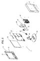
- FIG. 4 is an exploded perspective view showing the state prior to attaching the front cabinet 2 and the back cabinet 3 to the internal unit 4.
- the front cabinet 2 and the back cabinet 3 are directly engaged via screws 7.
- FIGS. 5A and 5B are partially cross-sectional perspective view and cross-sectional side view of the display device 1.
- FIG. 2 is an exploded perspective view illustrating the internal components of the display device 1.
- the internal components include the display panel 42 for displaying images, various circuit boards (such as a power supply board 43 for converting the input voltage supplied from an external power supply to a voltage used in the display device 1, an AV board 44 for processing audio signals and video signals, and an MPEG board 45 for encoding and decoding MPEG), a speaker 46 for outputting audio, a recording and reproducing unit 47 for recording and reproducing data on a DVD, the operation board 48 having switches being turned on and off in conjunction with an operation button 22 operated by a user by pressing the button, and a display device supporting means composed of a stand supporting unit 49 and a stand 50 for supporting the display device 1.
- These internal components are all mounted on a chassis 41.
- the front cabinet 2 has an opening window 21 formed substantially at the center thereof, and the operation button 22 disposed on the upper surface thereof.
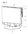
- FIG. 3 is a perspective view showing the internal unit 4 in which the internal components are formed into a unit with the chassis 41 acting as the basis, wherein all the internal components are mounted on the chassis 41.
- the display panel 42 is mounted on the front side of the chassis 41 (the side on which the front cabinet 2 will be positioned), and various circuit boards (power supply board 43, AV board 44 and MPEG board 45), the speaker 46 and the recording and reproducing unit 47 are mounted on the rear side of the chassis 41 (the side on which the back cabinet 3 will be positioned).
- a stand supporting unit 49 is attached to the bottom side of the chassis 41, and an operation board 48 is mounted on the upper surface of the chassis 41.
- the operation board 48 is mounted on the upper surface of the chassis 41, but the present invention is not restricted thereto, and the operation board 48 can be mounted on the chassis 41 corresponding to where the operation button 22 is disposed.
- the display device 1 is a display device 1 having a built-in recording and reproducing unit 47, but the present invention is not restricted thereto, and the display device can be a display device 1 without a built-in recording and reproducing unit 47.
- the display surface of the display panel 42 is positioned downward, and the chassis 41 is placed on the rear side of the display panel 42 (for example, if the display unit of the display panel 42 is disposed on the mounting surface such as a table, the rear side corresponds to the upper side of the display panel 42 placed on the mounting surface), and screws 7 are engaged from the side surfaces of the chassis 41 so as to assemble the display panel 42 with the chassis 41.
- the stand supporting unit 49 having the stand 50 attached thereto in advance is fixed via screws 7 to the bottom side of the chassis 41.
- the chassis 41 is raised so that the bottom side of the stand 50 is disposed as the mounting surface side, and then the operation board 48 having switches is fixed via screws 7 to the upper side of the chassis 41.
- the internal components of the display device 1 are formed as a unit with the chassis 41 acting as the basis (this unit is called the internal unit 4).
- front cabinet 2 and the back cabinet 3 are assembled and fixed via screws 7 to the front side of the internal unit 4 (on the side of the chassis 41 where the display panel 42 is mounted) and the rear side thereof (the side of the chassis 41 on which the various circuit boards, the speaker 46 and the recording and reproducing unit 47 are mounted).
- the order for mounting the internal components on the chassis 41 can be varied from that described above (that is, the various circuit boards, the stand supporting unit 49 and the like can be mounted on the chassis 41 before mounting the display panel 42, as long as the front cabinet 2 and the back cabinet 3 constituting the casing are mounted at the final step).
- the front cabinet 2 and the back cabinet 3 has bosses and holes formed thereto for directly engaging the front cabinet 2 and the back cabinet 3 via screws 7. That is, by engaging the front cabinet 2 and the back cabinet 3 directly, it becomes possible to reduce the number of screws 7 used for engagement compared to the case where the front cabinet 2 and the back cabinet 3 are respectively engaged and fixed to the internal unit 4.
- through holes to the chassis 41 of the internal unit 4 capable of having bosses formed on the front cabinet 2 pass therethrough, so that the bosses on the front cabinet 2 can be protruded through the through holes to the rear side of the internal unit 4 and assembled with the holes on the back cabinet 3, and have screws 7 engaged thereto from the rear side of the back cabinet 3.
- the present invention enables to provide a display device capable of simplifying the assembling operation and maintenance operation by having all the internal components mounted on the chassis. Further, the present invention provides a display device where the casing does not have any ribs for mounting the internal components, so that the casing can be formed using simplified molds, and the occurrence of a sink mark on the surface of the casing can be reduced. Moreover, the present invention provides a display device capable of reducing the number of screws by designing the front cabinet and the back cabinet to be fixed to each other directly via screws.
Landscapes
- Engineering & Computer Science (AREA)
- Multimedia (AREA)
- Signal Processing (AREA)
- Devices For Indicating Variable Information By Combining Individual Elements (AREA)
- Liquid Crystal (AREA)
Applications Claiming Priority (1)
| Application Number | Priority Date | Filing Date | Title |
|---|---|---|---|
| JP2005360339A JP2007163861A (ja) | 2005-12-14 | 2005-12-14 | 表示装置 |
Publications (2)
| Publication Number | Publication Date |
|---|---|
| EP1798967A2 true EP1798967A2 (de) | 2007-06-20 |
| EP1798967A3 EP1798967A3 (de) | 2008-03-05 |
Family
ID=37903466
Family Applications (1)
| Application Number | Title | Priority Date | Filing Date |
|---|---|---|---|
| EP06256341A Withdrawn EP1798967A3 (de) | 2005-12-14 | 2006-12-13 | Anzeigevorrichtung |
Country Status (3)
| Country | Link |
|---|---|
| US (1) | US20070133158A1 (de) |
| EP (1) | EP1798967A3 (de) |
| JP (1) | JP2007163861A (de) |
Cited By (4)
| Publication number | Priority date | Publication date | Assignee | Title |
|---|---|---|---|---|
| EP2076107A3 (de) * | 2007-12-28 | 2009-10-07 | Orion Electric Co., Ltd | Anzeigevorrichtung |
| EP2180719A2 (de) | 2008-10-22 | 2010-04-28 | Vestel Elektronik Sanayi ve Ticaret A.S. | Lautsprechergitter |
| EP2350942A1 (de) * | 2008-09-19 | 2011-08-03 | Logomotion, s.r.o. | Elektronisches bezahlungsanwendungssystem und bezahlungsautorisierungsverfahren |
| EP2565743A3 (de) * | 2011-08-30 | 2014-11-26 | Funai Electric Co., Ltd. | Anzeigevorrichtung und Fernsehvorrichtung |
Families Citing this family (10)
| Publication number | Priority date | Publication date | Assignee | Title |
|---|---|---|---|---|
| CN1582105B (zh) * | 2003-08-04 | 2010-05-26 | 三星电子株式会社 | 显示装置及其方法 |
| US7969719B2 (en) | 2006-01-04 | 2011-06-28 | Westinghouse Digital, Llc | Back panel for video display device |
| US20080186664A1 (en) * | 2006-10-04 | 2008-08-07 | Westinghouse Digital Electronics, Llc | Back Panel for Video Display Device Including Replaceable Slide-Out Electronic Components |
| TWI375505B (en) * | 2008-10-24 | 2012-10-21 | Wistron Corp | Frame structure and display apparatus using the same |
| CN101729954B (zh) * | 2008-10-28 | 2013-08-07 | 深圳富泰宏精密工业有限公司 | 音腔结构 |
| CN102262418A (zh) * | 2010-05-27 | 2011-11-30 | 鸿富锦精密工业(深圳)有限公司 | 台式电脑 |
| TWM395870U (en) * | 2010-08-10 | 2011-01-01 | Jazz Hipster Corp | Hanging structure for electronic whiteboard sound device |
| JP5877318B2 (ja) | 2010-09-28 | 2016-03-08 | パナソニックIpマネジメント株式会社 | ディスプレイ装置 |
| EP2693263A1 (de) | 2012-07-31 | 2014-02-05 | Orion Electric Company, LTD. | Anzeigevorrichtung |
| KR102209145B1 (ko) * | 2014-08-18 | 2021-01-29 | 삼성디스플레이 주식회사 | 표시 장치 |
Family Cites Families (6)
| Publication number | Priority date | Publication date | Assignee | Title |
|---|---|---|---|---|
| TW445386B (en) * | 1998-03-16 | 2001-07-11 | Hitachi Ltd | Thin-type display |
| US6229584B1 (en) * | 1999-11-15 | 2001-05-08 | Compal Electronics, Inc. | Liquid crystal display monitor having a monitor stand with a replaceable housing part |
| KR100369821B1 (ko) * | 2000-12-27 | 2003-02-05 | 삼성전자 주식회사 | 디스플레이장치 |
| KR100445033B1 (ko) * | 2002-08-26 | 2004-08-18 | 삼성에스디아이 주식회사 | 전자부품 수납용 케이스 및 이를 구비한 화상표시장치 |
| KR100581863B1 (ko) * | 2003-10-09 | 2006-05-22 | 삼성에스디아이 주식회사 | 플라즈마 디스플레이 장치 |
| JP2005295146A (ja) * | 2004-03-31 | 2005-10-20 | Orion Denki Kk | Dvd等の記録再生装置を搭載した液晶テレビジョン装置 |
-
2005
- 2005-12-14 JP JP2005360339A patent/JP2007163861A/ja active Pending
-
2006
- 2006-12-11 US US11/636,662 patent/US20070133158A1/en not_active Abandoned
- 2006-12-13 EP EP06256341A patent/EP1798967A3/de not_active Withdrawn
Cited By (5)
| Publication number | Priority date | Publication date | Assignee | Title |
|---|---|---|---|---|
| EP2076107A3 (de) * | 2007-12-28 | 2009-10-07 | Orion Electric Co., Ltd | Anzeigevorrichtung |
| EP2350942A1 (de) * | 2008-09-19 | 2011-08-03 | Logomotion, s.r.o. | Elektronisches bezahlungsanwendungssystem und bezahlungsautorisierungsverfahren |
| AU2009294210B2 (en) * | 2008-09-19 | 2015-11-19 | Smk-Logomotion Corporation | The electronic payment application system and payment authorization method |
| EP2180719A2 (de) | 2008-10-22 | 2010-04-28 | Vestel Elektronik Sanayi ve Ticaret A.S. | Lautsprechergitter |
| EP2565743A3 (de) * | 2011-08-30 | 2014-11-26 | Funai Electric Co., Ltd. | Anzeigevorrichtung und Fernsehvorrichtung |
Also Published As
| Publication number | Publication date |
|---|---|
| JP2007163861A (ja) | 2007-06-28 |
| US20070133158A1 (en) | 2007-06-14 |
| EP1798967A3 (de) | 2008-03-05 |
Similar Documents
| Publication | Publication Date | Title |
|---|---|---|
| EP1798967A2 (de) | Anzeigevorrichtung | |
| US8023260B2 (en) | Assembly of an electronic device | |
| KR100383428B1 (ko) | 액정 모듈 장착용 구조체와 이 구조체를 이용한 휴대용데이터 단말기 또는 정보 처리 장치 | |
| JP4199292B1 (ja) | 表示装置 | |
| JP2017084413A (ja) | 電子装置ハウジング及び組み立て方法 | |
| JP2001033761A (ja) | 液晶モジュール取付け構造 | |
| US20060209228A1 (en) | Liquid crystal display device with LCD cover | |
| JP2008141139A (ja) | 電子機器、フレキシブル基板および基板固定部材 | |
| US20060016675A1 (en) | Supporting device for control buttons of electronic instruments and electronic instruments adapting the same | |
| KR101164822B1 (ko) | 정보처리장치 및 그 제작방법 | |
| US20080130213A1 (en) | Electronic apparatus and component | |
| JP2009159084A (ja) | 表示装置 | |
| US20060002063A1 (en) | Liquid crystal display device | |
| JP4122460B2 (ja) | ディスク装置一体型液晶表示装置 | |
| JP2005100173A (ja) | 情報機器 | |
| US7061751B2 (en) | Electronic apparatus with a speaker | |
| US20070206123A1 (en) | Liquid crystal television | |
| JP4937707B2 (ja) | 金属製ハウジング及び装飾用エンベロプを含む電子デバイス | |
| JP2010233138A (ja) | 表示装置 | |
| JP2007114566A (ja) | 操作ボタンを備えた映像表示装置及びその組み立て方法 | |
| JP2005191029A (ja) | 操作ボタン及び操作ボタンを備えた電気機器 | |
| JP4116375B2 (ja) | 薄型表示装置 | |
| US20120236215A1 (en) | Tv receiver and electronic apparatus | |
| JP2007235413A (ja) | 液晶テレビジョン受像機 | |
| JP2005243399A (ja) | 操作ボタン及び操作ボタンを備えた電気機器 |
Legal Events
| Date | Code | Title | Description |
|---|---|---|---|
| PUAI | Public reference made under article 153(3) epc to a published international application that has entered the european phase |
Free format text: ORIGINAL CODE: 0009012 |
|
| AK | Designated contracting states |
Kind code of ref document: A2 Designated state(s): AT BE BG CH CY CZ DE DK EE ES FI FR GB GR HU IE IS IT LI LT LU LV MC NL PL PT RO SE SI SK TR |
|
| AX | Request for extension of the european patent |
Extension state: AL BA HR MK YU |
|
| PUAL | Search report despatched |
Free format text: ORIGINAL CODE: 0009013 |
|
| AK | Designated contracting states |
Kind code of ref document: A3 Designated state(s): AT BE BG CH CY CZ DE DK EE ES FI FR GB GR HU IE IS IT LI LT LU LV MC NL PL PT RO SE SI SK TR |
|
| AX | Request for extension of the european patent |
Extension state: AL BA HR MK YU |
|
| AKX | Designation fees paid | ||
| REG | Reference to a national code |
Ref country code: DE Ref legal event code: 8566 |
|
| STAA | Information on the status of an ep patent application or granted ep patent |
Free format text: STATUS: THE APPLICATION IS DEEMED TO BE WITHDRAWN |
|
| 18D | Application deemed to be withdrawn |
Effective date: 20080906 |