EP1799018A2 - Carte à circuit électrique, dispositif de cartes à circuit, moteur, dispositif avec moteur, pompe électrique et procédé de connexion d'un moteur avec une pompe - Google Patents
Carte à circuit électrique, dispositif de cartes à circuit, moteur, dispositif avec moteur, pompe électrique et procédé de connexion d'un moteur avec une pompe Download PDFInfo
- Publication number
- EP1799018A2 EP1799018A2 EP06026092A EP06026092A EP1799018A2 EP 1799018 A2 EP1799018 A2 EP 1799018A2 EP 06026092 A EP06026092 A EP 06026092A EP 06026092 A EP06026092 A EP 06026092A EP 1799018 A2 EP1799018 A2 EP 1799018A2
- Authority
- EP
- European Patent Office
- Prior art keywords
- motor
- electrical circuit
- board
- circuit board
- nut
- Prior art date
- Legal status (The legal status is an assumption and is not a legal conclusion. Google has not performed a legal analysis and makes no representation as to the accuracy of the status listed.)
- Withdrawn
Links
Images





Classifications
-
- H—ELECTRICITY
- H05—ELECTRIC TECHNIQUES NOT OTHERWISE PROVIDED FOR
- H05K—PRINTED CIRCUITS; CASINGS OR CONSTRUCTIONAL DETAILS OF ELECTRIC APPARATUS; MANUFACTURE OF ASSEMBLAGES OF ELECTRICAL COMPONENTS
- H05K1/00—Printed circuits
- H05K1/02—Details
- H05K1/0213—Electrical arrangements not otherwise provided for
- H05K1/0263—High current adaptations, e.g. printed high current conductors or using auxiliary non-printed means; Fine and coarse circuit patterns on one circuit board
-
- H—ELECTRICITY
- H02—GENERATION; CONVERSION OR DISTRIBUTION OF ELECTRIC POWER
- H02K—DYNAMO-ELECTRIC MACHINES
- H02K11/00—Structural association of dynamo-electric machines with electric components or with devices for shielding, monitoring or protection
- H02K11/30—Structural association with control circuits or drive circuits
- H02K11/33—Drive circuits, e.g. power electronics
-
- H—ELECTRICITY
- H01—ELECTRIC ELEMENTS
- H01R—ELECTRICALLY-CONDUCTIVE CONNECTIONS; STRUCTURAL ASSOCIATIONS OF A PLURALITY OF MUTUALLY-INSULATED ELECTRICAL CONNECTING ELEMENTS; COUPLING DEVICES; CURRENT COLLECTORS
- H01R12/00—Structural associations of a plurality of mutually-insulated electrical connecting elements, specially adapted for printed circuits, e.g. printed circuit boards [PCB], flat or ribbon cables, or like generally planar structures, e.g. terminal strips, terminal blocks; Coupling devices specially adapted for printed circuits, flat or ribbon cables, or like generally planar structures; Terminals specially adapted for contact with, or insertion into, printed circuits, flat or ribbon cables, or like generally planar structures
- H01R12/50—Fixed connections
- H01R12/51—Fixed connections for rigid printed circuits or like structures
- H01R12/52—Fixed connections for rigid printed circuits or like structures connecting to other rigid printed circuits or like structures
- H01R12/523—Fixed connections for rigid printed circuits or like structures connecting to other rigid printed circuits or like structures by an interconnection through aligned holes in the boards or multilayer board
-
- H—ELECTRICITY
- H05—ELECTRIC TECHNIQUES NOT OTHERWISE PROVIDED FOR
- H05K—PRINTED CIRCUITS; CASINGS OR CONSTRUCTIONAL DETAILS OF ELECTRIC APPARATUS; MANUFACTURE OF ASSEMBLAGES OF ELECTRICAL COMPONENTS
- H05K1/00—Printed circuits
- H05K1/02—Details
- H05K1/14—Structural association of two or more printed circuits
- H05K1/144—Stacked arrangements of planar printed circuit boards
-
- H—ELECTRICITY
- H05—ELECTRIC TECHNIQUES NOT OTHERWISE PROVIDED FOR
- H05K—PRINTED CIRCUITS; CASINGS OR CONSTRUCTIONAL DETAILS OF ELECTRIC APPARATUS; MANUFACTURE OF ASSEMBLAGES OF ELECTRICAL COMPONENTS
- H05K2201/00—Indexing scheme relating to printed circuits covered by H05K1/00
- H05K2201/10—Details of components or other objects attached to or integrated in a printed circuit board
- H05K2201/10227—Other objects, e.g. metallic pieces
- H05K2201/10409—Screws
-
- H—ELECTRICITY
- H05—ELECTRIC TECHNIQUES NOT OTHERWISE PROVIDED FOR
- H05K—PRINTED CIRCUITS; CASINGS OR CONSTRUCTIONAL DETAILS OF ELECTRIC APPARATUS; MANUFACTURE OF ASSEMBLAGES OF ELECTRICAL COMPONENTS
- H05K3/00—Apparatus or processes for manufacturing printed circuits
- H05K3/30—Assembling printed circuits with electric components, e.g. with resistors
- H05K3/32—Assembling printed circuits with electric components, e.g. with resistors electrically connecting electric components or wires to printed circuits
- H05K3/325—Assembling printed circuits with electric components, e.g. with resistors electrically connecting electric components or wires to printed circuits by abutting or pinching; Mechanical auxiliary parts therefor
Definitions
- the present invention relates to a motor, an electrical circuit board having provided thereon a driving circuit for driving a motor, a board device using a plurality of electrical circuit boards, a motor device, an electric pump, and a method of connecting a motor and an electrical circuit board or a board device.
- a brushless motor includes a stator coil and a magnet rotor.
- the brushless motor is supplied with an AC driving current, and generates a rotation magnetic field by the stator coil so as to rotate the magnet rotor.
- a driving circuit generates the driving current, for example, by a PWM (Pulse Width Modulation) control method.
- the driving circuit is configured by forming a wiring pattern on an electrical circuit board and mounting circuit parts, such as a FET (Field Effect Transistor), a diode, or the like thereon.
- An electric pump is used to generate a hydraulic pressure for assisting steering of a hydraulic power steering device of a vehicle.
- a driving source for example, a brushless motor is used.
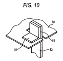
- a power terminal 82 of the brushless motor and a terminal 81 of a print board 80 are connected to each other at a joint 83 by soldering or welding (for example, see JP-A-2004-353537 ).
- the power terminal of the brushless motor is soldered or welded to the terminal of the print board.
- simplification is more needed.
- the driving circuit is provided on a single print board, but there may be a case where the area of the print board needs to be reduced according to a housing for accommodating the brushless motor and the print board therein.
- circuit parts constituting the driving circuit are increased in size to handle a large current (high capacity), and thus the print board is increased in size.
- Print boards having different sizes and shapes are needed according to the capacity of the brushless motor.
- electrical circuit boards need to be provided and managed according to the capacity of the brushless motor.
- the invention has been made in consideration of the above problems, and an object of the invention is to provide an electrical circuit board that simplifies the connection to a motor.
- Another object of the invention is to provide an electrical circuit board that improves convenience when circuit parts are mounted on opposite sides.
- Still another object of the invention is to provide a board device that can allow the electrical circuit board to have the size and shape suitable for the size and shape of a motor and can allow the large motor to be driven using the plurality of driving circuits for the small motors, and provide a board device in which supply and manage of electrical circuit boards are simplified upon mass production of various motor devices or electric pumps.
- Yet still another object of the invention is to provide a motor that can simplify connection to an electrical circuit board.
- Yet still another object of the invention is to provide a motor device and an electric pump that can simplify connection and disconnection to and from an electrical circuit board.
- Yet still another object of the invention is to provide a method of connecting a motor and an electrical circuit board or a board device that can realize ease of manufacturing.
- the present invention is characterized by having the following arrangements.
- the through holes are respectively provided at positions close to the wiring layers, in which the driving current flows. Then, when the conductive bolts are respectively fastened to the motor via the through holes, the bolts are connected to the wiring layers, such that the driving current is supplied to the motor via the bolts. Accordingly, the connection of the electrical circuit board and the motor is simplified. Further, since the bolts fix the electrical circuit board and the motor, a manufacturing process of an electric pump can be simplified, and an electric pump can be reduced in size. In addition, the bolts are easily removed, and thus a time required for replacing and repairing an electrical circuit board and a motor is reduced.
- the wiring layers are provided on opposite sides of the electrical circuit board. Therefore, circuit parts can be easily mounted on opposite sides of the electrical circuit board and connected to the wiring layers.
- the board device has the plurality of electrical circuit boards that are provided in parallel to be spaced at a predetermined interval by the spacers formed of the conductive material.
- the wiring layers of the electrical circuit board spaced apart from each other by the spacers are connected to each other via the spacers.
- the board device can have the plurality of electrical circuit boards that are provided in parallel. Accordingly, when the motor and the electrical circuit board are accommodated in a housing, a plurality of electrical circuit boards having a small area are accommodated in the housing. Further, driving of a high-capacity motor can be performed by connecting a plurality of driving circuits for a low-capacity motor in parallel. Therefore, upon mass production of the motor device or the electric pump, the electrical circuit board can be simply provided and managed.
- the power terminals of the motor are in the form of the nuts. Accordingly, when the conductive bolts are fastened to the nuts via the through holes of the electrical circuit board, the driving current is supplied from the electrical circuit board to the motor via the bolts. Therefore, the connection of the electrical circuit board and the motor is simplified. Further, since the bolts fix the electrical circuit board and the motor, a manufacturing process can be simplified and the electric pump can be reduced in size. In addition, the bolts can be simply removed, and thus the time required for replacing and repairing the electrical circuit board and the motor can be reduced.
- the electrical circuit board is simply connected to the motor by inserting the bolts into the through holes of the electrical circuit board or the board device to be fastened to the nuts of the motor, thereby forming the motor device. Further, the bolts can be simply removed, and thus a time required for replacing and repairing the motor and the electrical circuit board can be reduced.
- the motor and the electrical circuit board are connected to each other by isnerting the bolts into the through holes of the electrical circuit board to be fastened to the nuts of the motor.
- the electric pump has the pump driven by the motor. Accordingly, the connection of the motor and the electrical circuit board are simplified, and thus the electric pump can be simply manufactured.
- the motor and the electrical circuit board are fixed to each other by bolting, a manufacturing process can be simplified, and the electric pump can be reduced in size.
- Fig. 1 is a perspective view of a brushless motor of the embodiment.
- Fig. 2 is a perspective view of a print board on which a driving circuit of the brushless motor is provided.
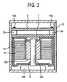
- Fig. 3 is a longitudinal cross-sectional view of an electric pump having the brushless motor.
- Fig. 4 is an enlarged view showing a wiring structure in which the brushless motor and the print board are connected to each other.
- a brushless motor 1 includes a ring-shaped stator coil 11, and a magnet rotor 12 located inside the stator coil 11.
- the magnet rotor 12 has a rotary shaft 12a, and a magnet 12b externally fitted to the rotary shaft 12a.
- the brushless motor 1 is surrounded by a cylindrical case 16 having a bottom.
- the rotary shaft 12a is inserted into both bottoms of the cylinder so as to axially support the cylinder.
- power terminals 4U, 4V and 4W and nuts 3a, 3b, and 3c are provided.
- the nuts 3a, 3b, and 3c are provided at three corners of a square at one end of the case 16, respectively, so as to connect the brushless motor 1 and a print board 5.
- three-phase power terminals 4U, 4V, and 4W in the form of nuts are provided.
- a line connecting the power terminals 4U and 4V and a line connecting the power terminals 4V and 4W are at right angle with the power terminal 4V as a corner.
- the electric pump is configured by connecting the brushless motor 1 and the print board 5, on which the driving circuit is provided by mounting the wiring layers and the circuit parts thereon, by conductive bolts 10a, 10b, 10U, 10V and 10W.
- An operating shaft of a gear pump 14 is connected to the rotary shaft 12a of the brushless motor 1.
- the brushless motor 1, the print board 5 and the gear pump 14 are accommodated in the housing 15.
- the through holes 6a, 6b and 6c are provided at positions where the bolts can be inserted and be fastened to the nuts 3a, 3b and 3c of the brushless motor 1, respectively.
- the through holes 7U, 7V and 7W are provided at positions where the bolts can be inserted and be fastened to the power terminals 4U, 4V and 4W of the brushless motor 1, respectively.
- required wiring patterns including wiring layers 8U, 8V and 8W, through which a three-phase driving current flows, are provided on opposite sides of the print board 5.
- circuit parts such as a FET, a diode, and the like, are mounted on opposite sides of the print board 5, thereby forming the driving circuit.
- the driving circuit generates a three-phase driving current, for example, in a PWM control method.
- the print board 5 is connected to the brushless motor 1 by bolting.
- the bolts 10a, 10b and 10c (not shown) are fastened to the nuts 3a, 3b and 3c provided in the brushless motor 1 via the through holes 6a, 6b and 6c of the print board 5, respectively.
- the rotary shaft 12a is connected to the operating shaft of the gear pump 14.
- the gear pump 14 operates according to the rotation of the rotary shaft 12a, such that a fluid is delivered.
- the print board 5 is provided such that the through holes 7U, 7V and 7W overlap the power terminals 4U, 4V and 4W, respectively.
- the wiring layers 8U, 8V and 8W through which the three-phase driving current flows come into contact with the through holes 7U, 7V and 7W, respectively.
- the wiring layers 8U, 8V and 8W are also provided on a rear surface of the print board 5.
- the bolts 10U, 10V and 10W are inserted into the through holes 7U, 7V and 7W via metal washers 9U, 9V and 9W and fastened to the power terminals 4U, 4V and 4W, respectively. Since the wiring layers 8U, 8V and 8W come into contact with the through holes 7U, 7V and 7W, respectively, the wiring layers 8U, 8V and 8W, the metal washers 9U, 9V and 9W, and the bolts 10U, 10V, and 10W are conducted to one another, respectively.
- the bolts 10U, 10V and 10W are fastened to the power terminals 4U, 4V and 4W, respectively. Accordingly, the wiring layers 8U, 8V and 8W are conducted to the power terminals 4U, 4V and 4W via the metal washers 9U, 9V and 9W and the bolts 10U, 10V and 10W, respectively.
- the power terminals 4U, 4V and 4W of the brushless motor 1 and the wiring layers 8U, 8V and 8W of the print board 5 are conducted to each other by the bolts 10U, 10V and 10W, respectively. Therefore, soldering or welding required for manufacturing a known electric pump is unnecessary, and thus an electric pump is simply manufactured.
- the fastened bolts 10U, 10V and 1OW can be simply removed, after the brushless motor 1 and the print board 5 are connected to each other, the brushless motor 1 and the print board 5 can be disconnected from each other by removing the bolts 10U, 10V and 10W. Accordingly, replacement and repair of the brushless motor 1 and the print board 5 can be simply performed. Therefore, a time required for replacement and repair is reduced.
- circuit parts are mounted on opposite sides of the print board 5 in this embodiment, the circuit parts may be mounted on one side of the print board 5.
- the wiring layers 8U, 8V and 8W come into contact with the through holes 7U, 7V and 7W, respectively.
- the wiring layers 8U, 8V and 8W may not come into contact with the through holes 7U, 7V and 7W, respectively.
- the bolts 10U, 10V and 10W are fastened to the power terminals 4U, 4V and 4W via the metal washers 9U, 9V and 9W and the through holes 7U, 7v and 7W, respectively, the wiring layers 8U, 8V and 8W and the blots 10U, 10V and 10W are connected to each other.
- the brushless motor is used in this embodiment, various motors may be used.
- power terminals are in the form of nuts, and a driving current is supplied from the print board to the power terminals via the bolts. With this configuration, the connection of the motor and the print board is simplified.
- FIG. 5 is a perspective view of a board device, on which a driving circuit for a high-capacity brushless motor having a capacity two times as much as the capacity of a low-capacity brushless motor.
- the board device has two print boards 20a and 20b. As shown in Fig. 5, the print boards 20a and 20b have the same size and shape.
- the print boards 20a and 20b are coaxially provided in parallel around three-phase through holes 21U, 21V and 21W and are spaced apart from each other by conductive spacers 22U, 22V and 22W.
- Power terminals of a high-capacity brushless motor 1a are in the form of nuts.
- the through holes 21U, 21V and 21W are provided at positions where the bolts can be inserted into and fastened to the power terminals.
- Wiring patterns including wiring layers in which a three-phase driving current flows are formed on opposite sides of the print boards 20a and 20b and circuit parts such as a FET, a diode and the like, are mounted thereon, thereby forming driving circuits for a low-capacity brushless motor.
- the wiring layers in which the three-phase driving current flows come into contact with the through holes 21U, 21V and 21W, respectively.
- each of the spacers 22U, 22V and 22W are connected to the wiring layers of the print boards 20a and 20b via a conductive coating material.
- the print boards 20a and 20b are connected in parallel so as to form the board device, and the board device drives the brushless motor having a capacity two times as much as the capacity of a low-capacity brushless motor.
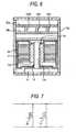
- Fig. 6 is a longitudinal cross-sectional view of an electric pump that uses a high-capacity brushless motor.
- the electric pump is configured by connecting the high-capacity brushless motor 1a, the board device having the two print boards 20a and 20b, and the gear pump 14, and accommodating them in a housing 15a.
- the parts corresponding to the electric pump shown in Fig. 3 are represented by the same reference numerals, and the descriptions thereof will be omitted.
- the two print boards 20a and 20b are provided in parallel to be spaced apart from each other by the spacers 22U, 22V and 22W. Accordingly, an area enough to mount the circuit parts constituting the driving circuit, such as a FET, a diode, and the like, is secured. Therefore, the driving circuits can be provided on the print boards 20a and 20b.
- N-channel power MOSFETs Metal-Oxide-Semiconductor FET
- power MOSFETs 30 and 31 may be controlled at the same time.
- three or more print boards 20a for a low-capacity brushless motor may be connected in parallel by conductive spacers, thereby forming a board device. Accordingly, a high-capacity brushless motor can be driven.
- driving circuits for brushless motors having the same capacity are provided on the print boards 20a and 20b.
- driving circuits for brushless motors having different capacities may be provided, and the conduction between them may be made by conductive spacers.
- the print boards may have different size and shape.
- FIG. 8 is an explanatory view schematically showing essential parts of a hydraulic power steering device of a vehicle.
- the hydraulic power steering device assists steering of a steering mechanism 51 of the vehicle.
- the steering mechanism 51 has a steering wheel 52, a steering shaft 53 that is connected to the steering wheel 52, a pinion 54 that is attached to a front end of the steering shaft 53, a rack shaft 55 that extends in a widthwise direction of the vehicle and is meshed with the pinion, a tie rod 56 that is attached to the rack shaft 55, and a front tire 57 that is attached to the tie rod 56.
- a piston 61 of a power cylinder 60 is connected to the rack shaft 55.
- the power cylinder 60 has a pair of cylinder chambers 60a and 60b that are defined by the piston 61.
- the cylinder chambers 60a and 60b are connected to a hydraulic pressure control valve 63 via oil supply paths 62a and 62b, respectively.
- the hydraulic pressure control valve 63 is connected to a part of an oil circulation path 64.
- a degree of opening of the hydraulic pressure control valve 63 changes according to the direction and size of torque applied to the steering shaft 53 by a steering operation of the steering wheel 52.
- a pump 66 operates by a brushless motor 70 so as to lave a hydraulic oil stored in a reservoir tank 65, circulate through the oil circulation path 64, and return to the reservoir tank 65.
- a vehicle speed sensor 68 detects a rotation speed of the front tire 57.
- the vehicle speed sensor 68 is a magnetic sensor that detects a magnetic metal piece fixed to the front tire 57. Further, the vehicle speed sensor 68 may be an optical sensor that optically detects a hole provided in the front tire 57.
- a vehicle speed signal V that is a detection signal of the vehicle speed sensor 68 is supplied to a driving circuit 69.
- a rotation speed sensor 67 detects a rotation speed of the brushless motor 70 and outputs the detected rotation speed S to the driving circuit 69.
- a steering angle sensor 58 is a rotary encoder that detects a steering angle of the steering wheel 52. The steering angle sensor 58 is attached to the steering shaft 53. The steering angle sensor 58 outputs edge signals S1 and S2 of the rotary encoder to the driving circuit 69.
- the driving circuit 69 generates a driving current for driving the brushless motor 70 on the basis of the vehicle speed signal V supplied from the vehicle speed sensor 68, the rotation speed S supplied from the rotation speed sensor 67, and the edge signals S1 and S2 supplied from the steering angle sensor 58, and output the driving current to the brushless motor 70.
- the driving circuit 69, the brushless motor 70, and the pump 66 correspond to the electric pump of the first embodiment. Further, they may correspond to the electric pump of the second embodiment.
- the hydraulic pressure control valve 63 changes the degree of opening according to the torque transferred to the steering shaft 53, and supplies the hydraulic oil to one of the cylinder chambers 60a and 60b of the power cylinder 60.
- the cylinder 61 moves in the widthwise direction of the vehicle by the hydraulic oil supplied to one of the cylinder chambers 60a and 60b, and assists the movement of the rack shaft 55.
- the driving circuit 69 increases the rotation speed of the brushless motor 70 at the time of a low speed so as to increase an assistance force. Meanwhile, the driving circuit 69 decreases the rotation speed of the brushless motor 70 at the time of a high speed so as to decrease the assistance force. Further, as a steering speed becomes faster on the basis of the edge signals S1 and S2 supplied from the steering angle sensor 58, the driving circuit 69 increases the rotation speed of the brushless motor 70 so as to increase the assistance force.
- Fig. 9 is a block diagram showing the configuration of the driving circuit 69.
- Terminal voltages Vu, Vv, and Vw of the stator coil 11 of U-, V-, and W-phases (see Fig. 3) of the brushless motor 70 are supplied to a rotational position estimation signal generation unit 73.
- the rotational position estimation signal generation unit 73 generates rotational position estimation signals Hu, Hv, and Hw for the individual phases on the basis of the supplied terminal voltages through sampling, and outputs the rotational position estimation signals Hu, Hv, and Hw to a conduction signal generation unit 75. Further, the rotational position estimation signal generation unit 73 outputs a phase signal F indicating a timing of a zero cross point of one phase of the voltages Vu, Vv, and Vw to a PWM control unit 77.
- the conduction signal generation unit 75 generates conduction signals Cu+, Cu-, Cv+, Cv-, Cw+ and Cw- on the basis of the rotational position estimation signals Hu, Hv and Hw for the individual phases supplied from the rotational position estimation signal generation unit 73 and outputs the conduction signals Cu+, Cu-, Cv+, Cv-, Cw+ and Cw- to the PWM control unit 77.
- the conduction signal generation unit 75 has an MPC (Micro Processing Unit) or a logical element.
- a speed control unit 76 determines the rotation speed of the brushless motor 70 on the basis of the rotation speed S supplied from the rotation speed sensor 67, the vehicle speed signal v supplied from the vehicle speed sensor 68, and the edge signals S1 and S2 supplied from the steering angle sensor 58, and outputs a speed control signal Spwm to the PWM control unit 77.
- the PWM control unit 77 generates PWM control signals Du+, Du-, Dv+, Dv-, Dw+ and Dw- for respectively controlling semiconductor switching elements (NPN bipolar transistors) 72u+, 72u-, 72v+, 72v-, 72w+ and 72w- on the basis of the conduction signals Cu+, Cu-, Cv+, Cv-, Cw+ and Cw- supplied from the conduction signal generation unit 75, the speed control signal Spwm supplied from the speed control unit 76, and the phase signal F supplied from the rotational position estimation signal generation unit 73, and supplies the PWM control signals Du+, Du-, Dv+, Dv-, Dw+ and Dw- to a gate drive circuit 78.
- NPN bipolar transistors semiconductor switching elements
- the gate drive circuit 78 turns on/off the semiconductor switching elements 72u+, 72u-, 72v+, 72v-, 72w+ and 72w- on the basis of the PWM control signals Du+, Du-, Dv+, Dv-, Dw+ and Dw- supplied from the PWM control unit 77.
- the semiconductor switching elements 72u+, 72v+ and 72w+ connected to an anode of an in-vehicle battery 49 and the semiconductor switching elements 72u-, 72v- and 72w- connected to a cathode of the in-vehicle battery 49 are connected to each other in series for the U, V and W phases, respectively.
- Connection points between the semiconductor switching elements are respectively connected to the power terminals 4U, 4V and 4W of the brushless motor 70.
- Freewheel diodes are respectively connected to the semiconductor switching elements 72u+, 72u-, 72v+, 72v-, 72w+ and 72w- in inverse parallel connection.
- the semiconductor switching elements 72u+, 72u-, 72v+, 72v-, 72w+ and 72w- are turned on/off by the gate drive circuit 78, and supply a three-phase driving current having a phase difference of 120° to the stator coil 11 of the brushless motor 70.
- the brushless motor 70 generates a rotation magnetic field by the driving current supplied from the switching circuit 79 at the stator coil 11 and rotates the magnet rotor 12.
Landscapes
- Engineering & Computer Science (AREA)
- Microelectronics & Electronic Packaging (AREA)
- Power Engineering (AREA)
- Motor Or Generator Frames (AREA)
Applications Claiming Priority (1)
| Application Number | Priority Date | Filing Date | Title |
|---|---|---|---|
| JP2005365494A JP2007174746A (ja) | 2005-12-19 | 2005-12-19 | 電気回路基板、基板装置、モータ、モータ装置、電動ポンプ及びモータと電気回路基板又は基板装置とを接続する方法 |
Publications (2)
| Publication Number | Publication Date |
|---|---|
| EP1799018A2 true EP1799018A2 (fr) | 2007-06-20 |
| EP1799018A3 EP1799018A3 (fr) | 2009-05-20 |
Family
ID=38006941
Family Applications (1)
| Application Number | Title | Priority Date | Filing Date |
|---|---|---|---|
| EP06026092A Withdrawn EP1799018A3 (fr) | 2005-12-19 | 2006-12-15 | Carte à circuit électrique, dispositif de cartes à circuit, moteur, dispositif avec moteur, pompe électrique et procédé de connexion d'un moteur avec une pompe |
Country Status (3)
| Country | Link |
|---|---|
| US (1) | US20070153448A1 (fr) |
| EP (1) | EP1799018A3 (fr) |
| JP (1) | JP2007174746A (fr) |
Cited By (1)
| Publication number | Priority date | Publication date | Assignee | Title |
|---|---|---|---|---|
| EP3447887A1 (fr) * | 2017-08-25 | 2019-02-27 | JTEKT Corporation | Dispositif de moteur |
Families Citing this family (6)
| Publication number | Priority date | Publication date | Assignee | Title |
|---|---|---|---|---|
| USD570779S1 (en) * | 2006-05-18 | 2008-06-10 | Siemens Aktiengesellschaft | Cast resin coil with attaching bases |
| WO2009055680A1 (fr) * | 2007-10-26 | 2009-04-30 | The Bergquist-Torrington Company | Appareil de retenue de commande de moteur commuté électroniquement |
| JP5446253B2 (ja) * | 2008-12-25 | 2014-03-19 | 日立工機株式会社 | インパクト式ねじ締め装置 |
| US8866356B2 (en) | 2011-09-30 | 2014-10-21 | Mitsubishi Electric Corporation | Motor |
| US10693344B2 (en) | 2014-12-18 | 2020-06-23 | Black & Decker Inc. | Packaging of a control module for a brushless motor |
| KR102284833B1 (ko) * | 2019-12-31 | 2021-08-02 | 효성전기 주식회사 | 모터의 스테이터 |
Family Cites Families (11)
| Publication number | Priority date | Publication date | Assignee | Title |
|---|---|---|---|---|
| US3955122A (en) * | 1974-02-26 | 1976-05-04 | Armor Elevator Company, Inc. | Heat sink mounting for controlled rectifiers |
| JPS614172A (ja) * | 1984-06-18 | 1986-01-10 | ファナック株式会社 | 交流電動機制御盤 |
| JPS63271996A (ja) * | 1987-04-28 | 1988-11-09 | Fanuc Ltd | 大電流用プリント基板 |
| JP2584115B2 (ja) * | 1990-07-31 | 1997-02-19 | オークマ株式会社 | パワー回路配線用プリント基板 |
| US5124883A (en) * | 1990-10-31 | 1992-06-23 | Elcon Products International Company | Printed circuit board power plug contact |
| JPH0624365U (ja) * | 1991-11-29 | 1994-03-29 | 株式会社三協精機製作所 | ブラシレスモータ |
| JPH05151859A (ja) * | 1991-11-29 | 1993-06-18 | Sankyo Seiki Mfg Co Ltd | 基板搭載型スイツチ及びその組付方法 |
| JPH10234158A (ja) * | 1997-02-19 | 1998-09-02 | Tokyo R & D:Kk | 電動モータ |
| KR100496463B1 (ko) * | 1999-08-19 | 2005-06-20 | 가부시기가이샤 산교세이기 세이사꾸쇼 | 브러시레스 모터 |
| DE602004023556D1 (de) * | 2003-05-28 | 2009-11-26 | Aisin Seiki | Elektrisch angetriebene Pumpe |
| JP4001056B2 (ja) * | 2003-05-28 | 2007-10-31 | アイシン精機株式会社 | 電動ポンプ |
-
2005
- 2005-12-19 JP JP2005365494A patent/JP2007174746A/ja active Pending
-
2006
- 2006-12-15 US US11/639,426 patent/US20070153448A1/en not_active Abandoned
- 2006-12-15 EP EP06026092A patent/EP1799018A3/fr not_active Withdrawn
Cited By (3)
| Publication number | Priority date | Publication date | Assignee | Title |
|---|---|---|---|---|
| EP3447887A1 (fr) * | 2017-08-25 | 2019-02-27 | JTEKT Corporation | Dispositif de moteur |
| CN109428449A (zh) * | 2017-08-25 | 2019-03-05 | 株式会社捷太格特 | 马达装置 |
| US10749415B2 (en) | 2017-08-25 | 2020-08-18 | Jtekt Corporation | Motor device |
Also Published As
| Publication number | Publication date |
|---|---|
| JP2007174746A (ja) | 2007-07-05 |
| US20070153448A1 (en) | 2007-07-05 |
| EP1799018A3 (fr) | 2009-05-20 |
Similar Documents
| Publication | Publication Date | Title |
|---|---|---|
| KR100863390B1 (ko) | 모터 구동 회로의 지락 검출 장치 | |
| US8981607B2 (en) | Driving apparatus | |
| JP5574187B2 (ja) | 駆動装置 | |
| JP5725343B2 (ja) | 駆動装置 | |
| CN102255436B (zh) | 电传动装置 | |
| JP6192856B2 (ja) | 制御ユニットおよびこれを用いた電動パワーステアリング装置 | |
| CN102780323B (zh) | 驱动单元 | |
| CN102069842B (zh) | 电机控制装置、电动助力转向装置以及车辆用转向装置 | |
| CN102780320B (zh) | 驱动单元 | |
| US20120286712A1 (en) | Motor drive apparatus | |
| EP2383882A2 (fr) | Dispositif de commande de moteur | |
| EP1799018A2 (fr) | Carte à circuit électrique, dispositif de cartes à circuit, moteur, dispositif avec moteur, pompe électrique et procédé de connexion d'un moteur avec une pompe | |
| JP2015193371A (ja) | 電動パワーステアリング用電子制御装置 | |
| US8896171B2 (en) | Motor drive apparatus having a simplified assembling structure | |
| KR20150032336A (ko) | 전동 모터의 구동 장치 | |
| EP1780094A1 (fr) | Module de commande de dispositif de conduite assistée électrique d'un véhicule | |
| US8767364B2 (en) | Vehicle steering system | |
| JP2014195392A (ja) | モータ駆動用制御装置 | |
| US20220278587A1 (en) | Electronic control unit | |
| US20040200663A1 (en) | Electric motor-driven power steering apparatus | |
| JP2020001667A (ja) | 電動駆動装置、及び電動パワーステアリング装置 | |
| US20190104621A1 (en) | Circuit board and control device | |
| JP2004161118A (ja) | パワーステアリング装置 | |
| JP2012245848A (ja) | 電動パワーステアリング装置 | |
| US20120286594A1 (en) | Motor drive apparatus |
Legal Events
| Date | Code | Title | Description |
|---|---|---|---|
| PUAI | Public reference made under article 153(3) epc to a published international application that has entered the european phase |
Free format text: ORIGINAL CODE: 0009012 |
|
| AK | Designated contracting states |
Kind code of ref document: A2 Designated state(s): AT BE BG CH CY CZ DE DK EE ES FI FR GB GR HU IE IS IT LI LT LU LV MC NL PL PT RO SE SI SK TR |
|
| AX | Request for extension of the european patent |
Extension state: AL BA HR MK YU |
|
| PUAL | Search report despatched |
Free format text: ORIGINAL CODE: 0009013 |
|
| AK | Designated contracting states |
Kind code of ref document: A3 Designated state(s): AT BE BG CH CY CZ DE DK EE ES FI FR GB GR HU IE IS IT LI LT LU LV MC NL PL PT RO SE SI SK TR |
|
| AX | Request for extension of the european patent |
Extension state: AL BA HR MK RS |
|
| 17P | Request for examination filed |
Effective date: 20091120 |
|
| AKX | Designation fees paid |
Designated state(s): DE FR |
|
| STAA | Information on the status of an ep patent application or granted ep patent |
Free format text: STATUS: THE APPLICATION HAS BEEN WITHDRAWN |
|
| 18W | Application withdrawn |
Effective date: 20110913 |