EP1799379B1 - Seitenabdichtung eines zwischen zwei giessrollen einer bandgiessmaschine gebildeten giessspaltes - Google Patents
Seitenabdichtung eines zwischen zwei giessrollen einer bandgiessmaschine gebildeten giessspaltes Download PDFInfo
- Publication number
- EP1799379B1 EP1799379B1 EP05786328A EP05786328A EP1799379B1 EP 1799379 B1 EP1799379 B1 EP 1799379B1 EP 05786328 A EP05786328 A EP 05786328A EP 05786328 A EP05786328 A EP 05786328A EP 1799379 B1 EP1799379 B1 EP 1799379B1
- Authority
- EP
- European Patent Office
- Prior art keywords
- casting
- lateral seal
- seal according
- openings
- snout
- Prior art date
- Legal status (The legal status is an assumption and is not a legal conclusion. Google has not performed a legal analysis and makes no representation as to the accuracy of the status listed.)
- Expired - Lifetime
Links
Images



Classifications
-
- B—PERFORMING OPERATIONS; TRANSPORTING
- B22—CASTING; POWDER METALLURGY
- B22D—CASTING OF METALS; CASTING OF OTHER SUBSTANCES BY THE SAME PROCESSES OR DEVICES
- B22D11/00—Continuous casting of metals, i.e. casting in indefinite lengths
- B22D11/06—Continuous casting of metals, i.e. casting in indefinite lengths into moulds with travelling walls, e.g. with rolls, plates, belts, caterpillars
- B22D11/0637—Accessories therefor
- B22D11/0648—Casting surfaces
- B22D11/066—Side dams
-
- B—PERFORMING OPERATIONS; TRANSPORTING
- B22—CASTING; POWDER METALLURGY
- B22D—CASTING OF METALS; CASTING OF OTHER SUBSTANCES BY THE SAME PROCESSES OR DEVICES
- B22D11/00—Continuous casting of metals, i.e. casting in indefinite lengths
- B22D11/06—Continuous casting of metals, i.e. casting in indefinite lengths into moulds with travelling walls, e.g. with rolls, plates, belts, caterpillars
- B22D11/0637—Accessories therefor
- B22D11/068—Accessories therefor for cooling the cast product during its passage through the mould surfaces
- B22D11/0682—Accessories therefor for cooling the cast product during its passage through the mould surfaces by cooling the casting wheel
-
- B—PERFORMING OPERATIONS; TRANSPORTING
- B22—CASTING; POWDER METALLURGY
- B22D—CASTING OF METALS; CASTING OF OTHER SUBSTANCES BY THE SAME PROCESSES OR DEVICES
- B22D11/00—Continuous casting of metals, i.e. casting in indefinite lengths
- B22D11/12—Accessories for subsequent treating or working cast stock in situ
- B22D11/128—Accessories for subsequent treating or working cast stock in situ for removing
- B22D11/1287—Rolls; Lubricating, cooling or heating rolls while in use
-
- B—PERFORMING OPERATIONS; TRANSPORTING
- B22—CASTING; POWDER METALLURGY
- B22D—CASTING OF METALS; CASTING OF OTHER SUBSTANCES BY THE SAME PROCESSES OR DEVICES
- B22D15/00—Casting using a mould or core of which a part significant to the process is of high thermal conductivity, e.g. chill casting; Moulds or accessories specially adapted therefor
- B22D15/005—Casting using a mould or core of which a part significant to the process is of high thermal conductivity, e.g. chill casting; Moulds or accessories specially adapted therefor of rolls, wheels or the like
Definitions
- the invention relates to a side seal of a casting gap formed between two casting rolls of a strip casting machine according to the preamble of claim 1.
- a side seal of this kind is in the WO 2004/033130 .
- Fig. 7 to 9 disclosed. It comprises a wetted first part of a refractory material and a second part of a refractory metal associated with the end faces of the casting rolls.
- the second part has a kind of "snout shape" with two legs extending along the casting-roll end faces and converging below a so-called kiss point to a common area, between which the first part protrudes from above.
- the first part consists of one refractory material, the second of a high-temperature resistant alloy, a gray cast iron or a high-strength steel.
- the two parts are provided with a coating.
- the present invention has for its object to further improve a side seal of the type mentioned not only in terms of wear resistance and durability but also in terms of heat loss, to avoid unwanted solidification in this area.
- the heat loss in the side seals is largely prevented or minimized, so that even when using a protected metal plate in the wetted area no solidification.
- the wetted part 12 can be kept very hot and preheated very much (900-1300 ° C).
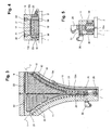
- a first embodiment of a side seal 10 is shown for a roll-strip casting machine, which is provided for the lateral sealing of a casting gap formed between two casting rolls.
- Two arranged on both faces of the casting rolls side seals 10 (also called narrow side parts) limit the casting gap in its length.
- the casting rolls are in Fig. 3, 4 and 5 indicated and labeled 1, 2.
- the side seal 10 is housed in a holding frame 11, which is operatively connected to a not apparent from the drawing adjusting device.
- the holding frame 11 is adjustable together with the side seal 10 in the longitudinal direction of the casting rolls 1, 2, whereby the side seal 10 with its sealing side 10 'at the end faces of the casting rolls 1, 2 can be positioned.
- the side seal 10 comprises a so-called wetted first part 12, which in the embodiment according to Fig. 1 to 5 consists of a refractory material, and a front sides of the casting rolls 1, 2 associated second part 13, which is made of a preferably high temperature resistant metal. Both parts 12, 13 are preferably provided with a suitable coating.
- the second part 13 has a kind of "snout shape" with two limbs 13s extending along the casting-roll end faces and converging below a so-called kiss point to a common middle region 13m (see in particular the right-hand half of FIG Fig. 3 ).
- the first part 12 protrudes from above between the two legs 13s of the second part 13 and is centered therethrough, wherein it overlaps the casting rollers end faces radially by an amount of 1 to 3 mm and thus their edge region covers.
- the first part 12 is held in an enclosing plate 15 (FIG. 2) which is applied to the second part 13 and forms a kind of cassette with it.
- Fig. 2 being positioned on the rear side remote from the sealing side 10 'by means of spacers 16 in the depth opposite the enclosing plate 15, and by means of an insulating plate 17 (FIG. Fig. 2 ) is disconnected.
- the first part 12 is not only to the rear, but along the entire contour with an insulation 18, 19 (FIG. Fig. 2 . 3 and 4 ), which also separates the two parts 12, 13 from each other, and which for protection, in order to avoid crushing, in the depth opposite the sealing side 10 'of the parts 12, 13 stands back slightly, to a part 13 projecting, the Isolation centering nose 13 'is provided.
- the cassette-type side seal 10 is inserted from the front into the holding frame, such that the enclosing plate 15 and the snout-shaped second part 13 abut the rear on a base surface of the holding frame 11 provided with cooling channels 20, 21 for a cooling medium, preferably cooling water.
- the cooling channels 20, 21 are connected to a cooling water inlet 26 (FIG. Fig. 2 . 3 and 5 ) on the one hand and via further, upper and side holding frame cooling channels 22, 23 to a cooling water outlet 25 (FIG. Fig. 2 and 3 ) on the other hand connected.
- the schnauzförmige second part 13 is thus directly cooled from behind.
- the snout-shaped second part 13 is provided with a number of outlet openings 30, which are preferably uniformly distributed along the casting roller edges and directed against the end faces of the casting rolls 1, 2, via distribution channels 31, 32 to a gas or lubricant source 35 (FIG. Fig. 1 . 3 and 5 ) are connected.
- a gas or lubricant source 35 (FIG. Fig. 1 . 3 and 5 ) are connected.
- Inert gas crude oil or other suitable materials such as grease or graphite-containing sizing can be distributed over the sealing parts along the casting roll end faces or edges and form a bearing layer with a very small thickness (gap 0.01-0.03 mm).
- the snout-shaped second part 13 i.e., the front side of the sealing parts
- a coating which can absorb the change in length of the casting rolls during casting instead, however, a heat- and abrasion-resistant film with appropriately punched holes for the outlet openings 30 can be applied to the second part 13.
- the side seals especially if they refractory sealing plates or sealing plate parts as the first part 12 after Fig. 1 to 5 include preheated before pouring.
- this region remains substantially temperature-moderately below the high required temperature of 800-1300 ° C. of the first wetted part 12.
- the outlet openings 30 in the schnauzförmigen second part 13 are made as small holes to allow hydrodynamic storage. However, it could also be extending in the circumferential direction of the casting rolls slots.
- a second embodiment of a side seal 10a is shown.
- the constant parts of this side seal 10a are denoted by the same reference numerals as in FIG Fig. 1 to 5 ,
- the side seal 10a again comprises a wetted first part 12a and a schnauzförmigen second part 13a, which abut the rear of a metal plate 37, wherein the plate 37 is positioned over spacers 16a opposite a Umschliessungsblech 15 in depth and separated by an insulating plate 17a thereof ,
- the side seal 10a is thus again formed like a cassette which can be inserted from the front into the holding frame 11.
- the wetted first part 12a is made in this variant of a high temperature resistant metal and again along the entire contour with the insulation 18, 19, so that the two parts 12a, 13a centered on each other, but are separated from each other.
- the snout-shaped second part 13a has, in addition to the outlet openings 30 distributed along the casting-roller edges, also in the central area 13m further outlet openings 40a (FIG. Fig. 6 and 10 ).
- the metal first part 12a which is preferably coated with a ceramic coating, is provided with a number of distributed over its surface outlet openings 40, which together with the additional outlet openings 40a in the central region 13m of the second part to a separate gas or Gleitffenetti 45 (inert gas, oil, sizing, etc.) are connected, via a central vertical connection channel 44 and from this branching horizontal distribution channels 43, which in the rear plate 37 are made.
- a film can be formed on the sealing side 10a '.
- the outlet openings 40 provided in the wetted first part 12a can have different sizes over the height in order to take into account the ferrostatic pressure difference.
- a side seal 10b comprising a snout-shaped part 13b made of a high-temperature resistant metal, which in turn is provided with the outlet openings 30 distributed along the roller edges and abuts a rear metal plate 37b together with the wetted first part 12b.
- the wetted portion 12b is formed by a high temperature resistant metal plate 50 having a number of apertures 51 distributed throughout the surface filled with a refractory or fiber-like material 52. It is noted that the expansion coefficients are chosen so that no gaps can arise. This embodiment allows to reduce the metal content of the wetted first part 12b to 25-50%.
- the metal plate which in turn Austrittsöffnunen 54 for a medium such as gas, oil, sizing, etc. are applied independently of the outlet openings 30 of the snout-shaped part 13 b, including a separate source 45 and in the rear plate 37b made connection channels or connection spaces 55, 56 are present.
- Austrittsöffnunen 54 for a medium such as gas, oil, sizing, etc.
- the wetted first part 12b can be provided with an insulating protective film.
- FIG. 15 and 16 illustrated side seal 10c substantially corresponds to the side seal 10b described above.
- the first part 12c in turn comprises the metal plate 50 with the larger openings 51, in contrast to the variant according to Fig. 11 to 14
- the openings 51 are not filled alone, but the metal plate 50 is molded with a refractory, projecting to the sealing side material, so that actually a refractory plate 59 is formed with projecting into the openings 51 cylindrical protrusions 60.
- the sealing side is also coated here.
- the refractory material is held together by the metal plate 50, ie the metal plate counteracts the formation of cracks in the refractory material.
- FIGS. 17 and 18 a side seal 10d is shown which differs from that of FIG Fig. 11 to 14 characterized in that the first, wetted part 12d (or its metal plate 50d, the openings 51d are filled with a refractory material 52d) with a central, projecting and between the casting rolls 1, 2 protruding nose 63 is provided, the depth of this Nose 63 decreases from top to bottom. Through this nose 63, the hot metal melt supplied by the casting tube is forced into the edge region of the casting rolls 1, 2 in order to eliminate parasitic solidification.
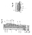
- FIGS. 19 and 20 shown side seal 10e corresponds essentially to the embodiment Fig. 15 and 16
- the first wetted part 12e again has a nose 63e projecting between the casting rolls 1, 2, the shape of which follows that of the nose FIGS. 17 and 18 but is associated with the refractory plate 59e.
- All the embodiments described above are characterized by the snout-shaped part 13, in which the wetted part 12 is held centered by means of an insulation 18 located therebetween.
- the wetted part 12 can be kept very hot and preheated very much (900-1300 ° C).
- the cassette construction of the side seals of the invention allows various advantageous interchangeable combinations of refractory and metal in the wetted area, with 25-50% metal and 75-50% refractory, with the refractory material being advantageously held together by cracks.
- the side seals according to the invention are being revised or need only be partially renewed. This makes it possible to allow longer casting cycles and to reuse the sealing parts.
- the cassette-like side seals could also be used from above in a correspondingly designed housing or in an open-topped holding frame.
- the side seals according to the invention could also be installed directly in the holding frame without the enclosing plate, i.
- the cassette construction is not absolutely necessary.
Landscapes
- Engineering & Computer Science (AREA)
- Mechanical Engineering (AREA)
- Continuous Casting (AREA)
- Gasket Seals (AREA)
- Rolls And Other Rotary Bodies (AREA)
- Lining Or Joining Of Plastics Or The Like (AREA)
- Machines For Manufacturing Corrugated Board In Mechanical Paper-Making Processes (AREA)
Description
- Die Erfindung betrifft eine Seitenabdichtung eines zwischen zwei Giessrollen einer Bandgiessmaschine gebildeten Giessspaltes gemäss dem Oberbegriff des Anspruches 1.
- Eine Seitenabdichtung dieser Art ist in der
WO 2004/033130 ,Fig. 7 bis 9 , offenbart. Sie umfasst einen benetzten ersten Teil aus einem feuerfesten Material sowie einen den Stirnseiten der Giessrollen zugeordneten zweiten Teil aus einem hochtemperaturbeständigen Metall. Der zweite Teil weist eine Art "Schnauzform" mit zwei sich entlang der Giessrollen-Stirnseiten erstreckenden und unten oberhalb eines sogenannten Kusspunktes zu einem gemeinsamen Bereich zusammenlaufenden Schenkeln auf, zwischen welche der erste Teil von oben hineinragt. Der erste Teil besteht aus einem feuerfesten Material, der zweite aus einer hochtemperaturbeständigen Legierung, einem Grauguss oder einem hochfesten Stahl. Die beiden Teile sind mit einer Beschichtung versehen. - Der vorliegenden Erfindung liegt die Aufgabe zugrunde, eine Seitenabdichtung der eingangs genannten Art nicht nur bezüglich der Verschleissresistenz und der Haltbarkeit sondern auch was Wärmeverluste anbelangt weiter zu verbessern, um unerwünschte Erstarrungen in diesem Bereich zu vermeiden.
- Diese Aufgabe wird erfindungsgemäss durch eine Seitenabdichtung mit den Merkmalen des Anspruches 1 gelöst.
- Weitere bevorzugte Ausgestaltungen der erfindungsgemässen Seitenabdichtung bilden den Gegenstand der abhängigen Ansprüche.
- Dadurch, dass zwischen dem ersten und dem zweiten Teil eine die beiden Teile im Wesentlichen voneinander trennende Isolationsschicht eingebracht ist, wird der Wärmeverlust bei den Seitenabdichtungen weitgehend verhindert oder minimiert, so dass auch bei Verwendung einer geschützten Metallplatte im benetzten Bereich keine Erstarrungen entstehen. Der benetzte Teil 12 kann sehr heiss gehalten und sehr stark vorgeheizt werden (900-1300°C).
- Die Erfindung wird nachfolgend anhand der Zeichnung näher erläutert. Es zeigen:
- Fig. 1
- ein erstes Ausführungsbeispiel einer erfindungsgemässen Seitenabdichtung in Frontansicht;
- Fig. 2
- einen Schnitt nach Linie II-II in
Fig. 1 ; - Fig. 3
- in der linken Hälfte einen Schnitt nach Linie IIIA-IIIA und in der rechten Hälfte einen Schnitt nach Linie IIIB-IIIB in
Fig. 2 ; - Fig. 4
- einen Schnitt nach Linie IV-IV in
Fig. 1 ; - Fig. 5
- einen Schnitt nach Linie V-V in
Fig. 1 ; - Fig. 6
- ein zweites Ausführungsbeispiel einer erfindungsgemässen Seitenabdichtung in Frontansicht;
- Fig. 7
- einen Schnitt nach Linie VII-VII in
Fig. 6 ; - Fig. 8
- in der linken Hälfte einen Schnitt nach Linie VIIIA-VIIIA und in der rechten Hälfte einen Schnitt nach Linie VIIIB-VIIIB in
Fig. 7 ; - Fig. 9
- einen Schnitt nach Linie IX-IX in
Fig. 6 ; - Fig. 10
- einen Schnitt nach Linie X-X in
Fig. 6 ; - Fig. 11
- ein drittes Ausführungsbeispiel einer erfindungsgemässen Seitenabdichtung in Frontansicht;
- Fig. 12
- einen Schnitt nach Linie XII-XII in
Fig. 11 ; - Fig. 13
- in der linken Hälfte einen Schnitt nach Linie XIIIA-XIIIA und in der rechten Hälfte einen Schnitt nach Linie XIIIB-XIIIB in
Fig. 12 ; - Fig. 14
- einen Schnitt nach Linie XIV-XIV in
Fig. 11 ; - Fig. 15
- ein viertes Ausführungsbeispiel einer erfindungsgemässen Seitenabdichtung im vertikalen Schnitt, der
Fig. 12 entsprechend; - Fig. 16
- die Seitenabdichtung nach
Fig. 15 in einem horizontalen Schnitt, derFig. 14 entsprechend; - Fig. 17
- ein fünftes Ausführungsbeispiel einer erfindungsgemässen Seitenabdichtung im vertikalen Schnitt;
- Fig. 18
- die Seitenabdichtung nach
Fig. 17 in einem horizontalen Schnitt; - Fig. 19
- ein sechstes Ausführungsbeispiel einer erfindungsgemässen Seitenabdichtung im vertikalen Schnitt; und
- Fig. 20
- die Seitenabdichtung nach
Fig. 19 in einem horizontalen Schnitt. - In
Fig.1 bis 5 ist ein erstes Ausführungsbeispiel einer Seitenabdichtung 10 für eine Rollen-Bandgiessmaschine gezeigt, die zur seitlichen Abdichtung eines zwischen zwei Giessrollen gebildeten Giessspaltes vorgesehen ist. Zwei zu beiden Stirnseiten der Giessrollen angeordnete Seitenabdichtungen 10 (auch Schmalseitenteile genannt) begrenzen den Giessspalt in seiner Länge. Die Giessrollen sind inFig. 3, 4 und 5 angedeutet und mit 1, 2 bezeichnet. - Die Seitenabdichtung 10 ist in einem Halterahmen 11 untergebracht, der mit einer aus der Zeichnung nicht ersichtlichen Anstellvorrichtung wirkverbunden ist. Der Halterahmen 11 ist mitsamt der Seitenabdichtung 10 in Längsrichtung der Giessrollen 1, 2 verstellbar, wodurch die Seitenabdichtung 10 mit ihrer Abdichtseite 10' an Stirnseiten der Giessrollen 1, 2 positionierbar ist.
- Die Seitenabdichtung 10 umfasst einen sogenannten benetzten ersten Teil 12, der bei der Ausführungsvariante nach
Fig. 1 bis 5 aus einem feuerfesten Material besteht, sowie einen den Stirnseiten der Giessrollen 1, 2 zugeordneten zweiten Teil 13, der aus einem vorzugsweise hochtemperaturbeständigen Metall angefertigt ist. Beide Teile 12, 13 sind vorzugsweise mit einer geeigneten Beschichtung versehen. Der zweite Teil 13 weist eine Art "Schnauzform" mit zwei sich entlang der Giessrollen-Stirnseiten erstreckenden und unten oberhalb eines sogenannten Kusspunktes zu einem gemeinsamen mittleren Bereich 13m zusammenlaufenden Schenkeln 13s auf (vgl. insbesondere die rechte Hälfte derFig. 3 ). Der erste Teil 12 ragt von oben zwischen die beiden Schenkel 13s des zweiten Teiles 13 hinein und wird durch diese zentriert, wobei er die Giessrollen-Stirnseiten radial um einen Betrag von 1 bis 3 mm überlappt und somit ihren Kantenbereich abdeckt. Gehalten wird der erste Teil.12 in einem auf den zweiten Teil 13 aufgebrachten und mit diesem zusammen eine Art Kassette bildenden Umschliessungsblech 15 (Fig. 2 ), wobei er auf der der Abdichtseite 10' abgewandten hinteren Seite über Distanzstücke 16 in der Tiefe gegenüber dem Umschliessungsblech 15 positioniert ist und von diesem durch eine Isolationsplatte 17 (Fig. 2 ) getrennt ist. - Erfindungsgemäss ist der erste Teil 12 nicht nur nach hinten, sondern entlang der ganzen Kontur mit einer Isolation 18, 19 (
Fig. 2 ,3 und 4 ) versehen, die auch die beiden Teile 12, 13 voneinander trennt, und die zum Schutz, um ein Zerdrücken zu vermeiden, in der Tiefe gegenüber der Abdichtseite 10' der Teile 12, .13 etwas zurücksteht, dazu eine beim Teil 13 vorstehende, die Isolation zentrierende Nase 13' vorgesehen ist. - Die kassettenartige Seitenabdichtung 10 wird von vorne in den Halterahmen eingelegt, derart, dass der Umschliessungsblech 15 sowie der schnauzförmige zweite Teil 13 hinten auf einer mit Kühlkanälen 20, 21 für ein Kühlmedium, vorzugsweise Kühlwasser, versehenen Grundfläche des Halterahmens 11 anliegt. Die Kühlkanäle 20, 21 sind an einen Kühlwasser-Zulauf 26 (
Fig. 2 ,3 und 5 ) einerseits und über weitere, obere und seitliche Halterahmen-Kühlkanäle 22, 23 an einen Kühlwasser-Ablauf 25 (Fig. 2 und3 ) anderseits angeschlossen. Der schnauzförmige zweite Teil 13 wird somit von hinten direkt gekühlt. - Der schnauzförmige zweite Teil 13 ist erfindungsgemäss mit einer Anzahl von entlang der Giessrollenkanten vorzugsweise gleichmässig verteilten, gegen die Stirnseiten der Giessrollen 1, 2 gerichteten Austrittsöffnungen 30 versehen, die über Verteilungskanäle 31, 32 an eine Gas- bzw. Gleitmittelquelle 35 (
Fig. 1 ,3 und 5 ) angeschlossen sind. Durch die Austrittsöffnungen 30 kann Inertgas, Rohöl oder andere geeignete Materialien wie Fett oder graphithaltige Schlichte über die Dichtpartien entlang der Giessrollen-Stirnseiten bzw. Kanten verteilt werden und eine Lagerschicht mit einer sehr kleinen Dicke (Spalt 0,01-0,03 mm) bilden. - Wie bereits erwähnt, ist der schnauzförmige zweite Teil 13 (d.h. die Frontseite der Dichtpartien) mit einem Belag beschichtet, der die Längenveränderung der Giessrollen beim Angiessen auffangen kann. Statt dessen kann aber auch eine hitze- und abriebbeständige Folie mit entsprechend ausgestanzten Löchern für die Austrittsöffnungen 30 auf den zweiten Teil 13 aufgebracht werden.
- Bekanntlich werden die Seitenabdichtungen, insbesondere wenn sie feuerfeste Dichtplatten oder Dichtplattenteile wie den ersten Teil 12 nach
Fig. 1 bis 5 beinhalten, vor dem Giessen vorgeheizt. Die erfindungsgemässe Seitenabdichtung 10 mit der zwischen dem ersten und dem zweiten Teil 12, 13 eingebrachten und die beiden Teile 12, 13 voneinander trennende Isolation 18 bringt den Vorteil mit sich, dass nicht wie bisher der Grossteil der Wärme über die Giessrollenstirnseiten abgeleitet wird. - Durch die direkte Auflage des schnauzförmigen zweiten Teils 13 auf den gekühlten Halterahmen 11 bleibt dieser Bereich temperaturmässig substantiell unter der hohen benötigten Temperatur von 800-1300°C des ersten benetzten Teiles 12.
- Die Austrittsöffnungen 30 im schnauzförmigen zweiten Teil 13 werden als kleine Bohrungen angefertigt, um eine hydrodynamische Lagerung zu ermöglichen. Es könnte sich jedoch auch um sich in Umfangsrichtung der Giessrollen erstreckende Schlitze handeln.
- In
Fig. 6 bis 10 ist ein zweites Ausführungsbeispiel einer Seitenabdichtung 10a dargestellt. Die gleichbleibenden Teile dieser Seitenabdichtung 10a sind mit den gleichen Bezugsziffern bezeichnet wie inFig. 1 bis 5 . Die Seitenabdichtung 10a umfasst wiederum einen benetzten ersten Teil 12a sowie einen schnauzförmigen zweiten Teil 13a, die hinten an einer metallenen Platte 37 anliegen, wobei die Platte 37 über Distanzstücke 16a gegenüber einem Umschliessungsblech 15 in der Tiefe positioniert und mittels einer Isolationsplatte 17a von diesem getrennt ist. Die Seitenabdichtung 10a ist somit wiederum wie eine in den Halterahmen 11 von vorne einlegbare Kassette ausgebildet. (Allerdings könnte auch hier mit Vorteil der schnauzförmige, aus einem hochtemperaturbeständigen Metall bestehende zweite Teil direkt am gekühlten Halterahmen 11 anliegen.) Der benetzte erste Teil 12a ist bei dieser Variante aus einem hochtemperaturbeständigen Metall angefertigt und wiederum entlang der ganzen Kontur mit der Isolation 18, 19 versehen, so dass die beiden Teile 12a, 13a zueinander zentriert, jedoch voneinander getrennt sind. - Der schnauzförmige zweite Teil 13a weist zusätzlich zu den entlang den Giessrollenkanten verteilten Austrittsöffnungen 30 auch im mittleren Bereich 13m weitere Austrittsöffnungen 40a (
Fig. 6 und10 ). Aber auch der metallene erste Teil 12a, der vorzugsweise mit einem Keramikauftrag beschichtet ist, ist mit einer Anzahl von über seine Fläche verteilten Austrittsöffnungen 40 versehen, die zusammen mit den zusätzlichen Austrittsöffnungen 40a im mittleren Bereich 13m des zweiten Teiles an eine separate Gas- bzw. Gleitmittelquelle 45 (Inertgas, Oel, Schlichte etc.) angeschlossen sind, und zwar über einen zentralen vertikalen Anschlusskanal 44 und von diesem abzweigende horizontale Verteilungskanäle 43, die in der hinteren Platte 37 angefertigt sind. Somit kann auf der Abdichtseite 10a' ein Film gebildet werden. - Die im benetzten ersten Teil 12a vorgesehenen Austrittsöffnungen 40 können über die Höhe unterschiedliche Grösse aufweisen, um dem ferrostatischen Druckunterschied Rechnung zu tragen.
- In
Fig. 11 bis 14 wird eine weitere Ausführungsform einer Seitenabdichtung 10b gezeigt, die einen aus einem hochtemperaturbeständigen Metall bestehenden schnauzförmigen Teil 13b aufweist, der wiederum mit den entlang der Rollenkanten verteilten Austrittsöffnungen 30 versehen ist und zusammen mit dem benetzten ersten Teil 12b an einer hinteren metallenen Platte 37b anliegt. Der benetzte Teil 12b ist durch eine aus einem hochtemperaturbeständigen Metall bestehende Platte 50 gebildet, die eine Anzahl von über die Gesamtfläche verteilten Öffnungen 51 aufweist, die mit einem feuerfesten oder faserähnlichen Material 52 ausgefüllt sind. Dabei wird beachtet, dass die Ausdehnungskoeffizienten so gewählt werden, dass keine Spalten entstehen können. Diese Ausführung erlaubt, den metallenen Anteil des benetzten ersten Teiles 12b auf 25-50% zu reduzieren. - Um die Öffnungen 51 sind in der Metallplatte 50 kleine Bohrungen angefertigt, die wiederum Austrittsöffnunen 54 für ein Medium wie Gas, Oel, Schlichte etc. bilden und unabhängig von den Austrittsöffnungen 30 des schnauzförmigen Teils 13b beaufschlagt werden, wozu eine separate Quelle 45 sowie in der hinteren Platte 37b angefertigte Anschlusskanäle bzw. Anschlussräume 55, 56 vorhanden sind. Somit kann wiederum der benetzte erste Teil 12b mit einem isolierenden Schutzfilm versehen werden.
- Eine in
Fig. 15 und16 dargestellte Seitenabdichtung 10c entspricht im wesentlichen der vorstehend beschriebenen Seitenabdichtung 10b. Der erste Teil 12c umfasst wiederum die Metallplatte 50 mit den grösseren Öffnungen 51, im Unterschied zu der Variante nachFig. 11 bis 14 sind jedoch nicht die Öffnungen 51 allein ausgefüllt, sondern die Metallplatte 50 ist mit einem feuerfesten, zur Abdichtseite überstehenden Material eingegossen, so dass eigentlich eine feuerfeste Platte 59 mit in die Öffnungen 51 hineinragenden zylindrischen Vorsprüngen 60 gebildet wird. Dadurch wird die Metallplatte 50 weiter temperaturmässig geschont und die Wärmeabfuhr reduziert. Die Abdichtseite wird auch hier beschichtet. Das feuerfeste Material wird durch die Metallplatte 50 zusammengehalten, d.h. die Metallplatte wirkt der Entstehung von Rissen im feuerfesten Material entgegen. - In
Fig. 17 und 18 wird eine Seitenabdichtung 10d gezeigt, die sich von derjenigen nachFig. 11 bis 14 dadurch unterscheidet, dass der erste, benetzte Teil 12d (bzw. seine Metallplatte 50d, deren Öffnungen 51d mit einem feuerfesten Material 52d ausgefüllt sind) mit einer zentralen, vorstehenden und zwischen die Giessrollen 1, 2 hineinragenden Nase 63 versehen ist, wobei die Tiefe dieser Nase 63 von oben nach unten abnimmt. Durch diese Nase 63 wird die vom Giessrohr zugeführte heisse Metallschmelze in den Kantenbereich der Giessrollen 1, 2 gedrängt, um parasitäre Erstarrungen zu eliminieren. - Eine in
Fig. 19 und 20 dargestellte Seitenabdichtung 10e entspricht im wesentlichen der Ausführung nachFig. 15 und16 , der erste, benetzte Teil 12e weist jedoch wiederum eine zwischen die Giessrollen 1, 2 hineinragende Nase 63e, die in ihrer Form derjenigen nachFig. 17 und 18 entspricht, jedoch der feuerfesten Platte 59e zugeordnet ist. - Alle vorstehend beschriebenen Ausführungsvarianten zeichnen sich durch den schnauzförmigen Teil 13 auf, in dem der benetzte Teil 12 über eine dazwischenliegende Isolation 18 zentriert gehalten wird. Der benetzte Teil 12 kann sehr heiss gehalten und sehr stark vorgeheizt werden (900-1300°C).
- Dank der Gas- bzw. Gleitmittel-Beaufschlagung im Dichtbereich und durch die abriebfeste Auflage des schnauzförmigen Teiles wird der Verschleiss erheblich reduziert oder sogar weitgehend vermieden, wodurch die Haltbarkeit der Seitenabdichtungen wesentlich verlängert wird. Der Kassettenaufbau der erfindungsgemässen Seitenabdichtungen erlaubt verschiedene vorteilhafte, austauschbare Kombinationen von feuerfestem Material und Metall im benetzten Bereich, mit 25-50% Metall und 75-50% feuerfesten Materials, wobei das feuerfeste Material vorteilhaft bei Rissen zusammengehalten wird. Die erfindungsgemässen Seitenabdichtungen werden überarbeitet oder brauchen nur partiell erneuert zu werden. Damit ist es möglich, längere Giesszyklen zuzulassen und die Abdichtungsteile wiederzuverwenden.
- Statt von vorne könnten die kassettenartigen Seitenabdichtungen auch von oben in ein entsprechend ausgebildetes Gehäuse bzw. in einen oben offenen Halterahmen einsetzbar sein. Allerdings könnten die erfindungsgemässen Seitenabdichtungen auch ohne den Umschliessungsblech direkt in den Halterahmen eingebaut werden, d.h. der Kassettenaufbau ist nicht zwingend notwendig.
Claims (14)
- Seitenabdichtung eines zwischen zwei Giessrollen (1, 2) einer Bandgiessmaschine gebildeten Giessspaltes, die stirnseitig an die Giessrollen (1, 2) positionierbar ist, und die einen ersten, benetzten Teil (12, 12a, 12b, 12c, 12d, 12e) sowie einen den Stirnseiten der Giessrollen (1, 2) zugeordneten zweiten Teil (13, 13a, 13b) aufweist, wobei der zweite Teil (13, 13a, 13b) eine Art "Schnauzform" mit zwei sich entlang der Giessrollen-Stirnseiten erstreckenden und unten oberhalb eines sogenannten Kusspunktes zu einem gemeinsamen Bereich (13m) zusammenlaufenden Schenkeln (13s) aufweist, zwischen welche der erste Teil (12, 12a, 12b, 12c, 12d, 12e) von oben hineinragt, dadurch gekennzeichnet, dass zwischen dem ersten und dem zweiten Teil eine die beiden Teile (12, 12a, 12b, 12c, 12d, 12e, 13, 13a, 13b) voneinander trennende Isolationsschicht (18) eingebracht ist.
- Seitenabdichtung nach Anspruch 1, dadurch gekennzeichnet, dass der zweite, aus einem vorzugsweise hochtemperaturbeständigen Metall bestehende schnauzförmige Teil (12, 12a, 12b, 12c, 12d, 12e) eine Anzahl von an eine Gas- bzw. Gleitmittelquelle (35) angeschlossenen, gegen die Giessrollen-Stirnseiten gerichteten und entlang der Giessrollenkanten verteilten Austrittsöffnungen (30) für Inertgas oder Gleitmittel wie Oel, Fett oder graphithaltige Schlichte versehen ist.
- Seitenabdichtung nach Anspruch 2, dadurch gekennzeichnet, dass der erste benetzte Teil (12a, 12b, 12c, 12d, 12e) zumindest teilweise aus einem hochtemperaturbeständigen Metall besteht und mit einer Anzahl von über seine Gesamtfläche verteilten, gegen die Abdichtseite gerichteten und an eine weitere Gas- bzw. Gleitmittelquelle (45) angeschlossenen Austrittsöffnungen (40, 54) für Inertgas oder Gleitmittel wie Oel, Fett oder graphithaltige Schlichte versehen ist.
- Seitenabdichtung nach Anspruch 3, dadurch gekennzeichnet, dass der erste, benetzte Teil (12b, 12d) als eine metallene, eine Anzahl von über ihre Gesamtfläche verteilten Öffnungen (51) aufweisende Platte (50) ausgebildet ist, wobei die Öffnungen (51) mit einem feuerfesten Material ausgefüllt und die Austrittsöffnungen (40, 54) für Inertgas oder Gleitmittel wie Oel, Fett oder graphithaltige Schlichte zwischen den mit dem feuerfesten Material ausgefüllten Öffnungen (51) vorgesehen sind.
- Seitenabdichtung nach Anspruch 4, dadurch gekennzeichnet, dass die metallene Platte (50) mit einer zentralen vorstehenden und zwischen die Giessrollen (1, 2) hineinragenden Nase (63) versehen ist, deren Tiefe von oben nach unten abnimmt.
- Seitenabdichtung nach Anspruch 3, dadurch gekennzeichnet, dass sich der erste, benetzte Teil (12c, 12e) aus einer metallenen, eine Anzahl von über ihre Gesamtfläche verteilten Öffnungen (51) aufweisenden Platte (50) sowie einem feuerfesten, zur Abdichtseite vorstehenden und in die Öffnungen (51) eingegossenen Material zusammensetzt, wobei das feuerfeste Material eine Platte (59, 59e) mit in die Öffnungen (51) hineinragenden zylindrischen oder andersförmigen Vorsprüngen (60) bildet.
- Seitenabdichtung nach Anspruch 6, dadurch gekennzeichnet, dass die feuerfeste Platte (59e) mit einer zentralen, vorstehenden und zwischen die Giessrollen (1,2) hineinragenden Nase (63e) versehen ist, deren Tiefe von oben nach unten abnimmt.
- Seitenabdichtung nach einem der Ansprüche 1 bis 7, dadurch gekennzeichnet, dass auf den schnauzförmigen zweiten, aus einem hochtemperaturbeständigen Metall bestehenden Teil (13) ein Umschliessungsblech (15) aufgesetzt ist und mit diesem zusammen eine Art Kassette bildet, die in einen gekühlten Halterahmen (11) einsetzbar ist, und in der der erste, benetzte Teil (12) nach hinten und entlang der ganzen Kontur mit einer Isolation (17, 18, 19) umgeben gehalten ist.
- Seitenabdichtung nach Anspruch 8, dadurch gekennzeichnet, dass der schnauzförmige zweite Teil (13) direkt am gekühlten Halterahmen (11) anliegt.
- Seitenabdichtung nach Anspruch 8, dadurch gekennzeichnet, dass den beiden Teilen (12a, 12b, 12c, 12d, 12e; 13a, 13b) eine hintere, metallene Platte (37, 37b) zugeordnet ist, die die Austrittsöffnungen (40, 54) des ersten, benetzten Teiles (12a, 12b, 12c, 12d, 12e) mit der Gas- bzw. Gleitmittelquelle (45) verbindende Anschlusskanäle bzw. Anschlussräume (43, 44; 55, 56) aufweist.
- Seitenabdichtung nach Anspruch 10, dadurch gekennzeichnet, dass die hintere Platte (37) zusätzliche, an die Gas- bzw. Gleitmittelquelle (45) angeschlossene Anschlusskanäle zu zusätzlichen, im mittleren gemeinsamen Bereich (13m) des schnauzförmigen zweiten Teiles (13b) angeordneten Austrittsöffnungen (40a) aufweist, wobei die entlang der Giessrollenkanten verteilten Austrittsöffnungen (30) dieses zweiten Teiles (13b) an eine separate Gas- bzw. Gleitmittelquelle (35) angeschlossen sind.
- Seitenabdichtung nach einem der Ansprüche 3 bis 11, dadurch gekennzeichnet, dass der erste, benetzte Teil (12a, 12b, 12c, 12d, 12e) zu 25-50% aus Metall und zu 75 bis 50% aus feuerfestem Material besteht.
- Seitenabdichtung nach einem der Ansprüche 1 bis 12, dadurch gekennzeichnet, dass die beiden Teile (12, 12a, 12b, 12c, 12d, 12e; 13, 13a, 13b) auf der Abdichtseite mit einer geeigneten Folie versehen sind.
- Seitenabdichtung nach einem der Ansprüche 2 bis 12, dadurch gekennzeichnet, dass auf den schnauzförmigen zweiten Teil (13, 13a, 13b) auf der Abdichtseite eine hitze- und abriebfeste Folie mit ausgestanzten Löchern für die Austrittsöffnungen (30, 40a) aufgebracht ist.
Applications Claiming Priority (2)
| Application Number | Priority Date | Filing Date | Title |
|---|---|---|---|
| CH01535/04A CH697156A5 (de) | 2004-09-17 | 2004-09-17 | Seitenabdichtung eines zwischen zwei Giessrollen einer Bandgiessmaschine gebildeten Giessspaltes. |
| PCT/EP2005/009942 WO2006029871A2 (de) | 2004-09-17 | 2005-09-15 | Seitenabdichtung eines zwischen zwei giessrollen einer bandgiessmaschine gebildeten giessspaltes |
Publications (2)
| Publication Number | Publication Date |
|---|---|
| EP1799379A2 EP1799379A2 (de) | 2007-06-27 |
| EP1799379B1 true EP1799379B1 (de) | 2008-06-04 |
Family
ID=35976625
Family Applications (1)
| Application Number | Title | Priority Date | Filing Date |
|---|---|---|---|
| EP05786328A Expired - Lifetime EP1799379B1 (de) | 2004-09-17 | 2005-09-15 | Seitenabdichtung eines zwischen zwei giessrollen einer bandgiessmaschine gebildeten giessspaltes |
Country Status (9)
| Country | Link |
|---|---|
| US (1) | US8079404B2 (de) |
| EP (1) | EP1799379B1 (de) |
| JP (1) | JP4961345B2 (de) |
| KR (1) | KR101267716B1 (de) |
| CN (1) | CN101068637B (de) |
| AT (1) | ATE397504T1 (de) |
| CH (1) | CH697156A5 (de) |
| DE (1) | DE502005004355D1 (de) |
| WO (1) | WO2006029871A2 (de) |
Families Citing this family (1)
| Publication number | Priority date | Publication date | Assignee | Title |
|---|---|---|---|---|
| CN114378267A (zh) * | 2021-12-15 | 2022-04-22 | 山东理工大学 | 一种应用于双辊铸轧的侧封板 |
Family Cites Families (11)
| Publication number | Priority date | Publication date | Assignee | Title |
|---|---|---|---|---|
| FR2652021A1 (fr) * | 1989-06-15 | 1991-03-22 | Siderurgie Fse Inst Rech | Paroi d'obturation laterale pour une installation de coulee continue entre parois mobiles. |
| FR2666256B1 (fr) * | 1990-09-03 | 1992-10-16 | Usinor Sacilor | Installation de coulee continue entre cylindres. |
| FR2670413B1 (fr) * | 1990-12-17 | 1993-04-09 | Usinor Sacilor | Dispositif de coulee continue de bandes minces de metal, notamment d'acier. |
| IT1284201B1 (it) * | 1996-07-31 | 1998-05-08 | Sviluppo Materiali Spa | Piastre con riporti ceramici antiusura per macchine per colata conntinua di corpi piani sottili e procedimento per la loro |
| FR2765504B1 (fr) * | 1997-07-04 | 1999-08-20 | Usinor | Face laterale d'obturation de l'espace de coulee d'une installation de coulee continue entre cylindres de bandes minces metalliques |
| JPH11197802A (ja) * | 1998-01-16 | 1999-07-27 | Hitachi Zosen Corp | ツインロール式薄板連続鋳造設備のサイド堰およびその製造方法ならびにその補修方法 |
| JP2001150106A (ja) * | 1999-11-25 | 2001-06-05 | Nippon Steel Corp | 双ドラム式連続鋳造機用サイド堰 |
| CN2520227Y (zh) * | 2002-01-29 | 2002-11-13 | 鞍山钢铁学院 | 一种用于双辊铸轧的偏置旋转式侧封装置 |
| CN1168558C (zh) * | 2002-04-25 | 2004-09-29 | 重庆大学 | 双辊连铸机的侧封机构 |
| JP2004122193A (ja) * | 2002-10-03 | 2004-04-22 | Nippon Steel Corp | 双ドラム式連続鋳造方法及び装置 |
| CH696138A5 (de) | 2002-10-04 | 2007-01-15 | Main Man Inspiration Ag | Dichtplatte zur Seitenabdichtung eines zwischen zwei Giessrollen einer Bandgiessmaschine gebildeten Giessspaltes. |
-
2004
- 2004-09-17 CH CH01535/04A patent/CH697156A5/de not_active IP Right Cessation
-
2005
- 2005-09-15 AT AT05786328T patent/ATE397504T1/de active
- 2005-09-15 JP JP2007531682A patent/JP4961345B2/ja not_active Expired - Fee Related
- 2005-09-15 US US11/662,617 patent/US8079404B2/en not_active Expired - Fee Related
- 2005-09-15 CN CN2005800311419A patent/CN101068637B/zh not_active Expired - Fee Related
- 2005-09-15 KR KR1020077008274A patent/KR101267716B1/ko not_active Expired - Fee Related
- 2005-09-15 EP EP05786328A patent/EP1799379B1/de not_active Expired - Lifetime
- 2005-09-15 DE DE502005004355T patent/DE502005004355D1/de not_active Expired - Lifetime
- 2005-09-15 WO PCT/EP2005/009942 patent/WO2006029871A2/de not_active Ceased
Also Published As
| Publication number | Publication date |
|---|---|
| CN101068637B (zh) | 2010-10-06 |
| EP1799379A2 (de) | 2007-06-27 |
| KR20070083659A (ko) | 2007-08-24 |
| CH697156A5 (de) | 2008-05-30 |
| US20110132567A1 (en) | 2011-06-09 |
| JP2008513218A (ja) | 2008-05-01 |
| DE502005004355D1 (de) | 2008-07-17 |
| WO2006029871A2 (de) | 2006-03-23 |
| US8079404B2 (en) | 2011-12-20 |
| ATE397504T1 (de) | 2008-06-15 |
| KR101267716B1 (ko) | 2013-05-23 |
| JP4961345B2 (ja) | 2012-06-27 |
| WO2006029871A3 (de) | 2006-06-22 |
| CN101068637A (zh) | 2007-11-07 |
Similar Documents
| Publication | Publication Date | Title |
|---|---|---|
| DE69819882T2 (de) | Positionskontrollverfahren und -vorrichtung eines Seitendammes in einem Doppelrollengießverfahren | |
| DE19919354B4 (de) | Stranggießen | |
| DE4002731C2 (de) | ||
| DE3809416A1 (de) | Zweiwalzen-stranggussmaschine | |
| EP1799379B1 (de) | Seitenabdichtung eines zwischen zwei giessrollen einer bandgiessmaschine gebildeten giessspaltes | |
| EP1957220B1 (de) | Verfahren zum betrieb einer zweiwalzengiessmaschine zum vergiessen von metallschmelzen zu gegossenem band | |
| DE2154675A1 (de) | Anlage zur Metallbandherstellung | |
| EP2176016B1 (de) | Verfahren und vorrichtung zur vergleichmässigung des wärmeübergangs eines gussprodukts während seiner erstarrung auf dem metalltransportband einer horizontalen bandgiessanlage | |
| EP1339513A1 (de) | Giessrolle zum giessen und/oder stützen eine geissstrangs, insbesondere für eine zwei-rollen-geissmaschine | |
| DE10302265A1 (de) | Verfahren und Vorrichtung zur Erzeugung von stranggegossenen Stahlbrammen | |
| DE69002129T2 (de) | Vorrichtung zum Stranggiessen von flüssigem Metall zwischen zwei Zylindern. | |
| DE69701158T2 (de) | Giesswalze zum kontinuierlichen Giessen von Metall zwischen oder auf die Giesswalzen | |
| WO1998052706A1 (de) | Giesswalze für eine dünnband-stranggiessanlage | |
| EP1545813B1 (de) | Dichtplatte zur seitenabdichtung eines zwischen zwei giessrollen einer bandgiessmaschine gebildeten giessspaltes | |
| DE1809744B2 (de) | Verfahren zum Stranggießen von Metallen, sowie Stranggießkokille zur Durchführung des Verfahrens | |
| EP0979154B1 (de) | Giesswalze | |
| DE2552418C3 (de) | Führungsrolle für Stranggießanlagen, mit mehreren auf einer Achse gelagerten Rollenkörpern | |
| EP3097995B1 (de) | Segment einer strangführung einer stranggiessanlage und stranggiessanlage | |
| DE19506871C1 (de) | Transport- bzw. Stützwalze für Metall- insbesondere Stahlstranggießanlagen | |
| DE69902820T2 (de) | Seitendamm für bandstranggiessmaschine | |
| EP1539401A2 (de) | Stranggiesskokille für flüssige metalle, insbesondere für flüssigen stahl | |
| EP0879106A1 (de) | Stützrollengerüst für metall-, insbesondere stahlstranggiessanlagen | |
| WO1991010520A2 (de) | Giessrad mit einem auswechselbaren, angetriebenen giessring für eine zweiwalzen-bandgiessmaschine | |
| DE2531357A1 (de) | Giessvorrichtung zum stranggiessen von flachprofilen oder baendern | |
| WO2001017711A1 (de) | Stranggiesskokille mit verschleissschutz |
Legal Events
| Date | Code | Title | Description |
|---|---|---|---|
| PUAI | Public reference made under article 153(3) epc to a published international application that has entered the european phase |
Free format text: ORIGINAL CODE: 0009012 |
|
| 17P | Request for examination filed |
Effective date: 20070324 |
|
| AK | Designated contracting states |
Kind code of ref document: A2 Designated state(s): AT BE BG CH CY CZ DE DK EE ES FI FR GB GR HU IE IS IT LI LT LU LV MC NL PL PT RO SE SI SK TR |
|
| GRAP | Despatch of communication of intention to grant a patent |
Free format text: ORIGINAL CODE: EPIDOSNIGR1 |
|
| DAX | Request for extension of the european patent (deleted) | ||
| GRAS | Grant fee paid |
Free format text: ORIGINAL CODE: EPIDOSNIGR3 |
|
| GRAA | (expected) grant |
Free format text: ORIGINAL CODE: 0009210 |
|
| AK | Designated contracting states |
Kind code of ref document: B1 Designated state(s): AT BE BG CH CY CZ DE DK EE ES FI FR GB GR HU IE IS IT LI LT LU LV MC NL PL PT RO SE SI SK TR |
|
| REG | Reference to a national code |
Ref country code: GB Ref legal event code: FG4D Free format text: NOT ENGLISH |
|
| REG | Reference to a national code |
Ref country code: CH Ref legal event code: EP |
|
| REF | Corresponds to: |
Ref document number: 502005004355 Country of ref document: DE Date of ref document: 20080717 Kind code of ref document: P |
|
| REG | Reference to a national code |
Ref country code: CH Ref legal event code: NV Representative=s name: LUCHS & PARTNER PATENTANWAELTE |
|
| REG | Reference to a national code |
Ref country code: IE Ref legal event code: FG4D Free format text: LANGUAGE OF EP DOCUMENT: GERMAN |
|
| PG25 | Lapsed in a contracting state [announced via postgrant information from national office to epo] |
Ref country code: SI Free format text: LAPSE BECAUSE OF FAILURE TO SUBMIT A TRANSLATION OF THE DESCRIPTION OR TO PAY THE FEE WITHIN THE PRESCRIBED TIME-LIMIT Effective date: 20080604 Ref country code: FI Free format text: LAPSE BECAUSE OF FAILURE TO SUBMIT A TRANSLATION OF THE DESCRIPTION OR TO PAY THE FEE WITHIN THE PRESCRIBED TIME-LIMIT Effective date: 20080604 Ref country code: ES Free format text: LAPSE BECAUSE OF FAILURE TO SUBMIT A TRANSLATION OF THE DESCRIPTION OR TO PAY THE FEE WITHIN THE PRESCRIBED TIME-LIMIT Effective date: 20080915 |
|
| PG25 | Lapsed in a contracting state [announced via postgrant information from national office to epo] |
Ref country code: PL Free format text: LAPSE BECAUSE OF FAILURE TO SUBMIT A TRANSLATION OF THE DESCRIPTION OR TO PAY THE FEE WITHIN THE PRESCRIBED TIME-LIMIT Effective date: 20080604 Ref country code: NL Free format text: LAPSE BECAUSE OF FAILURE TO SUBMIT A TRANSLATION OF THE DESCRIPTION OR TO PAY THE FEE WITHIN THE PRESCRIBED TIME-LIMIT Effective date: 20080604 Ref country code: LV Free format text: LAPSE BECAUSE OF FAILURE TO SUBMIT A TRANSLATION OF THE DESCRIPTION OR TO PAY THE FEE WITHIN THE PRESCRIBED TIME-LIMIT Effective date: 20080604 |
|
| NLV1 | Nl: lapsed or annulled due to failure to fulfill the requirements of art. 29p and 29m of the patents act | ||
| REG | Reference to a national code |
Ref country code: IE Ref legal event code: FD4D |
|
| PG25 | Lapsed in a contracting state [announced via postgrant information from national office to epo] |
Ref country code: IS Free format text: LAPSE BECAUSE OF FAILURE TO SUBMIT A TRANSLATION OF THE DESCRIPTION OR TO PAY THE FEE WITHIN THE PRESCRIBED TIME-LIMIT Effective date: 20081004 Ref country code: CZ Free format text: LAPSE BECAUSE OF FAILURE TO SUBMIT A TRANSLATION OF THE DESCRIPTION OR TO PAY THE FEE WITHIN THE PRESCRIBED TIME-LIMIT Effective date: 20080604 Ref country code: IE Free format text: LAPSE BECAUSE OF FAILURE TO SUBMIT A TRANSLATION OF THE DESCRIPTION OR TO PAY THE FEE WITHIN THE PRESCRIBED TIME-LIMIT Effective date: 20080604 Ref country code: SE Free format text: LAPSE BECAUSE OF FAILURE TO SUBMIT A TRANSLATION OF THE DESCRIPTION OR TO PAY THE FEE WITHIN THE PRESCRIBED TIME-LIMIT Effective date: 20080904 Ref country code: LT Free format text: LAPSE BECAUSE OF FAILURE TO SUBMIT A TRANSLATION OF THE DESCRIPTION OR TO PAY THE FEE WITHIN THE PRESCRIBED TIME-LIMIT Effective date: 20080604 |
|
| PG25 | Lapsed in a contracting state [announced via postgrant information from national office to epo] |
Ref country code: SK Free format text: LAPSE BECAUSE OF FAILURE TO SUBMIT A TRANSLATION OF THE DESCRIPTION OR TO PAY THE FEE WITHIN THE PRESCRIBED TIME-LIMIT Effective date: 20080604 Ref country code: RO Free format text: LAPSE BECAUSE OF FAILURE TO SUBMIT A TRANSLATION OF THE DESCRIPTION OR TO PAY THE FEE WITHIN THE PRESCRIBED TIME-LIMIT Effective date: 20080604 Ref country code: PT Free format text: LAPSE BECAUSE OF FAILURE TO SUBMIT A TRANSLATION OF THE DESCRIPTION OR TO PAY THE FEE WITHIN THE PRESCRIBED TIME-LIMIT Effective date: 20081104 |
|
| BERE | Be: lapsed |
Owner name: MAIN MANAGEMENT INSPIRATION AG Effective date: 20080930 |
|
| PLBE | No opposition filed within time limit |
Free format text: ORIGINAL CODE: 0009261 |
|
| STAA | Information on the status of an ep patent application or granted ep patent |
Free format text: STATUS: NO OPPOSITION FILED WITHIN TIME LIMIT |
|
| PG25 | Lapsed in a contracting state [announced via postgrant information from national office to epo] |
Ref country code: MC Free format text: LAPSE BECAUSE OF NON-PAYMENT OF DUE FEES Effective date: 20080930 Ref country code: EE Free format text: LAPSE BECAUSE OF FAILURE TO SUBMIT A TRANSLATION OF THE DESCRIPTION OR TO PAY THE FEE WITHIN THE PRESCRIBED TIME-LIMIT Effective date: 20080604 Ref country code: DK Free format text: LAPSE BECAUSE OF FAILURE TO SUBMIT A TRANSLATION OF THE DESCRIPTION OR TO PAY THE FEE WITHIN THE PRESCRIBED TIME-LIMIT Effective date: 20080604 Ref country code: BG Free format text: LAPSE BECAUSE OF FAILURE TO SUBMIT A TRANSLATION OF THE DESCRIPTION OR TO PAY THE FEE WITHIN THE PRESCRIBED TIME-LIMIT Effective date: 20080904 |
|
| 26N | No opposition filed |
Effective date: 20090305 |
|
| REG | Reference to a national code |
Ref country code: FR Ref legal event code: ST Effective date: 20090529 |
|
| PG25 | Lapsed in a contracting state [announced via postgrant information from national office to epo] |
Ref country code: BE Free format text: LAPSE BECAUSE OF NON-PAYMENT OF DUE FEES Effective date: 20080930 |
|
| PG25 | Lapsed in a contracting state [announced via postgrant information from national office to epo] |
Ref country code: FR Free format text: LAPSE BECAUSE OF NON-PAYMENT OF DUE FEES Effective date: 20080930 |
|
| GBPC | Gb: european patent ceased through non-payment of renewal fee |
Effective date: 20090915 |
|
| PG25 | Lapsed in a contracting state [announced via postgrant information from national office to epo] |
Ref country code: LU Free format text: LAPSE BECAUSE OF NON-PAYMENT OF DUE FEES Effective date: 20080915 Ref country code: HU Free format text: LAPSE BECAUSE OF FAILURE TO SUBMIT A TRANSLATION OF THE DESCRIPTION OR TO PAY THE FEE WITHIN THE PRESCRIBED TIME-LIMIT Effective date: 20081205 Ref country code: CY Free format text: LAPSE BECAUSE OF FAILURE TO SUBMIT A TRANSLATION OF THE DESCRIPTION OR TO PAY THE FEE WITHIN THE PRESCRIBED TIME-LIMIT Effective date: 20080604 |
|
| PG25 | Lapsed in a contracting state [announced via postgrant information from national office to epo] |
Ref country code: TR Free format text: LAPSE BECAUSE OF FAILURE TO SUBMIT A TRANSLATION OF THE DESCRIPTION OR TO PAY THE FEE WITHIN THE PRESCRIBED TIME-LIMIT Effective date: 20080604 |
|
| PG25 | Lapsed in a contracting state [announced via postgrant information from national office to epo] |
Ref country code: GR Free format text: LAPSE BECAUSE OF FAILURE TO SUBMIT A TRANSLATION OF THE DESCRIPTION OR TO PAY THE FEE WITHIN THE PRESCRIBED TIME-LIMIT Effective date: 20080905 |
|
| PG25 | Lapsed in a contracting state [announced via postgrant information from national office to epo] |
Ref country code: GB Free format text: LAPSE BECAUSE OF NON-PAYMENT OF DUE FEES Effective date: 20090915 |
|
| PGFP | Annual fee paid to national office [announced via postgrant information from national office to epo] |
Ref country code: CH Payment date: 20110927 Year of fee payment: 7 |
|
| REG | Reference to a national code |
Ref country code: CH Ref legal event code: PL |
|
| PG25 | Lapsed in a contracting state [announced via postgrant information from national office to epo] |
Ref country code: LI Free format text: LAPSE BECAUSE OF NON-PAYMENT OF DUE FEES Effective date: 20120930 Ref country code: CH Free format text: LAPSE BECAUSE OF NON-PAYMENT OF DUE FEES Effective date: 20120930 |
|
| PGFP | Annual fee paid to national office [announced via postgrant information from national office to epo] |
Ref country code: DE Payment date: 20130919 Year of fee payment: 9 Ref country code: AT Payment date: 20130919 Year of fee payment: 9 |
|
| PGFP | Annual fee paid to national office [announced via postgrant information from national office to epo] |
Ref country code: IT Payment date: 20130924 Year of fee payment: 9 |
|
| REG | Reference to a national code |
Ref country code: DE Ref legal event code: R119 Ref document number: 502005004355 Country of ref document: DE |
|
| REG | Reference to a national code |
Ref country code: AT Ref legal event code: MM01 Ref document number: 397504 Country of ref document: AT Kind code of ref document: T Effective date: 20140915 |
|
| REG | Reference to a national code |
Ref country code: DE Ref legal event code: R119 Ref document number: 502005004355 Country of ref document: DE Effective date: 20150401 |
|
| PG25 | Lapsed in a contracting state [announced via postgrant information from national office to epo] |
Ref country code: DE Free format text: LAPSE BECAUSE OF NON-PAYMENT OF DUE FEES Effective date: 20150401 |
|
| PG25 | Lapsed in a contracting state [announced via postgrant information from national office to epo] |
Ref country code: IT Free format text: LAPSE BECAUSE OF NON-PAYMENT OF DUE FEES Effective date: 20140915 Ref country code: AT Free format text: LAPSE BECAUSE OF NON-PAYMENT OF DUE FEES Effective date: 20140915 |