EP1799608B1 - Ausgabehahn und verfahren zur herstellung eines solchen hahns - Google Patents
Ausgabehahn und verfahren zur herstellung eines solchen hahns Download PDFInfo
- Publication number
- EP1799608B1 EP1799608B1 EP05769496A EP05769496A EP1799608B1 EP 1799608 B1 EP1799608 B1 EP 1799608B1 EP 05769496 A EP05769496 A EP 05769496A EP 05769496 A EP05769496 A EP 05769496A EP 1799608 B1 EP1799608 B1 EP 1799608B1
- Authority
- EP
- European Patent Office
- Prior art keywords
- mould
- plug
- tap
- moulds
- injection
- Prior art date
- Legal status (The legal status is an assumption and is not a legal conclusion. Google has not performed a legal analysis and makes no representation as to the accuracy of the status listed.)
- Expired - Lifetime
Links
Images



Classifications
-
- B—PERFORMING OPERATIONS; TRANSPORTING
- B67—OPENING, CLOSING OR CLEANING BOTTLES, JARS OR SIMILAR CONTAINERS; LIQUID HANDLING
- B67D—DISPENSING, DELIVERING OR TRANSFERRING LIQUIDS, NOT OTHERWISE PROVIDED FOR
- B67D3/00—Apparatus or devices for controlling flow of liquids under gravity from storage containers for dispensing purposes
- B67D3/04—Liquid-dispensing taps or cocks adapted to seal and open tapping holes of casks, e.g. for beer
- B67D3/045—Liquid-dispensing taps or cocks adapted to seal and open tapping holes of casks, e.g. for beer with a closing element having a linear movement, in a direction parallel to the seat
-
- B—PERFORMING OPERATIONS; TRANSPORTING
- B67—OPENING, CLOSING OR CLEANING BOTTLES, JARS OR SIMILAR CONTAINERS; LIQUID HANDLING
- B67D—DISPENSING, DELIVERING OR TRANSFERRING LIQUIDS, NOT OTHERWISE PROVIDED FOR
- B67D3/00—Apparatus or devices for controlling flow of liquids under gravity from storage containers for dispensing purposes
- B67D3/04—Liquid-dispensing taps or cocks adapted to seal and open tapping holes of casks, e.g. for beer
- B67D3/047—Liquid-dispensing taps or cocks adapted to seal and open tapping holes of casks, e.g. for beer with a closing element having a rotational movement
Definitions
- the present invention refers to a delivering tap according to the preamble of claim 1 and known from EP 0 171 870 A1 , and to a process for manufacturing such tap, in particular to a process for manufacturing the plug of such tap.
- Taps are known in the art for delivering liquids, in particular of the type used for vessels called "bag in box".
- Such vessels are composed of two external boxes, usually made of cardboard, inside which there is a bag containing the liquid to be delivered, to which bag usually a mouth, which is used for anchoring and constraining the delivering tap, is thermally welded.
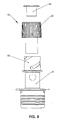
- FIG. 8 An example of a prior art tap 50 is shown in Fig. 8 and is marketed by Conro Precision in Cape Town, South Africa and disclosed for example in WO 01/02283 A1 .
- the tap 50 is applied to the bag with liquid, by inserting the body inside it through the above-described mouth and, upon using it by the end user, it is made go out of the cardboard box through an hole, opened by operating on a pre-dinked part for such purpose. Then the tap 50 itself is actuated, by rotating the plug 52 with which it is equipped around a cam end 56.
- Object of the present invention is solving the above prior art problems, by providing a delivering tap which is equipped with warranty seals that state its lack of unauthorised opening and is at the same time equipped with a head made of a single piece, reducing the number of pieces and the related end cost.
- Such tap moreover, being of a shorter thickness, removes problems of anomalous shrinkages of plastic materials, with a consequent better quality warranty of the moulded piece and the end product (complete tap), in addition to liquid tightness.
- a further object of the present invention is providing a tap of the above-mentioned type which is equipped, in at least two of its critical points, with sealing surfaces that allow a seal which is at least the same as the one available in nowadays known plugs.
- a further object of the present invention is providing a tap of the above-mentioned type, whose head is realised through an injection moulding process, which in this case is innovative and allows removing one piece from the end product, optimising manufacturing costs and times.
- Such moulding further allows improving the tap aesthetic appearance, since it almost completely reduces (making it unable to be perceived) the injection spot that in the prior art had to be covered by part 54.
- a further object of the present invention is providing a tap of the above-mentioned type which is equipped of a particular geometry of the plug sliding cam, which is improved with respect to the prior art.
- the delivering tap 1 of the invention substantially comprises:
- the characteristics of the delivering tap 1 are further that the plug 14 is made in a single piece; the plug 14 is equipped with tamper-preventing warranty sealing means 20 adapted to signal a possible tampering when opening the tap; and the body 3 is equipped with housing means 22 adapted to contain the tamper-preventing warranty sealing means 20.
- the tamper-preventing warranty sealing means 20 are composed of at least one ring 24 which surrounds the cylindrical end 15 and is connected to the knob 16 through a plurality of connecting members 26: such connecting members 26 are adapted to be detached from the knob 16 and/or the ring 24 upon firstly rotating the plug 14 when opening.
- the housing means 22 of the tamper-preventing warranty sealing means 20 are composed of at least one groove adapted to immovably house the ring 24.
- a tap can be thereby realised which is inexpensive, easy to assemble and which guarantees the end user with respect to authenticity of delivered liquid, demonstrating the lack of its tampering when there is the related seal.
- the tap 1 as described above weighs less than the prior art taps, given the lower use of material (plastics) of which it is composed and given the presence of a shorter moulding cycle.
- Fig. 7 shows a detail of the geometry of the cam 9 of the body 3 of the tap 1.
- Such cam 9 is lightened with respect to the one in known taps, which further optimises the amount of used material and therefore the related moulding cycles, which, by becoming quicker, also optimise the manufacturing costs.
- such geometry decreases the thicknesses (important aspect in this type of taps) decreasing the risk of anomalous post-moulding shrinkages, with consequent improvement of piece quality, above all in the area that can be found near the front area, which is the most important for the liquid seal.
- Lightening of the cam 9 is obtained by building the cam 9 itself through two walls 32, 34 projecting outwards from the surface of the end 7 of the body 3 and spirally wound around the end 7 itself.
- Such end 7 is thereby made with the same diameter of the corresponding parts of prior art taps 50 (for example see reference 56 in Fig. 8 ), but discharging, with respect to prior art taps 50, the cylindrical cam areas which were previously made thick.
- the thickness of the cam 9 allows avoiding anomalous shrinkages, while the two walls 32, 34 have been made grow by a necessary amount to allow the accurate and safe sliding of the small tooth, which will transform the rotary movement also in a translating movement, and allows opening the plug through an accurate sliding.
- the tap 1 provides, in addition to the mutual operating engagement of body 3 and cylindrical end 15 through their respective elongated cylindrical surfaces which guarantee an optimum seal every time, also the fact that the body 3 and the cylindrical end 15 of the plug 14 are in mutual contact in at least two sealing points (B, D in Fig. 9 ).
- the body 3 surface in contact with the cylindrical end 15 is plane and the cylindrical end 15 surface in contact with the body 3 is spherical. This guarantees a further seal in critical positions of the tap 1.
- the tap 1 also provides realising the related plug 14 in a single piece, reducing the number of component parts and improving the aesthetics (and above all reducing or removing some manufacturing steps) such as the injection spots that are present in prior art taps.
- the process which allows manufacturing such plug 14 in a single piece provides the use of an injection-moulding process whose use in this field is wholly new. Such process, first of all, provides, in order to make the body 3, common injection-moulding steps of the body 3 itself.
- the process further comprises, in order to mould the plug 14, the steps of:
- the tap 1 previously shown in a version with horizontal installation and use (namely, delivery) with respect to the box-shaped vessel to which it is applied, can also be realised in a version with horizontal installation but vertical use (namely, delivery), by only suitably configuring the outlet plug in a known way (and therefore not shown).
Landscapes
- Engineering & Computer Science (AREA)
- Mechanical Engineering (AREA)
- Closures For Containers (AREA)
- Moulds For Moulding Plastics Or The Like (AREA)
- Macromolecular Compounds Obtained By Forming Nitrogen-Containing Linkages In General (AREA)
- Devices For Dispensing Beverages (AREA)
- Bag Frames (AREA)
- Cigarettes, Filters, And Manufacturing Of Filters (AREA)
- Treatment Of Water By Ion Exchange (AREA)
- Extrusion Moulding Of Plastics Or The Like (AREA)
- Diaphragms For Electromechanical Transducers (AREA)
- Blow-Moulding Or Thermoforming Of Plastics Or The Like (AREA)
- Cartons (AREA)
- Packages (AREA)
- Containers And Packaging Bodies Having A Special Means To Remove Contents (AREA)
- Agricultural Chemicals And Associated Chemicals (AREA)
- Fats And Perfumes (AREA)
Claims (6)
- Versorgungshahn (1) für einen Flüssigkeitsbehälter der Art "bag in box" mit:- einem langen, grundlegend zylinderförmigen Körper (3), der mit einem Endstück (5) ausgestattet ist, das Ringe enthält, die für die Einhaltung der Dichte an einer Ausgusstülle dienen, mit der der Sack des Behälters ausgestattet ist, und mit einem entgegen gesetzten Endstück (7), das Nockenvorrichtungen (9) enthält, der genannte lange Körper (3) enthält außerdem ein ebenes Element (11), das auf einer senkrechten Fläche zur Achse des genannten Körpers (3) angebracht ist; und- einem Verschluss (14) mit einem zylinderförmigen Endstück (15) und einem Bedienungsknopf (16), der mit Spannvorrichtungen (18) der Nockenvorrichtungen (9) ausgestattet ist, der genannte Verschluss (14) dient dazu, operativ mit dem genannten Endstück (7) des genannten Körpers (3) verbunden zu werden, um auf den Befehl der genannten Nockenvorrichtungen (9) eine Öffnungsposition, in der die im Behälter enthaltene Flüssigkeit ausgegeben wird, sowie eine Schließposition im genannten Behälter einzunehmen, und der genannte Verschluss (14) ist aus einem Teil realisiert;und ist dadurch gekennzeichnet, dass:- der genannte Verschluss (14) mit beschädigungssicheren Garantiesiegeln (20) ausgestattet ist, die dazu dienen, eine eventuelle Beschädigung beim Öffnen des Hahns anzuzeigen; und- der genannte Körper (3) mit Aufnahmevorrichtungen (22) ausgestattet ist, die dazu dienen, die beschädigungssicheren Garantiesiegel (20) zu enthalten.
- Versorgungshahn (1) gemäß Patentanspruch 1, der dadurch gekennzeichnet ist, dass die genannten beschädigungssicheren Garantiesiegel (20) aus mindestens einem Ring (24) bestehen, der das genannte zylinderförmige Endstück (15) umschließt und mit dem genannten Knopf (16) durch mehrere Verbindungselemente (26) verbunden ist, die genannten Verbindungselemente (26) dienen dazu, durch den genannten Knopf (16) und/oder den genannten Ring (24) vor der Drehung des genannten Verschlusses (14) beim Öffnen getrennt zu werden.
- Versorgungshahn (1) gemäß Patentanspruch 2, der dadurch gekennzeichnet ist, dass die genannten Aufnahmevorrichtungen (22) der genannten beschädigungssicheren Garantiesiegel (20) aus mindestens einer Rille bestehen, die dazu dient, den genannten Ring (24) unbeweglich aufzunehmen.
- Versorgungshahn (1) gemäß Patentanspruch 1, der dadurch gekennzeichnet ist, dass der genannte Nocken (9) aus zwei Wänden (32, 34) besteht, die genannten Wände (32, 34) gehen aus der Oberfläche des genannten Endstücks (7) des genannten Körpers (3) hervor und umschließen das genannte Endstück (7) spiralförmig.
- Versorgungshahn (1) gemäß Patentanspruch 1, der dadurch gekennzeichnet ist, dass der genannte Körper (3) und das genannte zylinderförmige Endstück (15) des genannten Verschlusses (14) an mindestens zwei Dichtpunkten (B, D) gegenseitig in Kontakt stehen, an jedem dieser Dichtpunkte (B, D) ist die Oberfläche des genannten Körpers (3) mit dem genannten zylinderförmigen Endstück (15) in Kontakt, da sie eben ist, und die Oberfläche des genannten zylinderförmigen Endstücks (15) ist mit dem genannten Körper (3) in Kontakt, da sie sphärisch ist.
- Herstellungsverfahren eines Versorgungshahns (1) gemäß Patentanspruch 1, das dadurch gekennzeichnet ist, dass es folgende Phasen enthält:- Spritzgießen des genannten Körpers (3);- Zum Spritzgießen des genannten Verschlusses (14) Vorsehen einer Spritzform, die aus zwei Formhälften besteht, eine der genannten Formhälften ist fest, und in ihr ist eine Düse oder Angussbuchse eingesetzt, während die andere der genannten Formhälften beweglich ist, und in ihr ist eine Auswurfvorrichtung eingesetzt, der genannte Pressverschluss (14) ist an der Trennfläche zwischen den beiden genannten Formhälften angebracht;- Schließen der Spritzform;- Einspritzen des Materials zur Herstellung des genannten Verschlusses (14);- Öffnen der Form, zuerst am Trennbereich der genannten Formhälften;- Entfernen der genannten beweglichen Formhälfte;- Gleichzeitig mit der Entfernung der genannten beweglichen Formhälfte, Ziehen der Wagen nach außen, die durch geneigte Stifte mit der genannten beweglichen Formhälfte verbunden sind, die genannten Wagen dienen zur Realisierung der genannten Siegel (20), auf diese Weise werden die genannten Siegel (20) befreit;- Gleichzeitig mit dem Ziehen der Wagen, den vorderen Teil des genannten Verschlusses (14) befreien, da der Nut mit der genannten festen Formhälfte verbunden ist, in dem zwei Blockelemente eingesetzt sind, die genannten Blockelemente bilden einen Teil mit dem genannten Nut und bleiben an der genannten festen Seite der Form eingesetzt, die genannten Blockelemente haben die Funktion, während der Verbindung mit dem äußeren Stift, der sich an der genannten beweglichen Formhälfte befindet, die internen Zähne des genannten Knopfes (16) des genannten Verschlusses (14) zu bilden und das Endstück der Einspritzstelle herauszureißen;- Gleichzeitig mit Hilfe der genannten beweglichen Formhälfte und eines Verbindungselements zwischen den beiden Formhälften, den Zwischenstift, der sich am festen Teil der Form befindet, mit einer Platte der Form ziehen, sodass ein erster Vorschub des genannten Verschlusses (14) nach vom erfolgt;- Während die Öffnung der Form fortgesetzt wird, einen hydraulischen Abzieher betätigen, der mit dem hinteren Bereich der Form verbunden ist, um auf die Elemente der Form einzuwirken, die dazu dienen, den genannten Verschluss (14) vollständig von den Blöcken zu befreien, die an der genannten festen Formhälfte vorhanden sind; und- Beenden der Schließung der Form mit dem hydraulischen Abzieher, der, da er noch am hinteren Teil der Form mit einer Gewindestange verankert ist, die verschiedenen Platten und Tische in die entgegen gesetzte Richtung zieht und die Schließung ausführt.
Applications Claiming Priority (2)
| Application Number | Priority Date | Filing Date | Title |
|---|---|---|---|
| IT000612A ITTO20040612A1 (it) | 2004-09-13 | 2004-09-13 | Rubinetto erogatore e procedimento per la sua fabbricazione |
| PCT/IT2005/000465 WO2006030465A1 (en) | 2004-09-13 | 2005-08-02 | Delivering tap and process for manufacturing such tap |
Publications (2)
| Publication Number | Publication Date |
|---|---|
| EP1799608A1 EP1799608A1 (de) | 2007-06-27 |
| EP1799608B1 true EP1799608B1 (de) | 2008-06-25 |
Family
ID=34956611
Family Applications (1)
| Application Number | Title | Priority Date | Filing Date |
|---|---|---|---|
| EP05769496A Expired - Lifetime EP1799608B1 (de) | 2004-09-13 | 2005-08-02 | Ausgabehahn und verfahren zur herstellung eines solchen hahns |
Country Status (13)
| Country | Link |
|---|---|
| US (1) | US7681764B2 (de) |
| EP (1) | EP1799608B1 (de) |
| JP (1) | JP5112065B2 (de) |
| AT (1) | ATE399145T1 (de) |
| AU (1) | AU2005283732B2 (de) |
| CA (1) | CA2579009C (de) |
| DE (1) | DE602005007761D1 (de) |
| DK (1) | DK1799608T3 (de) |
| ES (1) | ES2308526T3 (de) |
| IT (1) | ITTO20040612A1 (de) |
| PT (1) | PT1799608E (de) |
| WO (1) | WO2006030465A1 (de) |
| ZA (1) | ZA200701342B (de) |
Families Citing this family (11)
| Publication number | Priority date | Publication date | Assignee | Title |
|---|---|---|---|---|
| US20080222272A1 (en) * | 2007-03-07 | 2008-09-11 | Optimal Licensing Corporation | System and method for substituting data in responses to multimedia inquiries |
| US8640931B2 (en) | 2011-02-01 | 2014-02-04 | Emerald Wine Systems, LLC | Tri-function tap for beverages |
| DE202013102908U1 (de) * | 2013-07-03 | 2013-07-16 | Sartorius Stedim Biotech Gmbh | Stabilisiertes Ventil mit Führung |
| EP2918543A3 (de) | 2014-03-14 | 2016-01-20 | Alenur Exportación, S.L. | Dosierungsspender-Verschlussanordnung für flüssige Verpackungsbehälter |
| EP3169621B1 (de) * | 2014-07-16 | 2021-09-08 | Coloplast A/S | Auslass für eine urostomievorrichtung |
| IT201700017332A1 (it) * | 2017-02-16 | 2017-05-16 | Vitop Moulding Srl | Rubinetto erogatore con apertura a camma |
| JP7016671B2 (ja) * | 2017-10-30 | 2022-02-07 | 日本クロージャー株式会社 | 注出具 |
| PT3849935T (pt) * | 2018-09-14 | 2025-01-13 | Vitop Moulding Srl | Torneira de distribuição com válvula interna com bordos flexíveis e múltiplos vedantes |
| IT202000022789A1 (it) | 2020-09-28 | 2020-12-28 | Vitop Moulding Srl | Rubinetto erogatore provvisto di sistema di collocamento, bloccaggio e orientamento su scatole di tipo Bag-In-Box |
| WO2022125498A1 (en) | 2020-12-07 | 2022-06-16 | Rieke Llc | Two piece, t-shaped dispensing tap and method of making same |
| JP7594489B2 (ja) * | 2021-04-27 | 2024-12-04 | Zacros株式会社 | 注出用スパウトおよび注出用スパウト付き容器 |
Family Cites Families (17)
| Publication number | Priority date | Publication date | Assignee | Title |
|---|---|---|---|---|
| US4351455A (en) * | 1980-06-19 | 1982-09-28 | Liqui-Box Corporation | Finger-actuated slideable dispensing valve |
| CA1206924A (en) | 1983-03-30 | 1986-07-02 | Paul F. Roos | Tap |
| US4478242A (en) * | 1983-08-25 | 1984-10-23 | Liqui-Box Corporation | Finger-actuated push-pull slideable dispensing valve |
| CA1239618A (en) * | 1984-04-04 | 1988-07-26 | Jiri Safarik | Liquid dispensing taps |
| BE1000760A6 (fr) * | 1987-07-27 | 1989-03-28 | Lynes Holding Sa | Dispositif de bouchon verseur. |
| FR2619612A1 (fr) | 1987-08-19 | 1989-02-24 | Dufrene Alain | Robinet de soutirage de liquides |
| US5111970A (en) * | 1991-03-12 | 1992-05-12 | Rapak, Inc. | Fluid dispenser having a removable sealing diaphragm |
| FR2732316B1 (fr) * | 1995-03-31 | 1997-05-30 | Rical Sa | Distributeur pour le soutirage d'un liquide d'un recipient |
| NL1006636C2 (nl) * | 1997-07-21 | 1999-01-25 | Itsac Nv | Verbindingssamenstel voor een fluïdumverbinding. |
| JP4076612B2 (ja) * | 1997-12-22 | 2008-04-16 | 大日本印刷株式会社 | 袋等に用いる蓋付き注出口 |
| DE19837947A1 (de) * | 1998-08-21 | 2000-02-24 | Kunststoffwerk & Formenbau Art | Entnahmevorrichtung für einen Flüssigkeitsbehälter |
| WO2001002283A1 (en) * | 1999-07-06 | 2001-01-11 | Paul Roos | Taps for liquid flow control |
| FR2828174B1 (fr) * | 2001-07-31 | 2003-09-26 | Rical Sa | Dispositif de bouchage d'un recipient et de soutirage d'un produit fluide |
| JP3794566B2 (ja) * | 2002-03-13 | 2006-07-05 | 株式会社アルエム | 注出口 |
| JP2004090980A (ja) * | 2002-08-30 | 2004-03-25 | Tenryu Kagaku Kogyo Kk | ピルファープルーフキャップ及びその製造方法並びに製造装置 |
| DE50204290D1 (de) * | 2002-12-23 | 2005-10-20 | Sisi Werke Gmbh | Verschlusselement mit trichterförmig zulaufendem Auslaufkanal |
| US7311229B1 (en) * | 2003-07-18 | 2007-12-25 | Illinois Tool Works Inc | Slide tap |
-
2004
- 2004-09-13 IT IT000612A patent/ITTO20040612A1/it unknown
-
2005
- 2005-08-02 AU AU2005283732A patent/AU2005283732B2/en not_active Expired
- 2005-08-02 WO PCT/IT2005/000465 patent/WO2006030465A1/en not_active Ceased
- 2005-08-02 JP JP2007530856A patent/JP5112065B2/ja not_active Expired - Lifetime
- 2005-08-02 DE DE602005007761T patent/DE602005007761D1/de not_active Expired - Lifetime
- 2005-08-02 EP EP05769496A patent/EP1799608B1/de not_active Expired - Lifetime
- 2005-08-02 DK DK05769496T patent/DK1799608T3/da active
- 2005-08-02 ES ES05769496T patent/ES2308526T3/es not_active Expired - Lifetime
- 2005-08-02 CA CA2579009A patent/CA2579009C/en not_active Expired - Lifetime
- 2005-08-02 US US10/556,173 patent/US7681764B2/en active Active
- 2005-08-02 PT PT05769496T patent/PT1799608E/pt unknown
- 2005-08-02 AT AT05769496T patent/ATE399145T1/de active
-
2007
- 2007-02-14 ZA ZA200701342A patent/ZA200701342B/en unknown
Also Published As
| Publication number | Publication date |
|---|---|
| ATE399145T1 (de) | 2008-07-15 |
| EP1799608A1 (de) | 2007-06-27 |
| CA2579009A1 (en) | 2006-03-23 |
| DK1799608T3 (da) | 2008-08-25 |
| AU2005283732B2 (en) | 2009-12-03 |
| ITTO20040612A1 (it) | 2004-12-13 |
| DE602005007761D1 (de) | 2008-08-07 |
| US7681764B2 (en) | 2010-03-23 |
| WO2006030465A1 (en) | 2006-03-23 |
| US20060261099A1 (en) | 2006-11-23 |
| JP5112065B2 (ja) | 2013-01-09 |
| AU2005283732A1 (en) | 2006-03-23 |
| CA2579009C (en) | 2013-11-05 |
| ES2308526T3 (es) | 2008-12-01 |
| ZA200701342B (en) | 2008-04-30 |
| PT1799608E (pt) | 2008-11-13 |
| JP2008512316A (ja) | 2008-04-24 |
Similar Documents
| Publication | Publication Date | Title |
|---|---|---|
| ZA200701342B (en) | Delivering tap and process for manufacturing such tap | |
| CN101878159B (zh) | 应用于液体封装的由塑料制成的可自动开合的浇铸件 | |
| US6116477A (en) | Two piece hinge closure | |
| EP0531394A1 (de) | Behälter zur ausgabe von tablette. | |
| EP3583065B1 (de) | Zapfhahn mit nocken-typ öffnungsmechanismus | |
| NZ210919A (en) | Two-piece dispensing closure for a container | |
| US11365112B2 (en) | Delivering tap with internal valve with flexible edges and multiple seals | |
| JP6051616B2 (ja) | 飲料用容器の栓体 | |
| EP3374314B1 (de) | Auslaufhahn aus kunststoff zum verbinden von systemen mit automatischem verschluss | |
| US4897032A (en) | Apparatus for making a closure device comprising a hinged cap for a container | |
| WO2006046262A1 (en) | Tap for dispensing liquids from vessels | |
| US20250289706A1 (en) | Dispensing tap for rigid and flexible containers, preferably of the bag-in-box type | |
| JPH10258854A (ja) | チューブ容器 | |
| FR2509262A1 (fr) | Fermeture a vis, de securite pour bouteilles, evitant le risque d'ouverture par les enfants | |
| WO2006055508A2 (en) | Source selecting cap and closure for multiple chamber bottles | |
| JP2000043912A (ja) | 不正開封防止機能付きキャップ及びその製造方法 | |
| JP2016222252A (ja) | 口栓 | |
| JPH0739812Y2 (ja) | 容器の注出装置 | |
| JP4404248B2 (ja) | 櫛付き容器 | |
| JP2005014998A (ja) | 二液混合分配容器 | |
| JPH0428528Y2 (de) | ||
| KR200311463Y1 (ko) | 병마개 | |
| KR200308976Y1 (ko) | 리필 기능을 갖는 밀폐용 캡 | |
| KR200238611Y1 (ko) | 주전자 수주구의 개폐장치 | |
| KR200317105Y1 (ko) | 장식공간이 형성된 용기 |
Legal Events
| Date | Code | Title | Description |
|---|---|---|---|
| PUAI | Public reference made under article 153(3) epc to a published international application that has entered the european phase |
Free format text: ORIGINAL CODE: 0009012 |
|
| 17P | Request for examination filed |
Effective date: 20070207 |
|
| AK | Designated contracting states |
Kind code of ref document: A1 Designated state(s): AT BE BG CH CY CZ DE DK EE ES FI FR GB GR HU IE IS IT LI LT LU LV MC NL PL PT RO SE SI SK TR |
|
| DAX | Request for extension of the european patent (deleted) | ||
| GRAP | Despatch of communication of intention to grant a patent |
Free format text: ORIGINAL CODE: EPIDOSNIGR1 |
|
| GRAS | Grant fee paid |
Free format text: ORIGINAL CODE: EPIDOSNIGR3 |
|
| GRAA | (expected) grant |
Free format text: ORIGINAL CODE: 0009210 |
|
| AK | Designated contracting states |
Kind code of ref document: B1 Designated state(s): AT BE BG CH CY CZ DE DK EE ES FI FR GB GR HU IE IS IT LI LT LU LV MC NL PL PT RO SE SI SK TR |
|
| REG | Reference to a national code |
Ref country code: GB Ref legal event code: FG4D |
|
| REG | Reference to a national code |
Ref country code: CH Ref legal event code: EP |
|
| REF | Corresponds to: |
Ref document number: 602005007761 Country of ref document: DE Date of ref document: 20080807 Kind code of ref document: P |
|
| REG | Reference to a national code |
Ref country code: IE Ref legal event code: FG4D |
|
| REG | Reference to a national code |
Ref country code: DK Ref legal event code: T3 |
|
| REG | Reference to a national code |
Ref country code: GR Ref legal event code: EP Ref document number: 20080402407 Country of ref document: GR |
|
| REG | Reference to a national code |
Ref country code: SE Ref legal event code: TRGR |
|
| PG25 | Lapsed in a contracting state [announced via postgrant information from national office to epo] |
Ref country code: SI Free format text: LAPSE BECAUSE OF FAILURE TO SUBMIT A TRANSLATION OF THE DESCRIPTION OR TO PAY THE FEE WITHIN THE PRESCRIBED TIME-LIMIT Effective date: 20080625 |
|
| REG | Reference to a national code |
Ref country code: PT Ref legal event code: SC4A Free format text: AVAILABILITY OF NATIONAL TRANSLATION Effective date: 20081027 |
|
| PG25 | Lapsed in a contracting state [announced via postgrant information from national office to epo] |
Ref country code: PL Free format text: LAPSE BECAUSE OF FAILURE TO SUBMIT A TRANSLATION OF THE DESCRIPTION OR TO PAY THE FEE WITHIN THE PRESCRIBED TIME-LIMIT Effective date: 20080625 Ref country code: LV Free format text: LAPSE BECAUSE OF FAILURE TO SUBMIT A TRANSLATION OF THE DESCRIPTION OR TO PAY THE FEE WITHIN THE PRESCRIBED TIME-LIMIT Effective date: 20080625 |
|
| REG | Reference to a national code |
Ref country code: ES Ref legal event code: FG2A Ref document number: 2308526 Country of ref document: ES Kind code of ref document: T3 |
|
| PG25 | Lapsed in a contracting state [announced via postgrant information from national office to epo] |
Ref country code: LT Free format text: LAPSE BECAUSE OF FAILURE TO SUBMIT A TRANSLATION OF THE DESCRIPTION OR TO PAY THE FEE WITHIN THE PRESCRIBED TIME-LIMIT Effective date: 20080625 Ref country code: IS Free format text: LAPSE BECAUSE OF FAILURE TO SUBMIT A TRANSLATION OF THE DESCRIPTION OR TO PAY THE FEE WITHIN THE PRESCRIBED TIME-LIMIT Effective date: 20081025 Ref country code: CZ Free format text: LAPSE BECAUSE OF FAILURE TO SUBMIT A TRANSLATION OF THE DESCRIPTION OR TO PAY THE FEE WITHIN THE PRESCRIBED TIME-LIMIT Effective date: 20080625 |
|
| PG25 | Lapsed in a contracting state [announced via postgrant information from national office to epo] |
Ref country code: SK Free format text: LAPSE BECAUSE OF FAILURE TO SUBMIT A TRANSLATION OF THE DESCRIPTION OR TO PAY THE FEE WITHIN THE PRESCRIBED TIME-LIMIT Effective date: 20080625 Ref country code: RO Free format text: LAPSE BECAUSE OF FAILURE TO SUBMIT A TRANSLATION OF THE DESCRIPTION OR TO PAY THE FEE WITHIN THE PRESCRIBED TIME-LIMIT Effective date: 20080625 |
|
| PG25 | Lapsed in a contracting state [announced via postgrant information from national office to epo] |
Ref country code: MC Free format text: LAPSE BECAUSE OF NON-PAYMENT OF DUE FEES Effective date: 20080831 |
|
| PG25 | Lapsed in a contracting state [announced via postgrant information from national office to epo] |
Ref country code: EE Free format text: LAPSE BECAUSE OF FAILURE TO SUBMIT A TRANSLATION OF THE DESCRIPTION OR TO PAY THE FEE WITHIN THE PRESCRIBED TIME-LIMIT Effective date: 20080625 Ref country code: BG Free format text: LAPSE BECAUSE OF FAILURE TO SUBMIT A TRANSLATION OF THE DESCRIPTION OR TO PAY THE FEE WITHIN THE PRESCRIBED TIME-LIMIT Effective date: 20080925 |
|
| PLBE | No opposition filed within time limit |
Free format text: ORIGINAL CODE: 0009261 |
|
| STAA | Information on the status of an ep patent application or granted ep patent |
Free format text: STATUS: NO OPPOSITION FILED WITHIN TIME LIMIT |
|
| REG | Reference to a national code |
Ref country code: IE Ref legal event code: MM4A |
|
| 26N | No opposition filed |
Effective date: 20090326 |
|
| PG25 | Lapsed in a contracting state [announced via postgrant information from national office to epo] |
Ref country code: IE Free format text: LAPSE BECAUSE OF NON-PAYMENT OF DUE FEES Effective date: 20080802 |
|
| REG | Reference to a national code |
Ref country code: CH Ref legal event code: PL |
|
| PG25 | Lapsed in a contracting state [announced via postgrant information from national office to epo] |
Ref country code: LI Free format text: LAPSE BECAUSE OF NON-PAYMENT OF DUE FEES Effective date: 20090831 Ref country code: CH Free format text: LAPSE BECAUSE OF NON-PAYMENT OF DUE FEES Effective date: 20090831 |
|
| PG25 | Lapsed in a contracting state [announced via postgrant information from national office to epo] |
Ref country code: LU Free format text: LAPSE BECAUSE OF NON-PAYMENT OF DUE FEES Effective date: 20080802 Ref country code: HU Free format text: LAPSE BECAUSE OF FAILURE TO SUBMIT A TRANSLATION OF THE DESCRIPTION OR TO PAY THE FEE WITHIN THE PRESCRIBED TIME-LIMIT Effective date: 20081226 Ref country code: CY Free format text: LAPSE BECAUSE OF FAILURE TO SUBMIT A TRANSLATION OF THE DESCRIPTION OR TO PAY THE FEE WITHIN THE PRESCRIBED TIME-LIMIT Effective date: 20080625 |
|
| PG25 | Lapsed in a contracting state [announced via postgrant information from national office to epo] |
Ref country code: IT Free format text: LAPSE BECAUSE OF NON-PAYMENT OF DUE FEES Effective date: 20100802 |
|
| PGRI | Patent reinstated in contracting state [announced from national office to epo] |
Ref country code: IT Effective date: 20110616 |
|
| PG25 | Lapsed in a contracting state [announced via postgrant information from national office to epo] |
Ref country code: IT Free format text: LAPSE BECAUSE OF NON-PAYMENT OF DUE FEES Effective date: 20150802 |
|
| REG | Reference to a national code |
Ref country code: FR Ref legal event code: PLFP Year of fee payment: 12 |
|
| REG | Reference to a national code |
Ref country code: FR Ref legal event code: PLFP Year of fee payment: 13 |
|
| REG | Reference to a national code |
Ref country code: FR Ref legal event code: PLFP Year of fee payment: 14 |
|
| PG25 | Lapsed in a contracting state [announced via postgrant information from national office to epo] |
Ref country code: IT Free format text: LAPSE BECAUSE OF NON-PAYMENT OF DUE FEES Effective date: 20150802 |
|
| PGRI | Patent reinstated in contracting state [announced from national office to epo] |
Ref country code: IT Effective date: 20190916 |
|
| PGFP | Annual fee paid to national office [announced via postgrant information from national office to epo] |
Ref country code: FR Payment date: 20240628 Year of fee payment: 20 |
|
| PGFP | Annual fee paid to national office [announced via postgrant information from national office to epo] |
Ref country code: NL Payment date: 20240826 Year of fee payment: 20 |
|
| PGFP | Annual fee paid to national office [announced via postgrant information from national office to epo] |
Ref country code: FI Payment date: 20240826 Year of fee payment: 20 Ref country code: DE Payment date: 20240822 Year of fee payment: 20 |
|
| PGFP | Annual fee paid to national office [announced via postgrant information from national office to epo] |
Ref country code: GR Payment date: 20240827 Year of fee payment: 20 Ref country code: DK Payment date: 20240826 Year of fee payment: 20 |
|
| PGFP | Annual fee paid to national office [announced via postgrant information from national office to epo] |
Ref country code: GB Payment date: 20240827 Year of fee payment: 20 Ref country code: PT Payment date: 20240820 Year of fee payment: 20 |
|
| PGFP | Annual fee paid to national office [announced via postgrant information from national office to epo] |
Ref country code: BE Payment date: 20240827 Year of fee payment: 20 |
|
| PGFP | Annual fee paid to national office [announced via postgrant information from national office to epo] |
Ref country code: ES Payment date: 20240902 Year of fee payment: 20 |
|
| PGFP | Annual fee paid to national office [announced via postgrant information from national office to epo] |
Ref country code: AT Payment date: 20240821 Year of fee payment: 20 |
|
| PGFP | Annual fee paid to national office [announced via postgrant information from national office to epo] |
Ref country code: IT Payment date: 20240703 Year of fee payment: 20 Ref country code: SE Payment date: 20240827 Year of fee payment: 20 |
|
| PGFP | Annual fee paid to national office [announced via postgrant information from national office to epo] |
Ref country code: TR Payment date: 20240823 Year of fee payment: 20 |
|
| REG | Reference to a national code |
Ref country code: DE Ref legal event code: R071 Ref document number: 602005007761 Country of ref document: DE |
|
| REG | Reference to a national code |
Ref country code: DK Ref legal event code: EUP Expiry date: 20250802 |
|
| REG | Reference to a national code |
Ref country code: NL Ref legal event code: MK Effective date: 20250801 |
|
| REG | Reference to a national code |
Ref country code: ES Ref legal event code: FD2A Effective date: 20250826 |
|
| REG | Reference to a national code |
Ref country code: GB Ref legal event code: PE20 Expiry date: 20250801 |
|
| REG | Reference to a national code |
Ref country code: AT Ref legal event code: MK07 Ref document number: 399145 Country of ref document: AT Kind code of ref document: T Effective date: 20250802 |
|
| REG | Reference to a national code |
Ref country code: SE Ref legal event code: EUG |
|
| PG25 | Lapsed in a contracting state [announced via postgrant information from national office to epo] |
Ref country code: ES Free format text: LAPSE BECAUSE OF EXPIRATION OF PROTECTION Effective date: 20250803 Ref country code: PT Free format text: LAPSE BECAUSE OF EXPIRATION OF PROTECTION Effective date: 20250812 |
|
| REG | Reference to a national code |
Ref country code: BE Ref legal event code: MK Effective date: 20250802 |