EP1800533B1 - Rateau pour une machine de fenaison - Google Patents
Rateau pour une machine de fenaison Download PDFInfo
- Publication number
- EP1800533B1 EP1800533B1 EP06026001A EP06026001A EP1800533B1 EP 1800533 B1 EP1800533 B1 EP 1800533B1 EP 06026001 A EP06026001 A EP 06026001A EP 06026001 A EP06026001 A EP 06026001A EP 1800533 B1 EP1800533 B1 EP 1800533B1
- Authority
- EP
- European Patent Office
- Prior art keywords
- tine
- free end
- group
- tines
- end portion
- Prior art date
- Legal status (The legal status is an assumption and is not a legal conclusion. Google has not performed a legal analysis and makes no representation as to the accuracy of the status listed.)
- Not-in-force
Links
- 238000004804 winding Methods 0.000 claims description 33
- 230000033001 locomotion Effects 0.000 claims description 11
- 239000000969 carrier Substances 0.000 abstract 1
- 235000000621 Bidens tripartita Nutrition 0.000 description 5
- 240000004082 Bidens tripartita Species 0.000 description 5
- HCHKCACWOHOZIP-UHFFFAOYSA-N Zinc Chemical compound [Zn] HCHKCACWOHOZIP-UHFFFAOYSA-N 0.000 description 5
- 208000006637 fused teeth Diseases 0.000 description 5
- 239000011701 zinc Substances 0.000 description 5
- 229910052725 zinc Inorganic materials 0.000 description 5
- 229910000639 Spring steel Inorganic materials 0.000 description 3
- 230000005540 biological transmission Effects 0.000 description 2
- 238000003780 insertion Methods 0.000 description 2
- 230000037431 insertion Effects 0.000 description 2
- 239000000463 material Substances 0.000 description 2
- 230000015572 biosynthetic process Effects 0.000 description 1
- 238000001514 detection method Methods 0.000 description 1
- 238000003306 harvesting Methods 0.000 description 1
- 238000009434 installation Methods 0.000 description 1
- OCDRLZFZBHZTKQ-NMUBGGKPSA-N onetine Chemical compound C[C@@H](O)[C@@]1(O)C[C@@H](C)[C@@](C)(O)C(=O)OC\C2=C\CN(C)CC[C@@H](OC1=O)C2=O OCDRLZFZBHZTKQ-NMUBGGKPSA-N 0.000 description 1
- 238000005457 optimization Methods 0.000 description 1
- 238000007493 shaping process Methods 0.000 description 1
- 238000010025 steaming Methods 0.000 description 1
- 239000010902 straw Substances 0.000 description 1
Images




Classifications
-
- A—HUMAN NECESSITIES
- A01—AGRICULTURE; FORESTRY; ANIMAL HUSBANDRY; HUNTING; TRAPPING; FISHING
- A01D—HARVESTING; MOWING
- A01D80/00—Parts or details of, or accessories for, haymakers
- A01D80/02—Tines; Attachment of tines
Definitions
- the invention relates to a rake for a haymaking machine according to the preamble of claim 1, and a double tines, which is designed for use on such a rake in a haymaking machine, often called rake.
- the tines are each designed as double tines. From one attached to a tine carrier tangent protrudes tangentially from each of its two ends, one of which is generally rectilinear and the other is cranked so that its effective for the detection of stalks free end portion at a certain distance from the first, straight tines and parallel to this lies.
- the tine leans with the offset to the associated rectilinear prongs, both of which rotate about the longitudinal axis of the winding.
- the purpose of this arrangement is that the trailing tine should grasp additional crop to be left by the other leading tine, thus improving the working quality of the machine over a single tine row solution on each rake of a work station.
- the rake each have only a single row of tines.
- the end portions of the tines are angled relative to their perpendicular projecting from the tine carrier initial sections in the longitudinal direction of the tine carrier to the inner end.
- the end sections as well as the initial sections each exactly parallel to each other.
- the end portions of the pair of tines on the tine carrier outermost tine pair are angled towards the outer end of the tine carrier and at the same time in the circumferential direction with respect to the longitudinal axis of the tine carrier forward.
- this embodiment is not intended for steaming, but only for the turning or tedding operation of the machine and is intended to reinforce the backward centrifugal effect of the rake.
- the rakes When changing between the different operating modes, the rakes must be replaced.
- a machine for processing of crops lying on the ground in which no rake with a row arrangement of prongs, but only individual pairs of tines are used as processing tools for receiving and redistributing crop, the legs of a spread apart orientation to each other in the longitudinal direction of the Have tine carrier and stand both in the working position significantly oblique to the ground.
- the peculiarity of this machine is that the position of the tine pairs can be adjusted manually and locked in different positions in order to adapt to different operations of the machine and / or to different types of crop to be processed.
- the object of the invention is to provide a new rake for a haymaking machine, with which the working quality of the machine can be further increased, and to provide a double tine for use on such a rake.
- the inventive skewing of at least the free end portions of the tines of at least one of the two tine groups of a rake relative to those of the other tine group is achieved that the tine group can detect with the oblique end portions of the tines and those blades that are at a steep angle to the ground, i. whose position does not deviate far from a vertical position.
- Such straws are not effectively detected by a rake whose tines with their free end portion at the lowest point of their rotational motion are approximately perpendicular to the ground.
- a clue for the dimensioning of the inclination of the free end portions of a tine group forms the offset between the two tine groups in the direction of the longitudinal axis of the tine carrier.
- the angle at which the free end portions of the tines of one group are inclined to those of the other group is selected so that said offset between the two tine groups is at least approximately bridged by the inclined position. This ensures that even at a steep angle to the ground stalks can be effectively detected by the tines of the group with oblique end portions.
- Double tines for a rake according to the invention in each of which one tine of one group is combined in one piece with a tine of the other group.
- Double tines of a single type arranged side by side in a row, which simplifies the preparation of the tines and the installation of the rake and any repair work.
- FIG. 1 and 2 is a haymaking machine, also called rake, shown with a working top 1 in a side view.
- the machine is pulled by a tractor 2 and driven.
- the working top 1 In the working position shown, the working top 1 by a machine frame 3, which runs on wheels 4, horizontally at a suitable distance from Ground led.
- the working top 1 rotates counterclockwise in the operation of the machine, as in Fig. 2 is indicated by a curved arrow. It contains a plurality of rakes 5, each consisting of a tine carrier 6A, 6B and a plurality of tines 7.
- the tines 7 of a rake 5 are in this case rotatably mounted on an outer portion 6B of the tine carrier 6A, 6B, whose inner portion 6A is rotatably mounted in a mounted on a gear 8 bell 8A about its longitudinal axis.
- Fig. 2 is still on one of the rake 5, the longitudinal axis 6C of the outer portion 6B of the tine carrier 6A, 6B located, which is for later explanations of importance.
- each rake 5 are in the course of one revolution of the working top 1 by a rotational movement of the respective tine carrier 6A, 6B effected by the transmission 8 between an approximately horizontally raised position, which is raised from the ground Fig. 1 on the left, and a lowered, almost vertical, position lowered to the ground Fig. 1 on the right is moved back and forth so that they arrive depending on their current position on the circumference of the working top 1 alternately out of or in engagement with the crop to be collected.
- a swath towel 10 suspended on a boom 9 limits the width of the swath 11 formed.
- the tines 7 of a rake 5 are preferably made of spring steel. As in Fig. 1 best right and in Fig. 2 can best be seen on the left, the tines 7 are each arranged in rows along the outer portion 6B of the tine carrier 6A, 6B.
- a rake 5 has two groups 7A and 7B of tines 7, namely those 7A which protrude approximately in a straight line perpendicularly from the outer portion 6B of the tine carrier 6A, 6B, and those 7B which are angled in a certain direction, therefore at least partially, namely to their free end, diagonally to the other 7A run.
- Both tine groups 7A and 7B are each arranged as an equidistant row and the two rows are offset from one another in the direction of the longitudinal axis of the outer portion 6B of the tine carrier 6A, 6B.
- the shape of the tines 7 of each of the two groups 7A and 7B and their arrangement relative to each other will be explained in detail below with reference to a single tine pair comprising two immediately adjacent tines, each of which belongs to a different one of the two tine groups 7A and 7B.
- the pair of tines expediently has the form of a so-called double tine, ie the two tines of the pair are made of a single piece of spring steel, that is, integrally connected to one another.
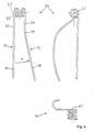
- Fig. 3 shows three different views of a first embodiment of a double tine 20 according to the invention.
- the top right view is the side view in the lowered position to the ground, the viewing direction of the direction of the longitudinal axis 6C of the outer portion 6B of the tine carrier 6A, 6B corresponds, namely radially outwardly in relation on the work top 1.
- the double teeth 20 is folded from the side view in a known manner about a vertical axis to the left or about a horizontal axis upwards.
- the in Fig. 3 shown double prong 20 consists of a first prong 21, a second prong 22 and a winding 23, which connects the two prongs 21 and 22 together and is prepared by the shape of a central portion 24 thereto, rotatably attached to the outer portion 6B of the tine carrier 6A, 6B to be so, that the longitudinal axis of the winding 23 coincides with the longitudinal axis 6C of the outer portion 6B of the tine carrier 6A, 6B.
- the longitudinal axis of the winding 23 is therefore in Fig. 3 also marked with 6C.
- the tines 21 and 22 and the winding 23 are made of a single piece of spring steel of preferably circular cross-section.
- the first tine 22 is leading with respect to the direction of movement B to the ground and the second tine 22 lagging. Due to its straight tangential Abragens from the winding 23, the first tine 21 in the top right down right actually not seen and therefore there identified by a black circle at the lower right end of the winding 23.
- the first prong 21 has an initial portion 25 extending from one end of the winding 23 and a free end portion 26 intended for engagement with the crop to be collected.
- the second prong 22 has an initial section 27 extending from the other end of the winding 23, and a free end section 28 intended for engagement with the crop to be collected. It stands out Beginning portion 27 of the second tine 22 as well as the initial portion 25 of the first tine 21 tangentially, but obliquely to this and, with respect to the intended direction of movement B against the ground, backwards from the winding 23 from, which in the side view of Fig. 3 is readily apparent.
- the second prong 22 still has a curvature section 29, in which the direction of the prong 22 changes relative to the start section 27, in such a way that inter alia in the side view, the angle between its end section 28 and 26 of the first tine 21 is smaller than the angle between the two start portions 27 and 25.
- the curvature in this view only serves to set an appropriate distance between the two end portions 26 and 28 and is not critical to the present invention.
- the change of direction of the second prong 22 in the curved section 29 ensures that the ends of the two prongs 21 and 22 are approximately in line with each other with respect to the direction of movement B.
- the angle ⁇ of the inclination of the free end portion 28 of the second tine 22 in the front view is thus selected so that the distance of the end of the free end portion 28 of the second tine 22 from its initial portion 27 in the direction of the longitudinal axis 6C of the winding 23 is about the distance of two initial sections 25 and 27 of the two prongs 21 and 22 corresponds.
- the angle ⁇ is approximately 15 ° in the example shown.
- the amount of the angle can vary within wide limits, wherein for achieving a certain distance of the end of the free end portion 28 of the initial portion 27 in the direction of the longitudinal axis 6C of Winding 23 of the angle ⁇ must be selected to be greater, the longer the tangential to the winding 23, rectilinear beginning portion 27 is.
- the optimization of the various geometric parameters of the curved second tine 22 is within the skill of the art.
- a guide for this is the distance of the beginning portions 25 and 27 of the two prongs 21 and 22 in the front view, which should be bridged by the inclination of the free end portion 28 of the second prong 22 in the front view, preferably at least approximately, as in Fig. 3 you can see. It may also be useful in principle that the free end portion 28 of the second tine 22 in the front view crosses the free end portion 26 of the first tine 21, so that its end in the illustration of Fig. 3
- the overall length of the two prongs 21 and 22 is a matter of adapting the position of their ends to the axis of rotation 6C acting as an axis of rotation in operation.
- the effect intended by the present invention of detecting steep stalks does not depend on the second prong 22, which in operation within a haymaking machine lags the first prong 21 with respect to contact with the stalk material, in front view having oblique end portion 28.
- the end section 28 of the second tine 22 could instead be straight and instead the end section 26 of the first tine 21 should be angled obliquely. The inclination of an end portion 26 or 28 is thus interchangeable between the two prongs 21 and 22.
- FIGS. 4 to 8 Further embodiments of a double teeth according to the invention are shown, which fulfill the same basic function as the first embodiment and these are largely similar in shape. The following description of these further embodiments is therefore limited essentially to the presentation of the particular features of the first Embodiment after Fig. 3 differ. For the Dimensontechnik of the geometric parameters of the second zinc apply in all other embodiments mutatis mutandis, the same aspects as in the first embodiment.
- FIG. 2 shows a second embodiment of a double tooth 30 according to the invention, which differs from the first one only in that, in the upper left view, the curvature of the second tine 32 in the curvature section 39 has a direction opposite to the first embodiment, so that the free end section 38 of the second tine 32 is not directed toward the free end portion 36 of the first tine 31 but away from it. Also in this embodiment, 32 blades, which are nearly perpendicular to the ground, can be detected by the inclined free end portion 38 of the second tine 32.
- the angle ⁇ of the inclination of the free end portion 38 of the second prong 32 in the front view exactly the same as in the first embodiment, but has the opposite direction, and the distance between the ends of the free end portions 36 and 38 of the two prongs 31 and 32 is approximately twice the distance of the starting portions 35 and 37.
- the distance of the end of the free end portion 38 of the initial portion 37 in the direction of the longitudinal axis 6C of the winding 33 is about the distance of the two initial sections 35th and 37 of the two prongs 31 and 32.
- Fig. 5 shows a third embodiment of a double-tine 40 according to the invention, which differs from the first in that the curvature of the second prong 42 is not limited to only a relatively short area in the top right side view, but the curved portion 49 is elongated and flowing in the Furthermore, the total curvature angle is so large that the free end portion 48 in side view is no longer away from the free end portion 46 of the first straight tine 41, but toward him.
- the shape of the double tine 40 with respect to the invention essential skew the free End portion 48 of the second tine 42 in this view with the first embodiment.
- the fourth in Fig. 6 shown embodiment of a double zinc 50 is the third in the same relationship as the second to the first. That is, it differs from the third embodiment only in that, in the upper left-hand upper view, the curvature of the second tine 52 in the curvature portion 59 has an opposite direction, so that the free end portion 58 of the second tine 52 does not face in the front view the free end portion 56 of the first prong 51 to, but is directed away from it. Also in this embodiment can be detected by the sloping free end portion 58 of the second tine 52 blades, which are nearly perpendicular to the ground.
- the angle of inclination of the free end portion 58 of the second prong 52 in the front view is exactly the same as in the third embodiment, but has the opposite direction, and the distance between the ends of the free end portions 56 and 58th
- the distance of the end of the free end portion 58 from the initial portion 57 in the direction of the longitudinal axis 6C of the winding 53 about the distance between the two start portions 55 and 57 of the two prongs 51 and 52.
- Fig. 7 shows a fifth embodiment of a double zinc 60 according to the invention, which differs from the first in Fig. 3 is distinguished in particular by the fact that in the upper right side view the curvature angle of the second tine 62 realized by the curvature section 69 is so great that the free end section 68 of the second tine 62 is no longer away from the free end section 66 of the first straight tine 61. but is directed towards him.
- This inclination of the free end portion 68 of the second prong 62 in the direction of movement B may be advantageous for engagement with the crop to be collected.
- the shape of the double zinc 60 with respect to the invention essential inclination of the free end portion 68 of the second prong 62 in this view with the first Embodiment basically match.
- the starting portion 67 of the second tine 62 protruding in a straight line from the winding 63 is longer and the free end portion 68 for it is shorter.
- the angle ⁇ between the end portion 68 of the second prong 62 and End portion 66 of the first prong 61 correspondingly larger than in the first embodiment.
- FIG Fig. 8 A sixth embodiment of a double tine 70 according to the invention is shown in FIG Fig. 8 shown.
- This embodiment differs from the fifth only in that in the upper left upper view, the curvature of the second tine 72 in the curved portion 79 has an opposite direction, so that the free end portion 78 of the second tine 72 does not touch the free end portion 76 of the first tine 71 too, but is directed away from it. Also in this embodiment, stalks that are nearly perpendicular to the ground can be detected by the sloping free end portion 78 of the second tine 72.
- the angle ⁇ of the inclination of the free end portion 78 of the second prong 72 in the front view is exactly the same as in the fifth embodiment, but has the opposite direction, and the distance between the ends of the free end portions 76 and
- the distance of the end of the free end portion 78 from the initial portion 77 in the direction of the longitudinal axis 6C of the winding 73 about the distance of the two initial portions 75 corresponds to 78 of the two prongs 71 and 72 is approximately twice the distance of the initial sections and 77 of the two prongs 71 and 22.
- the individual rakes 5 of a work top 1 can be arranged offset in the radial direction against each other, which, for example, by a variation of the length of the tine carrier 6A, 6B, or can be achieved by a variation of the insertion depth of the inner portion 6A in the transmission 8. It could for this purpose but also with the same length and insertion depth of the tine carrier 6A, 6B, the position of the tines 7 on the outer portions 6B between the various rakes 5 are varied by a respective offset in the direction of the axis 6C. Another possibility would be to mount on different rakes 5 different tines 7 with different angles ⁇ of the second tine group 7B.
- a rake according to the invention could also be realized by mounting two different types of separate individual tines alternately in a row along the outer portion 6B of a tine carrier 6A, 6B.
- the formation of the two different types of tines 7 of a rake 5 according to the invention in the form of one-piece double tines of the type described above is particularly advantageous, so also represents the alternative implementation with different types of single tines a possible embodiment of the present invention.
Landscapes
- Life Sciences & Earth Sciences (AREA)
- Environmental Sciences (AREA)
- Soil Working Implements (AREA)
- Outside Dividers And Delivering Mechanisms For Harvesters (AREA)
- Saccharide Compounds (AREA)
- Preliminary Treatment Of Fibers (AREA)
- Electrical Discharge Machining, Electrochemical Machining, And Combined Machining (AREA)
Claims (22)
- Râteau pour une machine de fenaison, avec une pluralité de dents flexibles fixées sur un porte-dents, sachant que deux groupes de dents sont disposés en juxtaposition, chacun en une rangée, le long d'une partie extérieure du porte-dents, et sont ce faisant mutuellement décalés dans la direction de l'axe longitudinal de la partie extérieure du porte-dents de telle sorte que, parmi deux dents immédiatement voisines, chacune d'entre elles fait chaque fois partie de l'un des deux groupes de dents différents, et sachant que les dents du deuxième groupe possèdent une forme et une orientation telles qu'au moins leurs parties terminales libres présentent, par rapport aux parties terminales libres des dents du premier groupe, une distance dans la direction circonférentielle d'un cercle s'étendant autour de l'axe longitudinal de la partie extérieure du porte-dents, caractérisé en ce que, pour au moins un des deux groupes de dents (7A, 7B), au moins les parties terminales libres (28 ; 38 ; 48 ; 58 ; 68 ; 78) des dents (22 ; 32 ; 42 ; 52 ; 62 ; 72) sont orientées de telle sorte que, dans un premier plan situé entre les deux groupes de dents (7A, 7B) et parallèlement à l'axe longitudinal (6C) de la partie extérieure (6B) du porte-dents (6A, 6B), leurs projections s'étendent en oblique par rapport aux projections des parties terminales libres (26 ; 36 ; 46 ; 56 ; 66 ; 76) de l'autre groupe de dents respectif (7A).
- Râteau selon la revendication 1, caractérisé en ce que les dents du premier groupe de dents (7A) possèdent une forme et une orientation telles qu'au moins leurs parties terminales libres (26 ; 36 ; 46 ; 56 ; 66 ; 76) s'étendent environ parallèlement entre elles et environ perpendiculairement à un axe longitudinal (6C) de la partie extérieure (6B) du porte-dents, et en ce que, pour le deuxième groupe de dents (7B), au moins les parties terminales libres (28 ; 38 ; 48 ; 58 ; 68 ; 78) des dents (22 ; 32 ; 42 ; 52 ; 62 ; 72) sont orientées de telle sorte que, dans le premier plan, leurs projections s'étendent en oblique par rapport aux projections des parties terminales libres (26 ; 36 ; 46 ; 56 ; 66 ; 76) du premier groupe de dents (7A).
- Râteau selon la revendication 1 ou 2, caractérisé en ce que les dents (22 ; 32 ; 42 ; 52 ; 62 ; 72) du deuxième groupe (7B) sont, par rapport à celles (21 ; 31 ; 41 ; 51 ; 61 ; 71) du premier groupe (7A), dans leurs parties initiales respectives (25, 27 ; 35, 37 ; 45, 47 ; 55, 57 ; 65, 67 ; 75, 77) qui partent de la partie extérieure (6B) du porte-dents (6A, 6B), décalées dans la direction de l'axe longitudinal (6C) de la partie extérieure (6B) du porte-dents (6A, 6B) et en ce que, dans le premier plan, l'angle α entre les projections des parties terminales libres (28 ; 38 ; 48 ; 58 ; 68 ; 78) du deuxième groupe de dents (7B) et de celles (26 ; 36 ; 46 ; 56 ; 66 ; 76) du premier groupe de dents (7A) est d'une grandeur telle que l'étendue des parties terminales (28 ; 38 ; 48 ; 58 ; 68 ; 78), s'étendant en oblique, des dents (22 ; 32 ; 42 ; 52 ; 62 ; 72) d'au moins un des deux groupes de dents (7A, 7B) dans la direction de l'axe longitudinal (6C) de la partie extérieure (6B) du porte-dents (6A, 6B) est au moins approximativement égale ou supérieure à la distance entre une partie initiale (25 ; 35 ; 45 ; 55 ; 65 ; 75) d'une dent (21 ; 31 ; 41 ; 51 ; 61 ; 71) du premier groupe (7A) et la partie initiale (27 ; 37 ; 47 ; 57 ; 67 ; 77) de la dent la plus proche (22 ; 32 ; 42 ; 52 ; 62 ; 72) du deuxième groupe (7B).
- Râteau selon l'une des revendications 1 à 3, caractérisé en ce que, dans le premier plan, l'angle α entre les projections des parties terminales libres (28 ; 38 ; 48 ; 58 ; 68 ; 78) du deuxième groupe de dents (7B) et de celles (26 ; 36 ; 46 ; 56 ; 66 ; 76) du premier groupe de dents (7A) est au moins égal à 10°.
- Râteau selon l'une des revendications 1 à 4, caractérisé en ce que, dans le premier plan, l'angle α entre les projections des parties terminales libres (28 ; 38 ; 48 ; 58 ; 68 ; 78) du deuxième groupe de dents (7B) et de celles (26 ; 36 ; 46 ; 56 ; 66 ; 76) du premier groupe de dents (7A) est au plus égal à 80°.
- Râteau selon l'une des revendications 1 à 5, caractérisé en ce que les dents (22 ; 32 ; 42 ; 52 ; 62 ; 72) du deuxième groupe de dents (7B) présentent chacune une partie incurvée (29 ; 39 ; 49 ; 59 ; 69 ; 79) située entre une partie initiale (27 ; 37 ; 47 ; 57 ; 67 ; 77) et la partie terminale libre (28 ; 38 ; 48 ; 58 ; 68 ; 78), et en ce qu'on produit par l'incurvation de la partie incurvée (29 ; 39 ; 49 ; 59 ; 69 ; 79) l'allure oblique des projections de leurs parties terminales libres (28 ; 38 ; 48 ; 58 ; 68 ; 78) par rapport aux projections des parties terminales libres (26 ; 36 ; 46 ; 56 ; 66 ; 76) du premier groupe de dents (7A) dans le premier plan.
- Râteau selon la revendication 6, caractérisé en ce que les projections des parties initiales (25, 27 ; 35, 37 ; 45, 47 ; 55, 57 ; 65, 67 ; 75, 77) des dents des deux groupes de dents (7A, 7B) dans le premier plan s'étendent environ parallèlement entre elles.
- Râteau selon la revendication 6 ou 7, caractérisé en ce que, dans un deuxième plan situé perpendiculairement à l'axe longitudinal de la partie extérieure (6B) du porte-dents (6A, 6B), les projections des parties initiales (27 ; 37 ; 47 ; 57 ; 67 ; 77) du deuxième groupe de dents (7B) s'étendent en oblique par rapport aux projections des parties initiales (25 ; 35 ; 45 ; 55 ; 65 ; 75) du premier groupe de dents (7A), et en ce que les dents (22 ; 32 ; 42 ; 52 ; 62 ; 72) du deuxième groupe (7B) sont, dans la partie incurvée (29 ; 39 ; 49 ; 59 ; 69 ; 79), incurvées de telle sorte que, dans le deuxième plan, l'angle entre les projections de leurs parties terminales (28 ; 38 ; 48 ; 58 ; 68 ; 78) et les projections des parties terminales (26 ; 36 ; 46 ; 56 ; 66 ; 76) du premier groupe de dents (7A) est inférieur à l'angle entre les projections des parties initiales (25, 27 ; 35, 37 ; 45, 47 ; 55, 57 ; 65, 67 ; 75, 77) des deux groupes de dents (7A, 7B), ou possède une direction opposée par rapport à cet angle.
- Râteau selon l'une des revendications 6 à 8, caractérisé en ce que la partie initiale (27 ; 37 ; 47 ; 57 ; 67 ; 77) et la partie terminale (28 ; 38 ; 48 ; 58 ; 68 ; 78) d'une dent (22 ; 32 ; 42 ; 52 ; 62 ; 72) du deuxième groupe (7B) s'étendent respectivement approximativement de façon rectiligne.
- Râteau selon l'une des revendications 6 à 8, caractérisé en ce que la partie incurvée (29 ; 39 ; 49 ; 59 ; 69 ; 79) d'une dent (22 ; 32 ; 42 ; 52 ; 62 ; 72) du deuxième groupe (7B) se raccorde par une transition insensible à sa partie terminale (28 ; 38 ; 48 ; 58 ; 68 ; 78), de sorte que cette dernière s'étend également de manière incurvée.
- Râteau selon l'une des revendications 1 à 10, caractérisé en ce que le premier groupe de dents (7A) se trouve en position antérieure par rapport au deuxième groupe de dents (7B) relativement à la direction de déplacement du râteau (5) lors de son utilisation dans une machine de fenaison.
- Râteau selon l'une des revendications 1 à 11, caractérisé en ce qu'une dent (21 ; 31 ; 41 ; 51 ; 61 ; 71) du premier groupe (7A) et une dent (22 ; 32 ; 42 ; 52 ; 62 ; 72) du deuxième groupe (7B) sont chaque fois réalisées sous forme de dent double (20 ; 30 ; 40 ; 50 ; 60 ; 70) d'un seul tenant et se raccordent l'une à l'autre en un enroulement (23 ; 33 ; 43 ; 53 ; 63 ; 73), au niveau duquel la dent double (20 ; 30 ; 40 ; 50 ; 60 ; 70) peut être reliée à la partie extérieure (6B) du porte-dents (6A, 6B).
- Dent double pour un râteau d'une machine de fenaison, avec un enroulement pouvant être fixé à un porte-dents et deux dents flexibles partant en saillie des deux extrémités de l'enroulement, sachant que la deuxième dent possède une forme et une orientation telles qu'au moins sa partie terminale libre présente, par rapport à la partie terminale libre de la première dent, une distance dans la direction circonférentielle d'un cercle s'étendant autour de l'axe longitudinal de l'enroulement, et sachant qu'au moins la partie terminale libre (28 ; 38 ; 48 ; 58 ; 68 ; 78) d'une des deux dents (21, 22 ; 31, 32 ; 41, 42 ; 51, 52 ; 61, 62 ; 71, 72) est orientée de telle sorte que, dans un premier plan situé entre les deux dents (21, 22 ; 31, 32 ; 41, 42 ; 51, 52 ; 61, 62 ; 71, 72) et parallèlement à l'axe longitudinal (6C) de l'enroulement (23 ; 33 ; 43 ; 53 ; 63 ; 73), sa projection s'étend en oblique par rapport à la projection de la partie terminale libre (26 ; 36 ; 46 ; 56 ; 66 ; 76) de l'autre dent (21 ; 31 ; 41 ; 51 ; 61 ; 71), caractérisée en ce que, dans le premier plan, l'angle entre les projections de la partie terminale libre (28 ; 38 ; 48 ; 58 ; 68 ; 78) de la deuxième dent (22 ; 32 ; 42 ; 52 ; 62 ; 72) et de celle (26 ; 36 ; 46 ; 56 ; 66 ; 76) de la première dent (21 ; 31 ; 41 ; 51 ; 61 ; 71) est d'une grandeur telle que l'étendue de la partie terminale (28 ; 38 ; 48 ; 58 ; 68 ; 78), s'étendant en oblique, d'une des deux dents (21, 22 ; 31, 32 ; 41, 42 ; 51, 52 ; 61, 62 ; 71, 72) dans la direction de l'axe longitudinal (6C) de l'enroulement (23 ; 33 ; 43 ; 53 ; 63 ; 73) est au moins approximativement égale ou supérieure à la longueur de l'enroulement (23 ; 33 ; 43 ; 53 ; 63 ; 73).
- Dent double selon la revendication 13, caractérisée en ce que la première des deux dents possède une forme et une orientation telles qu'au moins sa partie terminale libre s'étend environ perpendiculairement à l'axe longitudinal de l'enroulement (23 ; 33 ; 43 ; 53 ; 63 ; 73), et en ce que la partie terminale libre (28 ; 38 ; 48 ; 58 ; 68 ; 78) de la deuxième dent (22 ; 32 ; 42 ; 52 ; 62 ; 72) est orientée de telle sorte que, dans un premier plan situé entre les deux dents (21, 22 ; 31, 32 ; 41, 42 ; 51, 52 ; 61, 62 ; 71, 72) et parallèlement à l'axe longitudinal (6C) de l'enroulement (23 ; 33 ; 43 ; 53 ; 63 ; 73), sa projection s'étend en oblique par rapport à la projection de la partie terminale libre (26 ; 36 ; 46 ; 56 ; 66 ; 76) de la première dent (21 ; 31 ; 41 ; 51 ; 61 ; 71).
- Dent double selon la revendication 13 ou 14, caractérisée en ce que, dans le premier plan, l'angle α entre les projections de la partie terminale libre (28 ; 38 ; 48 ; 58 ; 68 ; 78) de la deuxième dent (22 ; 32 ; 42 ; 52 ; 62 ; 72) et de celle (26 ; 36 ; 46 ; 56 ; 66 ; 76) de la première dent (21 ; 31 ; 41 ; 51 ; 61 ; 71) est au moins égal à 10°.
- Dent double selon l'une des revendications 13 à 15, caractérisée en ce que, dans le premier plan, l'angle α entre les projections de la partie terminale libre (28 ; 38 ; 48 ; 58 ; 68 ; 78) de la deuxième dent (22 ; 32 ; 42 ; 52 ; 62 ; 72) et de celle (26 ; 36 ; 46 ; 56 ; 66 ; 76) de la première dent (21 ; 31 ; 41 ; 51 ; 61 ; 71) est au plus égal à 80°.
- Dent double selon l'une des revendications 13 à 16, caractérisée en ce que la deuxième dent (22 ; 32 ; 42 ; 52 ; 62 ; 72) présente une partie initiale (27 ; 37 ; 47 ; 57 ; 67 ; 77) voisine de l'enroulement (23 ; 33 ; 43 ; 53 ; 63 ; 73) et une partie incurvée (29 ; 39 ; 49 ; 59 ; 69 ; 79) située entre cette partie initiale et la partie terminale libre (28 ; 38 ; 48 ; 58 ; 68 ; 78), et en ce qu'on produit par l'incurvation de la partie incurvée (29 ; 39 ; 49 ; 59 ; 69 ; 79) l'allure oblique de la projection de sa partie terminale libre (28 ; 38 ; 48 ; 58 ; 68 ; 78) par rapport à la projection de la partie terminale libre (26 ; 36 ; 46 ; 56 ; 66 ; 76) de la première dent (21 ; 31 ; 41 ; 51 ; 61 ; 71) dans le premier plan.
- Dent double selon la revendication 17, caractérisée en ce que les projections des parties initiales (25, 27 ; 35, 37 ; 45, 47 ; 55, 57 ; 65, 67 ; 75, 77) des deux dents (21, 22 ; 31, 32 ; 41, 42 ; 51, 52 ; 61, 62 ; 71, 72) dans le premier plan s'étendent environ parallèlement entre elles.
- Dent double selon la revendication 17 ou 18, caractérisée en ce que, dans un deuxième plan situé perpendiculairement à l'axe longitudinal (6C) de l'enroulement (23 ; 33 ; 43 ; 53 ; 63 ; 73), la projection de la partie initiale (27 ; 37 ; 47 ; 57 ; 67 ; 77) de la deuxième dent (22 ; 32 ; 42 ; 52 ; 62 ; 72) s'étend en oblique par rapport à la projection de la partie initiale (25 ; 35 ; 45 ; 55 ; 65 ; 75) de la première dent (21 ; 31 ; 41 ; 51 ; 61 ; 71), et en ce que la deuxième dent (22 ; 32 ; 42 ; 52 ; 62 ; 72) est, dans la partie incurvée (29 ; 39 ; 49 ; 59 ; 69 ; 79), incurvée de telle sorte que, dans le deuxième plan, l'angle entre la projection de sa partie terminale (28 ; 38 ; 48 ; 58 ; 68 ; 78) et la projection de la partie terminale (26 ; 36 ; 46 ; 56 ; 66 ; 76) de la première dent (21 ; 31 ; 41 ; 51 ; 61 ; 71) est inférieur à l'angle entre les projections des parties initiales (25, 27 ; 35, 37 ; 45, 47 ; 55, 57 ; 65, 67 ; 75, 77) des deux dents (21, 22 ; 31, 32 ; 41, 42 ; 51, 52 ; 61, 62 ; 71, 72), ou possède une direction opposée par rapport à cet angle.
- Dent double selon l'une des revendications 17 à 19, caractérisée en ce que la partie initiale (27 ; 37 ; 47 ; 57 ; 67 ; 77) et la partie terminale (28 ; 38 ; 48 ; 58 ; 68 ; 78) de la deuxième dent (22 ; 32 ; 42 ; 52 ; 62 ; 72) s'étendent respectivement approximativement de façon rectiligne.
- Dent double selon l'une des revendications 17 à 19, caractérisée en ce que la partie incurvée (29 ; 39 ; 49 ; 59 ; 69 ; 79) de la deuxième dent (22 ; 32 ; 42 ; 52 ; 62 ; 72) se raccorde par une transition insensible à sa partie terminale (28 ; 38 ; 48 ; 58 ; 68 ; 78), de sorte que cette dernière s'étend également de manière incurvée.
- Dent double selon l'une des revendications 13 à 21, caractérisée en ce que la première dent (21 ; 31 ; 41 ; 51 ; 61 ; 71) se trouve en position antérieure par rapport à la deuxième dent (22 ; 32 ; 42 ; 52 ; 62 ; 72) relativement à la direction de déplacement de la dent double (20 ; 30 ; 40 ; 50 ; 60 ; 70) lors de son utilisation dans une machine de fenaison.
Applications Claiming Priority (1)
| Application Number | Priority Date | Filing Date | Title |
|---|---|---|---|
| DE102005061510A DE102005061510A1 (de) | 2005-12-22 | 2005-12-22 | Rechen für eine Heuwerbungsmaschine |
Publications (2)
| Publication Number | Publication Date |
|---|---|
| EP1800533A1 EP1800533A1 (fr) | 2007-06-27 |
| EP1800533B1 true EP1800533B1 (fr) | 2009-02-18 |
Family
ID=37866154
Family Applications (1)
| Application Number | Title | Priority Date | Filing Date |
|---|---|---|---|
| EP06026001A Not-in-force EP1800533B1 (fr) | 2005-12-22 | 2006-12-15 | Rateau pour une machine de fenaison |
Country Status (3)
| Country | Link |
|---|---|
| EP (1) | EP1800533B1 (fr) |
| AT (1) | ATE422815T1 (fr) |
| DE (2) | DE102005061510A1 (fr) |
Families Citing this family (4)
| Publication number | Priority date | Publication date | Assignee | Title |
|---|---|---|---|---|
| DE102007010522A1 (de) * | 2007-03-05 | 2008-09-11 | LTH Landtechnik Hohenmölsen GmbH | Heuwerbungsmaschine |
| DE202009014546U1 (de) * | 2009-10-28 | 2011-03-17 | Alois Pöttinger Maschinenfabrik Gmbh | Heuwerbungsmaschine |
| DE102009059328A1 (de) | 2009-12-30 | 2011-07-07 | Daferner, Gerhard, 86554 | Rechen für einen Kreiselschwader |
| EP3581017B1 (fr) * | 2018-06-13 | 2021-12-29 | Kverneland Group Kerteminde AS | Dents de ressort destinées au girofanage de paille / produits en feuilles agricoles |
Family Cites Families (6)
| Publication number | Priority date | Publication date | Assignee | Title |
|---|---|---|---|---|
| NL6709864A (fr) * | 1967-07-17 | 1969-01-21 | ||
| CH479997A (de) * | 1967-08-14 | 1969-10-31 | Bucher Guyer Ag Masch | Heuerntemaschine |
| DE6908109U (de) * | 1969-02-28 | 1973-02-08 | Fahr Ag Maschf | Rechkoerper fuer eine heuwerbungsmaschine. |
| NL157484B (nl) * | 1976-03-26 | 1978-08-15 | Zweegers P | Verende tand voor een landbouwwerktuig. |
| DE29512347U1 (de) * | 1995-08-01 | 1995-10-12 | H. Niemeyer Söhne GmbH & Co KG, 48477 Hörstel | Heuwerbungsmaschine |
| DE19929110A1 (de) * | 1999-06-25 | 2000-12-28 | Claas Saulgau Gmbh | Heuwerbungsmaschine |
-
2005
- 2005-12-22 DE DE102005061510A patent/DE102005061510A1/de not_active Withdrawn
-
2006
- 2006-12-15 EP EP06026001A patent/EP1800533B1/fr not_active Not-in-force
- 2006-12-15 AT AT06026001T patent/ATE422815T1/de active
- 2006-12-15 DE DE502006002872T patent/DE502006002872D1/de active Active
Also Published As
| Publication number | Publication date |
|---|---|
| EP1800533A1 (fr) | 2007-06-27 |
| DE102005061510A1 (de) | 2007-07-05 |
| DE502006002872D1 (de) | 2009-04-02 |
| ATE422815T1 (de) | 2009-03-15 |
Similar Documents
| Publication | Publication Date | Title |
|---|---|---|
| DE102007017911B4 (de) | Landwirtschaftliche Erntemaschine | |
| DE29614549U1 (de) | Maschine zum reihenunabhängigen Mähen und Häckseln von Mais u.dgl. stengelartigem Erntegut | |
| EP0149113A2 (fr) | Dispositif faucheur, en particulier pour pelouses d'aéroports | |
| DE202011002316U1 (de) | Gutaufnehmer mit Wickelschutz | |
| DE2420124B2 (de) | Kreiselmähwerk | |
| EP0369440A1 (fr) | Procédé et appareil pour récolter les fruits sur pied | |
| DE2609641A1 (de) | Wendelfoermiger dreschrotor fuer maehdrescher der axialflussbauart | |
| DE10258013A1 (de) | Maschine zum Mähen von stängelartigem Erntegut und lösbarer Räumer | |
| DE2827786A1 (de) | Maehwerk mit breitstreueinrichtung | |
| EP1800533B1 (fr) | Rateau pour une machine de fenaison | |
| DE102010037929A1 (de) | Nachpflückeinrichtung für eine Hopfenpflückmaschine sowie hiermit ausgestattete Hopfenpflückmaschine | |
| DE19802672C2 (de) | Mähdrescher | |
| DE69228506T2 (de) | Maschine zum Bearbeiten von halmähnlichen Gewächsen | |
| DE2907271A1 (de) | Maehdrescher in axialflussbauart | |
| EP1967060A1 (fr) | Faneuse rotative | |
| DE3217332A1 (de) | Maeh- und konditioniereinrichtung | |
| EP2340704B1 (fr) | Ratelier pour andain gyroscopique | |
| DE10357465B3 (de) | Verfahren und Vorrichtung zum Abschneiden und Zerschneiden von insbesondere hoch wachsendem Schnittgut | |
| DE102007035797B4 (de) | Mäh- und Einzugseinrichtung für eine Maschine zur Ernte von stängelartigem Erntegut mit zwei wahlweise daran anbringbaren Stängelheberspitzen | |
| DE19639805C2 (de) | Mäh- und Fördervorrichtung für stengeliges Erntegut | |
| DE2816967C2 (de) | Messer- bzw. Schneidbalken für Mähmaschinen | |
| DE202005020005U1 (de) | Rechen für eine Heuwerbungsmaschine | |
| DE202010010077U1 (de) | Gutaufnehmer | |
| DE19706592C1 (de) | Rasenmäher | |
| DE2405208A1 (de) | Haltevorrichtung fuer in ihrer arbeitsstellung einschnappbare finger in landwirtschaftlichen maschinen, insbesondere erntemaschinen |
Legal Events
| Date | Code | Title | Description |
|---|---|---|---|
| PUAI | Public reference made under article 153(3) epc to a published international application that has entered the european phase |
Free format text: ORIGINAL CODE: 0009012 |
|
| AK | Designated contracting states |
Kind code of ref document: A1 Designated state(s): AT BE BG CH CY CZ DE DK EE ES FI FR GB GR HU IE IS IT LI LT LU LV MC NL PL PT RO SE SI SK TR |
|
| AX | Request for extension of the european patent |
Extension state: AL BA HR MK YU |
|
| RAP1 | Party data changed (applicant data changed or rights of an application transferred) |
Owner name: LTH LANDTECHNIK HOHENMOELSEN GMBH |
|
| 17P | Request for examination filed |
Effective date: 20071227 |
|
| AKX | Designation fees paid |
Designated state(s): AT BE BG CH CY CZ DE DK EE ES FI FR GB GR HU IE IS IT LI LT LU LV MC NL PL PT RO SE SI SK TR |
|
| GRAP | Despatch of communication of intention to grant a patent |
Free format text: ORIGINAL CODE: EPIDOSNIGR1 |
|
| GRAS | Grant fee paid |
Free format text: ORIGINAL CODE: EPIDOSNIGR3 |
|
| GRAA | (expected) grant |
Free format text: ORIGINAL CODE: 0009210 |
|
| AK | Designated contracting states |
Kind code of ref document: B1 Designated state(s): AT BE BG CH CY CZ DE DK EE ES FI FR GB GR HU IE IS IT LI LT LU LV MC NL PL PT RO SE SI SK TR |
|
| REG | Reference to a national code |
Ref country code: GB Ref legal event code: FG4D Free format text: NOT ENGLISH |
|
| REG | Reference to a national code |
Ref country code: CH Ref legal event code: EP |
|
| REG | Reference to a national code |
Ref country code: IE Ref legal event code: FG4D Free format text: LANGUAGE OF EP DOCUMENT: GERMAN |
|
| REF | Corresponds to: |
Ref document number: 502006002872 Country of ref document: DE Date of ref document: 20090402 Kind code of ref document: P |
|
| PG25 | Lapsed in a contracting state [announced via postgrant information from national office to epo] |
Ref country code: FI Free format text: LAPSE BECAUSE OF FAILURE TO SUBMIT A TRANSLATION OF THE DESCRIPTION OR TO PAY THE FEE WITHIN THE PRESCRIBED TIME-LIMIT Effective date: 20090218 Ref country code: SI Free format text: LAPSE BECAUSE OF FAILURE TO SUBMIT A TRANSLATION OF THE DESCRIPTION OR TO PAY THE FEE WITHIN THE PRESCRIBED TIME-LIMIT Effective date: 20090218 Ref country code: LT Free format text: LAPSE BECAUSE OF FAILURE TO SUBMIT A TRANSLATION OF THE DESCRIPTION OR TO PAY THE FEE WITHIN THE PRESCRIBED TIME-LIMIT Effective date: 20090218 Ref country code: ES Free format text: LAPSE BECAUSE OF FAILURE TO SUBMIT A TRANSLATION OF THE DESCRIPTION OR TO PAY THE FEE WITHIN THE PRESCRIBED TIME-LIMIT Effective date: 20090529 |
|
| PG25 | Lapsed in a contracting state [announced via postgrant information from national office to epo] |
Ref country code: IS Free format text: LAPSE BECAUSE OF FAILURE TO SUBMIT A TRANSLATION OF THE DESCRIPTION OR TO PAY THE FEE WITHIN THE PRESCRIBED TIME-LIMIT Effective date: 20090618 Ref country code: PL Free format text: LAPSE BECAUSE OF FAILURE TO SUBMIT A TRANSLATION OF THE DESCRIPTION OR TO PAY THE FEE WITHIN THE PRESCRIBED TIME-LIMIT Effective date: 20090218 Ref country code: LV Free format text: LAPSE BECAUSE OF FAILURE TO SUBMIT A TRANSLATION OF THE DESCRIPTION OR TO PAY THE FEE WITHIN THE PRESCRIBED TIME-LIMIT Effective date: 20090218 Ref country code: SE Free format text: LAPSE BECAUSE OF FAILURE TO SUBMIT A TRANSLATION OF THE DESCRIPTION OR TO PAY THE FEE WITHIN THE PRESCRIBED TIME-LIMIT Effective date: 20090518 |
|
| REG | Reference to a national code |
Ref country code: IE Ref legal event code: FD4D |
|
| PG25 | Lapsed in a contracting state [announced via postgrant information from national office to epo] |
Ref country code: PT Free format text: LAPSE BECAUSE OF FAILURE TO SUBMIT A TRANSLATION OF THE DESCRIPTION OR TO PAY THE FEE WITHIN THE PRESCRIBED TIME-LIMIT Effective date: 20090727 Ref country code: EE Free format text: LAPSE BECAUSE OF FAILURE TO SUBMIT A TRANSLATION OF THE DESCRIPTION OR TO PAY THE FEE WITHIN THE PRESCRIBED TIME-LIMIT Effective date: 20090218 Ref country code: DK Free format text: LAPSE BECAUSE OF FAILURE TO SUBMIT A TRANSLATION OF THE DESCRIPTION OR TO PAY THE FEE WITHIN THE PRESCRIBED TIME-LIMIT Effective date: 20090218 Ref country code: IE Free format text: LAPSE BECAUSE OF FAILURE TO SUBMIT A TRANSLATION OF THE DESCRIPTION OR TO PAY THE FEE WITHIN THE PRESCRIBED TIME-LIMIT Effective date: 20090218 Ref country code: CZ Free format text: LAPSE BECAUSE OF FAILURE TO SUBMIT A TRANSLATION OF THE DESCRIPTION OR TO PAY THE FEE WITHIN THE PRESCRIBED TIME-LIMIT Effective date: 20090218 |
|
| PLBI | Opposition filed |
Free format text: ORIGINAL CODE: 0009260 |
|
| PG25 | Lapsed in a contracting state [announced via postgrant information from national office to epo] |
Ref country code: SK Free format text: LAPSE BECAUSE OF FAILURE TO SUBMIT A TRANSLATION OF THE DESCRIPTION OR TO PAY THE FEE WITHIN THE PRESCRIBED TIME-LIMIT Effective date: 20090218 Ref country code: RO Free format text: LAPSE BECAUSE OF FAILURE TO SUBMIT A TRANSLATION OF THE DESCRIPTION OR TO PAY THE FEE WITHIN THE PRESCRIBED TIME-LIMIT Effective date: 20090218 |
|
| 26 | Opposition filed |
Opponent name: NIEMEYER LM INDUSTRIE GMBH Effective date: 20091116 |
|
| PLAX | Notice of opposition and request to file observation + time limit sent |
Free format text: ORIGINAL CODE: EPIDOSNOBS2 |
|
| PG25 | Lapsed in a contracting state [announced via postgrant information from national office to epo] |
Ref country code: BG Free format text: LAPSE BECAUSE OF FAILURE TO SUBMIT A TRANSLATION OF THE DESCRIPTION OR TO PAY THE FEE WITHIN THE PRESCRIBED TIME-LIMIT Effective date: 20090518 |
|
| NLR1 | Nl: opposition has been filed with the epo |
Opponent name: NIEMEYER LM INDUSTRIE GMBH |
|
| PLBB | Reply of patent proprietor to notice(s) of opposition received |
Free format text: ORIGINAL CODE: EPIDOSNOBS3 |
|
| BERE | Be: lapsed |
Owner name: LTH LANDTECHNIK HOHENMOLSEN G.M.B.H. Effective date: 20091231 |
|
| PG25 | Lapsed in a contracting state [announced via postgrant information from national office to epo] |
Ref country code: MC Free format text: LAPSE BECAUSE OF NON-PAYMENT OF DUE FEES Effective date: 20100701 |
|
| REG | Reference to a national code |
Ref country code: FR Ref legal event code: ST Effective date: 20100831 |
|
| PG25 | Lapsed in a contracting state [announced via postgrant information from national office to epo] |
Ref country code: BE Free format text: LAPSE BECAUSE OF NON-PAYMENT OF DUE FEES Effective date: 20091231 Ref country code: GR Free format text: LAPSE BECAUSE OF FAILURE TO SUBMIT A TRANSLATION OF THE DESCRIPTION OR TO PAY THE FEE WITHIN THE PRESCRIBED TIME-LIMIT Effective date: 20090519 Ref country code: FR Free format text: LAPSE BECAUSE OF NON-PAYMENT OF DUE FEES Effective date: 20091231 |
|
| PG25 | Lapsed in a contracting state [announced via postgrant information from national office to epo] |
Ref country code: IT Free format text: LAPSE BECAUSE OF FAILURE TO SUBMIT A TRANSLATION OF THE DESCRIPTION OR TO PAY THE FEE WITHIN THE PRESCRIBED TIME-LIMIT Effective date: 20090218 |
|
| PG25 | Lapsed in a contracting state [announced via postgrant information from national office to epo] |
Ref country code: LU Free format text: LAPSE BECAUSE OF NON-PAYMENT OF DUE FEES Effective date: 20091215 |
|
| PG25 | Lapsed in a contracting state [announced via postgrant information from national office to epo] |
Ref country code: HU Free format text: LAPSE BECAUSE OF FAILURE TO SUBMIT A TRANSLATION OF THE DESCRIPTION OR TO PAY THE FEE WITHIN THE PRESCRIBED TIME-LIMIT Effective date: 20090819 |
|
| GBPC | Gb: european patent ceased through non-payment of renewal fee |
Effective date: 20101215 |
|
| PG25 | Lapsed in a contracting state [announced via postgrant information from national office to epo] |
Ref country code: TR Free format text: LAPSE BECAUSE OF FAILURE TO SUBMIT A TRANSLATION OF THE DESCRIPTION OR TO PAY THE FEE WITHIN THE PRESCRIBED TIME-LIMIT Effective date: 20090218 |
|
| PG25 | Lapsed in a contracting state [announced via postgrant information from national office to epo] |
Ref country code: CY Free format text: LAPSE BECAUSE OF FAILURE TO SUBMIT A TRANSLATION OF THE DESCRIPTION OR TO PAY THE FEE WITHIN THE PRESCRIBED TIME-LIMIT Effective date: 20090218 |
|
| PG25 | Lapsed in a contracting state [announced via postgrant information from national office to epo] |
Ref country code: GB Free format text: LAPSE BECAUSE OF NON-PAYMENT OF DUE FEES Effective date: 20101215 |
|
| PLCK | Communication despatched that opposition was rejected |
Free format text: ORIGINAL CODE: EPIDOSNREJ1 |
|
| PLBN | Opposition rejected |
Free format text: ORIGINAL CODE: 0009273 |
|
| STAA | Information on the status of an ep patent application or granted ep patent |
Free format text: STATUS: OPPOSITION REJECTED |
|
| 27O | Opposition rejected |
Effective date: 20120513 |
|
| REG | Reference to a national code |
Ref country code: DE Ref legal event code: R100 Ref document number: 502006002872 Country of ref document: DE Effective date: 20120513 |
|
| PGFP | Annual fee paid to national office [announced via postgrant information from national office to epo] |
Ref country code: AT Payment date: 20141229 Year of fee payment: 9 Ref country code: NL Payment date: 20141224 Year of fee payment: 9 |
|
| PGFP | Annual fee paid to national office [announced via postgrant information from national office to epo] |
Ref country code: DE Payment date: 20150211 Year of fee payment: 9 Ref country code: CH Payment date: 20150105 Year of fee payment: 9 |
|
| REG | Reference to a national code |
Ref country code: DE Ref legal event code: R119 Ref document number: 502006002872 Country of ref document: DE |
|
| REG | Reference to a national code |
Ref country code: CH Ref legal event code: PL |
|
| REG | Reference to a national code |
Ref country code: AT Ref legal event code: MM01 Ref document number: 422815 Country of ref document: AT Kind code of ref document: T Effective date: 20151215 |
|
| REG | Reference to a national code |
Ref country code: NL Ref legal event code: MM Effective date: 20160101 |
|
| PG25 | Lapsed in a contracting state [announced via postgrant information from national office to epo] |
Ref country code: LI Free format text: LAPSE BECAUSE OF NON-PAYMENT OF DUE FEES Effective date: 20151231 Ref country code: CH Free format text: LAPSE BECAUSE OF NON-PAYMENT OF DUE FEES Effective date: 20151231 Ref country code: DE Free format text: LAPSE BECAUSE OF NON-PAYMENT OF DUE FEES Effective date: 20160701 Ref country code: NL Free format text: LAPSE BECAUSE OF NON-PAYMENT OF DUE FEES Effective date: 20160101 |
|
| PG25 | Lapsed in a contracting state [announced via postgrant information from national office to epo] |
Ref country code: AT Free format text: LAPSE BECAUSE OF NON-PAYMENT OF DUE FEES Effective date: 20151215 |