EP1800567B1 - Elektromotorischer Linearantrieb - Google Patents
Elektromotorischer Linearantrieb Download PDFInfo
- Publication number
- EP1800567B1 EP1800567B1 EP20060126855 EP06126855A EP1800567B1 EP 1800567 B1 EP1800567 B1 EP 1800567B1 EP 20060126855 EP20060126855 EP 20060126855 EP 06126855 A EP06126855 A EP 06126855A EP 1800567 B1 EP1800567 B1 EP 1800567B1
- Authority
- EP
- European Patent Office
- Prior art keywords
- linear drive
- electric
- handle
- drive according
- motor linear
- Prior art date
- Legal status (The legal status is an assumption and is not a legal conclusion. Google has not performed a legal analysis and makes no representation as to the accuracy of the status listed.)
- Active
Links
- 230000008878 coupling Effects 0.000 claims description 31
- 238000010168 coupling process Methods 0.000 claims description 31
- 238000005859 coupling reaction Methods 0.000 claims description 31
- 230000000903 blocking effect Effects 0.000 claims description 21
- 230000001154 acute effect Effects 0.000 claims description 15
- 229910000639 Spring steel Inorganic materials 0.000 claims description 3
- 239000003638 chemical reducing agent Substances 0.000 description 4
- 230000005540 biological transmission Effects 0.000 description 2
- 210000001331 nose Anatomy 0.000 description 2
- 240000001439 Opuntia Species 0.000 description 1
- 235000004727 Opuntia ficus indica Nutrition 0.000 description 1
- 238000006243 chemical reaction Methods 0.000 description 1
- 210000003746 feather Anatomy 0.000 description 1
- 231100001261 hazardous Toxicity 0.000 description 1
- 210000003128 head Anatomy 0.000 description 1
- 238000000034 method Methods 0.000 description 1
- 230000000474 nursing effect Effects 0.000 description 1
- 230000036316 preload Effects 0.000 description 1
Images


Classifications
-
- A—HUMAN NECESSITIES
- A47—FURNITURE; DOMESTIC ARTICLES OR APPLIANCES; COFFEE MILLS; SPICE MILLS; SUCTION CLEANERS IN GENERAL
- A47C—CHAIRS; SOFAS; BEDS
- A47C20/00—Head-, foot- or like rests for beds, sofas or the like
- A47C20/04—Head-, foot- or like rests for beds, sofas or the like with adjustable inclination
- A47C20/041—Head-, foot- or like rests for beds, sofas or the like with adjustable inclination by electric motors
Definitions
- the invention relates to an electromotive linear drive, in particular to a furniture drive, with at least one mounted in a housing drive train, which is equipped with a linearly movable output member and a switchable coupling which is actuated by means of a handle arranged outside the housing.
- the electromotive linear drive in question is a single drive with a drivable by a drive motor gear train or a double drive, which is equipped with two drive trains, which can be driven by a respective drive motor or by a common drive motor.
- the drive train is in the standard version of a reducing the engine speed reducer, for example in the form of a worm drive and a rotating drivable spindle on which the linearly movable output member is placed, for example, a secured against rotation of the spindle nut.
- the drive train consists essentially of a drive motor and a reduction of the engine speed reducer with a rotating output member.
- the output member of the transmission has a centrally about the axis of rotation of the output member arranged profile bore, which may be formed as a polygonal profile or as an internal thread.
- the polygonal profile can be connected via a transmission shaft and other gear with a threaded spindle drive.
- the lowering movement is therefore determined by the speed of the spindle.
- the drive train has a switchable coupling, which is always engaged in normal operation.
- at least one coupling part is loaded by means of a spring. If the clutch is disengaged or disengaged, the coupling parts are separated against the action of the spring.
- a handle is mounted, which is connected for example via a flexible tension element with at least one of the coupling parts.
- the clutch is engaged by the action of the spring or springs.
- this is not desired for certain applications.
- a manually operable coupling is known, which is designed for driving the lock case of a lathe.
- the coupling parts are provided with teeth which can be engaged and disengaged from each other.
- the drive of a coupling part via a shaft on which a loose-running worm wheel is placed.
- a cylindrical component is twisted, which is provided with an inclined surface.
- a cylindrical pin is held against rotation by a feather key, causing this pin to move in the direction of the coupling parts, and then the teeth come into engagement.
- the interpretation is made such that in the basic position of the lathe, the coupling parts are disengaged.
- the invention has for its object to make an electric motor linear drive, preferably in the form of a furniture drive of the type described in more detail so that the clutch remains in the disengaged state, even if the operator releases the handle.
- the handle in the disengaged position of the coupling by means of a blocking element is detected, wherein the blocking element has a leg spring and a sliding element or that the blocking element is formed from a spring formed as a locking lever.
- the handle is designed as a pivotable release lever, and that the blocking element is designed as a locking lever, and that this is automatically brought into the handle blocking position. This ensures that when disengaging or disengaging the clutch, the handle is blocked. To engage then the locking lever must be operated so that the release lever automatically springs back.
- the locking lever is designed as a shaped spring and is made of a spring steel with a flat cross-section.
- the shaped spring is designed so that it automatically engages behind an edge which defines an opening, within which the trigger lever is pivotable. This achieves optimum ease of use.
- the locking lever or the form of spring is designed so that it is fixed to the release lever, and that the locking lever has a trigger lever facing portion which is at an acute angle to the trigger lever, and in that this portion is a detent-forming, angled Middle part connects, which is at an acute angle to the trigger lever facing portion. At the middle part closes yet another end part, which serves as a handle to press the locking lever in a release position.
- the handle or the release lever and the locking element or the locking lever arranged in an attached to an outer surface of the housing of the linear drive shell are. This is provided with an opening, within which the release lever is pivotable.
- the handle can remain permanently in the position of disengagement, so that the drive train remains permanently separated.
- a locking or blocking an adjustment function can be achieved, for example, if the clinical picture of a patient does not allow the adjustment of parts of a bed or if exercise options, for example, in a chair, for example in the form of a child safety device should be overridden.
- a permanent disengagement of the drive train may also be useful if no hazardous movement is to take place.
- the blocking element is formed from a spring element and a sliding element.
- the so-called release operation then consists of several components.
- the spring element, a sliding element and the handle is inserted.
- the handle is designed as a pivot lever in a preferred embodiment.
- the end positions of the sliding element are formed by fixed stops, these attacks can be formed by a slot limiting end webs. If it is a double drive, the housing part is provided with two oblong holes, which, relative to the vertical center plane of the housing, are arranged in mirror image.
- the trained as a leg spring spring element has two legs which are at an acute angle to each other, and whose free end portions are angled in opposite directions.
- the one leg of the spring element engages in a slot of the handle, while the other leg of the spring element engages in a recess of the sliding element.
- the spring element is biased in the mounted state, so that it holds the handle and the sliding element in the respective first position. Now the handle or pivoted the pivot lever by a certain amount, the spring element is first further tensioned and pivoted. In this case, the legs of the spring element so get over a point to be regarded as dead center, so that the sliding element and the pivot lever are abruptly moved from a first end position to a second end position.
- the arrangement is designed so that the spring element and the sliding element and the handle or the pivot lever are always under a bias applied by the spring element bias, both in the first and in the second end position.
- an actuator preferably in the form of a pin is arranged, which engages in the interior of the drive and is in operative connection with the movable coupling element of a dog clutch. Both the actuator and the handle are connected and biased by the spring element. By this bias the sliding element and the handle is held in the respective end position.
- the handle is actuated, first the spring element is further tensioned and the previously assumed angle is increased. In a certain operating position, the legs are at an angle in the range of 90 ° to the axis of movement of the sliding element. If the handle continues to be actuated, then the arrangement over a dead center and the division of forces of the spring element causes a movement of the sliding element, so that this moves from the position of a first end position out into the second end position. In this case, the handle is moved to the second end position.
- the spring element and the sliding element coupled thereto form a blocking element, whereby a renewed engagement of the drive train is blocked by the spring element holds the sliding element in the second end position.
- the handle or the pivot lever can be operated manually or by a remote control.
- These mechanical elements such as cables, electromechanical actuators such as coils or motors can be in operative connection with the handle.
- the coupling of the electromotive linear drive in question can be designed as a frictionally engaged or as a positive coupling.
- the drive train is preferably interrupted between the output gear of the reduction gear and the downstream drive train. That the output gear next downstream element of the drive train may be a sleeve or a bush having an internal thread or a polygonal profile. This sleeve or socket is thus via the clutch with the output gear of the reducer in operative connection.
- the coupling is attached at the end of the drive train directly to a connection part which cooperates with a component to be adjusted an adjustment arrangement.
- the coupling is constructed such that coupling parts are indeed displaced relative to each other, but no additional adjustment takes place, so that the actuating force of the clutch is independent of the adjustment of the electric motor drive.
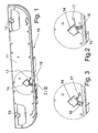
- the Indian FIG. 1 shown electromotive linear drive 10 is equipped with a two-part housing 11, which consists of two shells in the illustrated embodiment.
- the housing 11 is provided in the end regions with recesses 12, 13, which engage in the mounted state, the waves of the backrest and the foot part of a slatted frame.
- a shell 14 is attached, which has a slot-like opening 15 on the lower side, as particularly in the FIG. 2 can be seen.
- a handle in the form of a release lever 16 is pivotally mounted on an axis, not shown.
- the release lever 16 is designed so that so that a switchable clutch can be actuated, which is within the drive train of the electromotive linear drive.
- the decoupling or the disengagement of the clutch takes place against the action of a spring or against the action of several springs.
- the connection between the release lever 16 and the switchable coupling could be done for example by a linkage or by a Bowden cable.
- a blocking element in the form of a locking lever 17 is fixed.
- This locking lever is made of a spring steel section with a flat cross-section. As the figures show, it has a trigger lever 16 facing portion having an acute angle to the release lever 16. This section is followed by a shorter central part, which is also at an acute angle to the trigger lever 16 facing portion. This is followed an end portion that can be used as a handle or handle to operate the locking lever 17.
- FIG. 4 shows an electromotive linear drive, again two drive trains are used in a common housing 11.
- These drive trains consist of a drive motor, a coupled speed reducer, a spindle and the output member of the drive forming spindle nut and a disengaging unit with a clutch.
- the disengaging unit can be actuated by a handle 16, which is designed as a pivot lever and is attached externally to the housing.
- the disengaging unit is inserted in a multi-part shell-like housing part 14a and 14b. In this case, contrary to the representation, the shell-like housing part 14 b may be formed integrally with the housing 11 of the linear drive 10.
- FIG. 5 shows in an exploded view, the handle 16, the two shell-like housing 14a and 14b, a spring element 17a and a trained as a sliding element actuator 17b.
- the spring element 17a has two legs which are at an acute angle to each other, whose free end regions are angled in opposite directions. Furthermore, a pin 18 is provided, which is inserted into the actuating element 17b and is in operative connection with a not shown, movable coupling part of the respective drive train.
- the housing parts 14a, 14b are formed mirror-inverted with respect to the vertical center plane, so that it can be attached to the mirror image arranged drive trains. Furthermore, the shell-like housing parts 14a, 14b still have contours, latching noses and latching cutouts which correspond to each other, but engage at least partially in one another and lock in place during assembly.
- the spring element 17a is biased, so that the handle 16 and the sliding element 17b according to the FIG. 5 be pressed in their respective first end position.
- the handle 16 is actuated by according to the FIG. 5 is pivoted to the right, so first the spring element 17a is further tensioned until the imaginary line between the bent ends of the legs of the spring element 17a occupy an angle of about 90 ° to the axis of movement of the sliding element 17b.
- the handle 16 is pivoted further, the arrangement over a so-called dead point, so that the force of the spring can be divided into a force component, which points in the direction of the second end position of the sliding element 17b, so that the sliding member 17b in this second end position moved and held there by the force of the spring element 17a.
- the handle is then guided by the spring element, the handle in its second end position and held there under the spring preload described above.
- an imaginary line between the ends of the legs of the spring element 17a forms a second acute angle to the axis of movement of the sliding element 17b.
- the leg spring 17a is first to the dead point the arrangement stretched, so that the division of the forces of the spring element has a component in the direction of the first end position of the sliding element 17, whereupon the sliding element 17b is moved to the first end position and the handle is also moved back into the first end position.
- the housing parts 14a and 14b according to the FIG. 5 are formed mirror-inverted to the vertical center plane of the linear drive, the first acute angle with the second acute angle is the same. In another embodiment, however, the first acute angle and the second acute angle may be different.
- the housing 14a, 14b are then advantageously formed asymmetrically.
- FIG. 6 shows the handle in a first end position while the FIG. 7 the same handle 16 in the second end position shows.
- the cup-shaped housing parts 14a and 14b according to FIGS. 6 and 7 relative to the vertical center plane of the linear drive 10 are formed mirror-inverted and symmetrical, the angle of the handle 16 with respect to the vertical in both positions is the same.
- the invention is not limited to the illustrated embodiment. It is essential that an externally operable release lever 16 or other handle is held by means of a blocking element in the position in which the switchable clutch provided in the drive train is disengaged or disengaged. Furthermore, it is essential that the blocking element or the locking lever 17 automatically enters the blocking position when the release lever is actuated.
Landscapes
- Health & Medical Sciences (AREA)
- General Health & Medical Sciences (AREA)
- Nursing (AREA)
- Transmission Devices (AREA)
- Mechanical Operated Clutches (AREA)
Applications Claiming Priority (1)
| Application Number | Priority Date | Filing Date | Title |
|---|---|---|---|
| DE200520020266 DE202005020266U1 (de) | 2005-12-23 | 2005-12-23 | Elektromotorischer Linearantrieb |
Publications (2)
| Publication Number | Publication Date |
|---|---|
| EP1800567A1 EP1800567A1 (de) | 2007-06-27 |
| EP1800567B1 true EP1800567B1 (de) | 2010-04-21 |
Family
ID=37890865
Family Applications (1)
| Application Number | Title | Priority Date | Filing Date |
|---|---|---|---|
| EP20060126855 Active EP1800567B1 (de) | 2005-12-23 | 2006-12-21 | Elektromotorischer Linearantrieb |
Country Status (3)
| Country | Link |
|---|---|
| EP (1) | EP1800567B1 (da) |
| DE (2) | DE202005020266U1 (da) |
| DK (1) | DK1800567T3 (da) |
Cited By (1)
| Publication number | Priority date | Publication date | Assignee | Title |
|---|---|---|---|---|
| EP2845520A1 (de) | 2013-09-09 | 2015-03-11 | Dewertokin GmbH | Vorrichtung zur Steuerung eines Möbelantriebs |
Family Cites Families (6)
| Publication number | Priority date | Publication date | Assignee | Title |
|---|---|---|---|---|
| DE114888C (da) * | ||||
| FR680404A (fr) | 1929-08-17 | 1930-04-29 | Usine E J Conill | Dispositif d'embrayage des organes de commande des mouvements de la tourelle et du chariot dans les tours revolvers |
| CH346748A (de) * | 1958-02-24 | 1960-05-31 | Joos Carl | Steuervorrichtung für den Arbeitsspindel- und den Vorschubantrieb an Werkzeugmaschinen |
| DE29811566U1 (de) * | 1998-06-29 | 1998-08-20 | Dewert Antriebs- und Systemtechnik GmbH & Co KG, 32278 Kirchlengern | Elektromotorischer Möbelantrieb |
| DE10200169A1 (de) | 2002-01-04 | 2003-07-17 | Cimosys Ag Goldingen | Möbelantrieb zum Verstellen von Teilen eines Möbels relativ zueinander |
| DE20214426U1 (de) * | 2002-09-17 | 2004-02-19 | Cimosys Ag | Elektromotorischer Möbelantrieb zum Verstellen von Teilen eines Möbels relativ zueinander |
-
2005
- 2005-12-23 DE DE200520020266 patent/DE202005020266U1/de not_active Expired - Lifetime
-
2006
- 2006-12-21 DK DK06126855T patent/DK1800567T3/da active
- 2006-12-21 EP EP20060126855 patent/EP1800567B1/de active Active
- 2006-12-21 DE DE200650006775 patent/DE502006006775D1/de active Active
Cited By (2)
| Publication number | Priority date | Publication date | Assignee | Title |
|---|---|---|---|---|
| EP2845520A1 (de) | 2013-09-09 | 2015-03-11 | Dewertokin GmbH | Vorrichtung zur Steuerung eines Möbelantriebs |
| DE102013217920A1 (de) | 2013-09-09 | 2015-03-12 | Dewertokin Gmbh | Vorrichtung zur Steuerung eines Möbelantriebs |
Also Published As
| Publication number | Publication date |
|---|---|
| DE502006006775D1 (de) | 2010-06-02 |
| DK1800567T3 (da) | 2010-08-16 |
| EP1800567A1 (de) | 2007-06-27 |
| DE202005020266U1 (de) | 2007-04-26 |
Similar Documents
| Publication | Publication Date | Title |
|---|---|---|
| DE19527912C2 (de) | Beidseitig wirkender, manueller Antrieb zur Erzeugung einer Drehbewegung, insbesondere für Kraftfahrzeugsitze | |
| EP1288026B1 (de) | Anhängekupplung | |
| EP0807031B1 (de) | Beidseitig wirkender manueller antrieb zur erzeugung einer drehbewegung | |
| EP2217783B1 (de) | Antriebssytem für ein verschliessteil eines kraftfahrzeugs | |
| EP2777136B1 (de) | Linearantrieb für möbel | |
| DE202005002585U1 (de) | Elektromotorischer Linearantrieb | |
| WO2013068329A1 (de) | Elektromotorischer linearantrieb, insbesondere zum verstellen von liege- und sitzmöbeln | |
| DE10200169A1 (de) | Möbelantrieb zum Verstellen von Teilen eines Möbels relativ zueinander | |
| EP2869733B1 (de) | Vorrichtung zur steuerung eines möbelantriebs | |
| EP2060206A2 (de) | Möbelantrieb | |
| DE3118634A1 (de) | Verstellantrieb mit schlingfederbremselement in einem kraftfahrzeug, insbesondere fuer einen fensterheber | |
| EP1468631B1 (de) | Dämpfungsvorrichtung für bewegbare Möbelteile | |
| EP2891826A2 (de) | Elektromotorischer Linearantrieb | |
| DE10228891A1 (de) | Elektromotorischer Möbelantrieb | |
| DE102004009331B4 (de) | Betätigungsmechanismus für Bowdenzüge | |
| DE102005007205B3 (de) | Elektromotorischer Linearantrieb | |
| EP1853136B1 (de) | Verstellbares sitzmöbel | |
| DE102004016050B4 (de) | Elektromotorischer Möbelantrieb zum Verstellen von Teilen eines Möbels relativ zueinander | |
| DE4436096A1 (de) | Klinkenschaltwerk zum Antrieb von Verstellvorrichtungen für Fahrzeugsitze | |
| DE20214426U1 (de) | Elektromotorischer Möbelantrieb zum Verstellen von Teilen eines Möbels relativ zueinander | |
| EP1800567A1 (de) | Elektromotorischer Linearantrieb | |
| EP1057960B1 (de) | Stellvorrichtung | |
| DE19952633C1 (de) | Beidseitig wirkender Antrieb für Verstellvorrichtungen in Kraftfahrzeugen | |
| DE10200168A1 (de) | Elektromotorischer Möbelantrieb zum Verstellen von Teilen eines Möbels relativ zueinander | |
| DE10232184A1 (de) | Übertragungseinheit für Türschlösser von Kraftfahrzeugen |
Legal Events
| Date | Code | Title | Description |
|---|---|---|---|
| PUAI | Public reference made under article 153(3) epc to a published international application that has entered the european phase |
Free format text: ORIGINAL CODE: 0009012 |
|
| AK | Designated contracting states |
Kind code of ref document: A1 Designated state(s): AT BE BG CH CY CZ DE DK EE ES FI FR GB GR HU IE IS IT LI LT LU LV MC NL PL PT RO SE SI SK TR |
|
| AX | Request for extension of the european patent |
Extension state: AL BA HR MK YU |
|
| 17P | Request for examination filed |
Effective date: 20070803 |
|
| 17Q | First examination report despatched |
Effective date: 20071114 |
|
| AKX | Designation fees paid |
Designated state(s): DE DK FR GB NL |
|
| GRAP | Despatch of communication of intention to grant a patent |
Free format text: ORIGINAL CODE: EPIDOSNIGR1 |
|
| GRAS | Grant fee paid |
Free format text: ORIGINAL CODE: EPIDOSNIGR3 |
|
| GRAA | (expected) grant |
Free format text: ORIGINAL CODE: 0009210 |
|
| AK | Designated contracting states |
Kind code of ref document: B1 Designated state(s): DE DK FR GB NL |
|
| REG | Reference to a national code |
Ref country code: GB Ref legal event code: FG4D Free format text: NOT ENGLISH |
|
| REF | Corresponds to: |
Ref document number: 502006006775 Country of ref document: DE Date of ref document: 20100602 Kind code of ref document: P |
|
| REG | Reference to a national code |
Ref country code: NL Ref legal event code: T3 |
|
| REG | Reference to a national code |
Ref country code: DK Ref legal event code: T3 |
|
| PLBE | No opposition filed within time limit |
Free format text: ORIGINAL CODE: 0009261 |
|
| STAA | Information on the status of an ep patent application or granted ep patent |
Free format text: STATUS: NO OPPOSITION FILED WITHIN TIME LIMIT |
|
| 26N | No opposition filed |
Effective date: 20110124 |
|
| REG | Reference to a national code |
Ref country code: DE Ref legal event code: R082 Ref document number: 502006006775 Country of ref document: DE Representative=s name: LOESENBECK UND KOLLEGEN, DE |
|
| REG | Reference to a national code |
Ref country code: DE Ref legal event code: R082 Ref document number: 502006006775 Country of ref document: DE Representative=s name: LOESENBECK UND KOLLEGEN, DE Effective date: 20130729 Ref country code: DE Ref legal event code: R081 Ref document number: 502006006775 Country of ref document: DE Owner name: DEWERTOKIN GMBH, DE Free format text: FORMER OWNER: DEWERT ANTRIEBS- UND SYSTEMTECHNIK GMBH, 32278 KIRCHLENGERN, DE Effective date: 20130729 |
|
| REG | Reference to a national code |
Ref country code: NL Ref legal event code: TD Effective date: 20140305 |
|
| REG | Reference to a national code |
Ref country code: GB Ref legal event code: 732E Free format text: REGISTERED BETWEEN 20140306 AND 20140312 |
|
| REG | Reference to a national code |
Ref country code: FR Ref legal event code: CD Owner name: DEWERTOKIN GMBH, DE Effective date: 20140314 |
|
| REG | Reference to a national code |
Ref country code: FR Ref legal event code: PLFP Year of fee payment: 10 |
|
| REG | Reference to a national code |
Ref country code: FR Ref legal event code: PLFP Year of fee payment: 11 |
|
| REG | Reference to a national code |
Ref country code: FR Ref legal event code: PLFP Year of fee payment: 12 |
|
| PGFP | Annual fee paid to national office [announced via postgrant information from national office to epo] |
Ref country code: FR Payment date: 20171219 Year of fee payment: 12 Ref country code: NL Payment date: 20171219 Year of fee payment: 12 |
|
| PGFP | Annual fee paid to national office [announced via postgrant information from national office to epo] |
Ref country code: GB Payment date: 20171221 Year of fee payment: 12 |
|
| REG | Reference to a national code |
Ref country code: NL Ref legal event code: MM Effective date: 20190101 |
|
| GBPC | Gb: european patent ceased through non-payment of renewal fee |
Effective date: 20181221 |
|
| PG25 | Lapsed in a contracting state [announced via postgrant information from national office to epo] |
Ref country code: NL Free format text: LAPSE BECAUSE OF NON-PAYMENT OF DUE FEES Effective date: 20190101 |
|
| PG25 | Lapsed in a contracting state [announced via postgrant information from national office to epo] |
Ref country code: FR Free format text: LAPSE BECAUSE OF NON-PAYMENT OF DUE FEES Effective date: 20181231 |
|
| PG25 | Lapsed in a contracting state [announced via postgrant information from national office to epo] |
Ref country code: GB Free format text: LAPSE BECAUSE OF NON-PAYMENT OF DUE FEES Effective date: 20181221 |
|
| REG | Reference to a national code |
Ref country code: DE Ref legal event code: R082 Ref document number: 502006006775 Country of ref document: DE Representative=s name: PATENT- UND RECHTSANWAELTE LOESENBECK, SPECHT,, DE Ref country code: DE Ref legal event code: R081 Ref document number: 502006006775 Country of ref document: DE Owner name: DEWERTOKIN TECHNOLOGY GROUP CO., LTD., JIAXING, CN Free format text: FORMER OWNER: DEWERTOKIN GMBH, 32278 KIRCHLENGERN, DE |
|
| P01 | Opt-out of the competence of the unified patent court (upc) registered |
Effective date: 20230328 |
|
| PGFP | Annual fee paid to national office [announced via postgrant information from national office to epo] |
Ref country code: DE Payment date: 20241211 Year of fee payment: 19 |
|
| PGFP | Annual fee paid to national office [announced via postgrant information from national office to epo] |
Ref country code: DK Payment date: 20241125 Year of fee payment: 19 |