EP1800575B1 - Unité d'infusion - Google Patents
Unité d'infusion Download PDFInfo
- Publication number
- EP1800575B1 EP1800575B1 EP05425913A EP05425913A EP1800575B1 EP 1800575 B1 EP1800575 B1 EP 1800575B1 EP 05425913 A EP05425913 A EP 05425913A EP 05425913 A EP05425913 A EP 05425913A EP 1800575 B1 EP1800575 B1 EP 1800575B1
- Authority
- EP
- European Patent Office
- Prior art keywords
- chamber
- infusion
- mobile
- plate
- movement
- Prior art date
- Legal status (The legal status is an assumption and is not a legal conclusion. Google has not performed a legal analysis and makes no representation as to the accuracy of the status listed.)
- Expired - Lifetime
Links
Images


Classifications
-
- A—HUMAN NECESSITIES
- A47—FURNITURE; DOMESTIC ARTICLES OR APPLIANCES; COFFEE MILLS; SPICE MILLS; SUCTION CLEANERS IN GENERAL
- A47J—KITCHEN EQUIPMENT; COFFEE MILLS; SPICE MILLS; APPARATUS FOR MAKING BEVERAGES
- A47J31/00—Apparatus for making beverages
- A47J31/24—Coffee-making apparatus in which hot water is passed through the filter under pressure, i.e. in which the coffee grounds are extracted under pressure
- A47J31/34—Coffee-making apparatus in which hot water is passed through the filter under pressure, i.e. in which the coffee grounds are extracted under pressure with hot water under liquid pressure
- A47J31/36—Coffee-making apparatus in which hot water is passed through the filter under pressure, i.e. in which the coffee grounds are extracted under pressure with hot water under liquid pressure with mechanical pressure-producing means
- A47J31/3604—Coffee-making apparatus in which hot water is passed through the filter under pressure, i.e. in which the coffee grounds are extracted under pressure with hot water under liquid pressure with mechanical pressure-producing means with a mechanism arranged to move the brewing chamber between loading, infusing and ejecting stations
- A47J31/3609—Loose coffee being employed
Definitions
- the present invention refers to an infusion unit for infusion preparation, to an infusion machine and to the method for making the infusion unit.
- the present invention refers to a unit for the so-called vertical type superautomatic machines having a device for ejecting exhausted ground coffee, to the corresponding vertical type machine and to the method for making the infusion unit.
- the present invention is also meant to be applicable to horizontal type infusion machines, in which, as known, the tamping is made along a substantially horizontal axis, or to machines having an intermediate orientation between vertical and horizontal axis.
- Infusion machines and units for infusion preparation are known in the art.
- machines are known, for instance vertical type superautomatic machines, that comprise devices for the ejection of already exhausted infusion powders.
- a device for the ejection of already exhausted ground coffee and applied to a coffee preparation vertical machine is known from Publication EP_0528758 .
- the known machine comprises two opposed pistons, an upper piston that is stationary and a lower one, a cylinder associated to the lower piston and apt to form a chamber with it, and an ejection arm having a first end pivoted to the cylinder.
- the cylinder guided by a rotary shaft having a rotary axis outside of the cylinder, pulls the lower piston in the direction of the stationary piston so as to realise an infusion chamber formed by the stationary piston, the cylinder and the lower piston.
- the cylinder After the tamping of the ground coffee and the corresponding infusion by means of water flow in pressure, the cylinder is guided in a direction opposite to the stationary piston by pulling the lower piston itself with it and holding the ejection arm in a rest position.
- the rigid type ejection arm which has a spatula of concave shape at a second end, is activated and set into an arc motion (pendulum type motion) around a pivot so as to eject the exhausted powder that is on the piston convex head.
- the ejection arm comprises a lever that protrudes from the pivot wherein the first end is pivoted so that a first protruding element, fixed to the base of the frame, at the end of the cylinder movement, is capable to activate the rotation of the lever and of the ejection arm connected to it.
- the lever runs into a second protruding element, fixed to a side of the frame, arranged to force a rotation in the opposed direction of the lever and of the arm so as to restore the rest position of the ejection arm.
- the ejection mechanism comprises elements associated to the cylinder: the arm, the pivot and the lever; elements associated to the base of the frame: a first protruding element; elements associated to the sides of the frame: a second protruding element; all elements that, being associated to various parts of the machine, make complex a calibration of the device that might be necessary, for instance, due to the wear and tear of protruding elements and/or of the lever that co-operates with protruding elements and/or of the spatula.
- Such a problem obviously, is worsened by the fact that the area wherein the lever and the protruding elements work typically comprises ground coffee mixed with water which is, as known, strongly abrasive.
- a further problem of such a prior art is that it requires to shape the piston with a convex head and the cylinder, analogously, with convex edges, in order to avoid that exhausted ground coffee is accumulated on the piston head and/or on the cylinder edges.
- a curved shape of the piston head is not optimal for obtaining a uniformly distributed pressure on the infusion powder and therefore for obtaining a good infusion.
- a further more general problem of such a type of prior art is related to the fact that the cylinder and piston movement is operated by means of devices being not in axis thereto so that the acting forces typically are not balanced and this causes wear and tear of the moving parts, similarly not balanced.
- Object of the present invention is an infusion unit for infusion machine suitable for solving the above problems in a simple, effective way, and such so to avoid possible wear and tear due to powder and liquids present in the machine. Further object of the present invention is a device for exhausted powder ejection simple to realise and suitable to allow use of pistons having a flat head. Another object of the present invention is an infusion unit and corresponding machine in which the movement of mobile elements, as chamber and piston, is controlled axially with respect to the same chamber and piston.
- the infusion unit comprises, in addition to a mobile infusion chamber, a plate resiliently linked to the infusion chamber so that such a resilient link is apt either to induce the movement of the chamber into the infusion unit or to allow relative movement between chamber and plate.
- the infusion unit comprises an ejection device that is mechanically activated by the relative movement between chamber and plate for ejecting the exhausted powder.
- the movement of the plate and of the associated chamber is obtained by means of devices located in barycentric position as to the plate and the chamber.
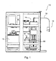
- a machine suitable for the preparation of infusions for instance a vertical type superautomatic machine for espresso coffee preparation, whereto from now on reference is made for description convenience, comprises a boiler 12, of known type, apt to heat and hold in pressure a determined amount of liquid as for instance water, an infusion unit 14, and at least a supplying spout 15.
- the supplying spout 15, of known type, is connected to the infusion unit by means of ducts 18 and is apt to supply the infusion in one or more coffee mugs or cups as a result of the infusion preparation by the infusion unit 14.
- the infusion unit 14 is connected, in a known way, to the boiler 12 and is suitable to receive pressurised hot water from the boiler 12 through ducts 19, for instance flexible ducts of known type, and to prepare, for instance, a coffee infusion, by means of a generic infusion cycle, which is now described and kept as reference for description convenience, and which will be detailed later on in the description of the machine 10 operation.
- the generic infusion cycle comprises, for instance, the following steps:
- the infusion unit (unit) 14 comprises, in the preferred embodiment, first of all, a first piston 43, for instance a stationary type piston (Figg. 2, 3, 4) and a frame (unit frame) 41 apt to support, in a known way, several components or devices of the unit 14 and the first piston (stationary piston) 43.
- the frame also comprises a plurality of studs (vertical rods) 61, having for instance a circular cross-section, and apt to guide the movement of several mobile components or devices of the unit 14, as it is disclosed hereafter in detail.
- the stationary piston 43 comprises a filter 33 and an inner duct 38 linked to the ducts 18 connected to the supplying spout 15 ( Fig. 1 ).
- the stationary piston 43 preferably, is shaped so as to transfer during the infusion step the infusion from the infusion unit to the supplying spout 15.
- the unit 14 further comprises a motor 66 and a mobile plate (plate) 45 (Figg. 1, 2, 3, 4) apt to be reciprocated by the motor 66.
- the plate being for instance of rectangular shape comprises a plurality of cavities 53 ( Fig. 5 ) located at the top ends of the plate 45 and coupled to the studs 61 (Figg. 1, 2, 3, 4); the cavities 53 are arranged so as to allow sliding of the plate 45 along studs 61 of the frame 41.
- the mobile plate 45 further comprises a coupling element 55 which, in the preferred embodiment, is barycentric to the plate 45 and associated to a worm screw 65, which is barycentric to the plate 45, too, and operated in a known way by the motor 66 through a coupling gear.
- the mobile plate 45 is apt, according to the present exemplary embodiment, to be reciprocated along the studs 61 so as to allow the execution of the several steps of the infusion cycle, as it will be disclosed later on in detail.
- the motor 66 for instance an electric motor of known type, is controlled, in a known way, so as to rotate the worm screw 65 clockwise or counter-clockwise and, in the preferred embodiment, is associated to a current absorption detector 67 adapted to determine motor locking if a predetermined overcurrent absorption is determined by the motor 66.
- the unit 14 comprises, also, an infusion chamber 46 and a second piston 48, both, for instance, of mobile type.
- the infusion chamber (mobile chamber) 46 comprises, in the preferred embodiment, three resilient elements 71, triangularly arranged around the second piston 48 and in barycentric position as to the plate 45 and the chamber 46; the resilient elements 71 are of a determined rigidity and are shaped so as to mechanically link the mobile plate 45 to the mobile chamber 46.
- the resilient elements 71 comprise, for instance, cylindrical pression springs of known type housed in suitable seats, of known type, that provide spring pression in only one direction; moreover the chamber 46 comprises, for instance, cavities 63 ( Fig. 5 ) apt to allow the sliding of the chamber itself along the studs 61 (Figg. 1, 2, 3, 4) of the frame 41.
- the mobile chamber (chamber) 46 thanks to the link realised by the resilient elements (springs) 71, is apt to be guided in the movement by the mobile plate 45 so that the reciprocating movement of the mobile plate 45 mostly induces the movement of the mobile chamber 46 during the infusion cycle, as it will be disclosed later on in detail.
- the mobile chamber 46 comprises an inner surface 72, preferably of cylindrical cross-section, and an upper surface 73, which is, preferably, a flat surface associated, at one side of the chamber 46, to one or more draining conducts 75, known per se, and aligned thereto.
- the mobile chamber 46 also comprises a support element 78, of known type, apt to support and to move the mobile piston 48 mostly together with the movement of the mobile chamber during the infusion cycle, as it will be disclosed later on in detail, and a feeding annular chamber 74, of known type, connected to the boiler 12 through the ducts 19 and apt to feed the mobile piston 48 with pressurised hot water during the infusion step.
- the mobile chamber 46 comprises, preferably associated to the support element, a first stop element (first stop) 79, apt to limit, as it will be disclosed later on in detail, the movement of the mobile piston 48 as to the mobile chamber 46, when provided during the infusion cycle.
- the mobile piston 48 concentric to the mobile chamber, comprises, in the preferred embodiment, a head 80, of known type, and a rod 85, that in the preferred embodiment, is cylindrically shaped and on axis with the worm screw 65.
- the rod has a first end fixed to the head 80 in its barycentric position and a second end associated to a second stop element (second stop) 89 apt to limit, as it will be disclosed later on in detail, both the movement of the mobile piston 48 as to the mobile chamber 46 and the movement of the mobile chamber 46 itself, when provided in the infusion cycle.
- the head 80 comprises a filter 83, of known type, and is connected, in known way, to the feeding annular chamber 74 being in turn connected to the boiler 12.
- the rod 85 is associated to a resilient element 81, for instance a cylindrical pressure spring of known type having a first end fixed to the first stop 79 and a second end fixed to the second stop 89;
- the resilient element (spring) 81, associated to the mobile piston 48 has as a whole, in the preferred embodiment, a lower rigidity than the total rigidity of the springs 71 associated to the mobile chamber 46 and is shaped so as to allow the relative movement of the mobile piston 48 as to the mobile chamber 46, when provided in the infusion cycle, though ensuring, thanks to the rigidity difference, the movement of the mobile chamber 46 in together with the mobile plate 45.
- the mobile piston 48 is apt to tamp the powder, inside the mobile chamber 46 and with the aid of stationary piston 43, for obtaining the infusion.
- the mobile piston 48 is also apt, during the relative movement as to the mobile chamber 46, to prepare the exhausted powder for the ejection, as it will be disclosed later on in detail.
- the infusion unit 14 comprises a mechanical ejection device (ejection device) 49 apt to eject the exhausted powder from the unit 14 itself.
- the ejection device 49 is shaped, in the preferred embodiment, as a lever having a fulcrum 91 ( Fig. 5 ) and an acting and a resisting arm, respectively 93 and 97, and is apt to shift from a first position (rest position) to a second position (ejection position) following an acting force applied to the acting arm.
- the fulcrum 91 is pivoted by means of a first pivot 96 to a wall 47 fixed to or comprised in the mobile chamber 46; the acting arm or first arm 93, to which the acting force is applied, is pivoted, by means of a second pivot 95 to the plate 45; the resistant arm or second arm 97 is associated to a spatula 99 shaped so as to eject the exhausted powder.
- the relative movement of the mobile plate 45 as to the mobile chamber 46 movement which is possible, as it will be disclosed later on in detail, thanks to the springs 71 (Figg. 4, 5), is apt to apply the acting force to the first arm 93 so as to cause the movement along a circumferential arc of the second arm 97 associated to the spatula 99.
- the spatula 99 comprises a scraper element 100, apt to actually eject the exhausted powder, and first and second sliding elements, respectively 109 and 106.
- the second arm 97 comprises a cavity 107, longitudinal to the direction of the arm 97;
- the first sliding elements 109 for instance rollers of known type, are shaped so as to slide into the cavity 107 and arranged to disengage or to set as not rigid the link between the spatula 99 and the arm 97 and to allow a limited excursion in longitudinal direction of the spatula 99 as to the arm 97.
- the mobile chamber 46 comprises or is associated to a wall having a cavity 76, preferably an horizontal one, and the seconds sliding elements 106, for instance a roller of known type, are shaped so as to slide into the horizontal cavity 76.
- the combination of the cavity 107 in the arm 97 and of the cavity 76 associated to the mobile chamber 46 with the sliding elements, respectively 109 and 106, of the spatula 99 is apt to determine, as easily comprehensible to a technician in the field, a substantially horizontal movement of spatula 99 and, consequently, of the scraper element 100 during the movement of the second arm 97.
- the scraper element 100 comprises a covering or brush 100a and a rigid component 100b placed in sequence at the end of the second arm 97.
- the covering 100a is apt to contact, mostly, the mobile piston surface 48, and the rigid component 100b is apt to contact, mostly, the exhausted powder during the ejection of the ground coffee already exhausted, so that the covering 100a has a prevailing function of superficial cleaning of the piston and the rigid component 100b has a prevailing function of ejection.
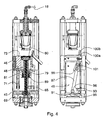
- a first step exemplified in Fig. 2
- the plate 45, the chamber 46 and the mobile piston 48 are in a relative fixed and determined position, and the stationary piston 43 is located at a predetermined distance from the upper surface 73 of the chamber 46 whereby it is possible, through load devices of known type, to insert a determined amount of infusion powder in the cavity obtained by means of the chamber 46 and the mobile piston 48.
- the springs 71 between plate 45 and chamber 46 and the spring 81 associated to the mobile piston 48 are at rest.
- a second step infusion step
- the plate 45, the chamber 46 and the mobile piston 48 are moved in the direction of the stationary piston 43, by maintaining a relative fixed and determined position, because, as easily comprehensible to a technician in the field, the springs 71 and the spring 81 are not subject to any compressive stress.
- Such a step may be described as the combination of two elementary steps, firstly a tamping step and secondly a real infusion step.
- the mobile piston 48 is moved by the chamber 46 by means of the support element 78 in the direction of the stationary piston 43 so as to realise a closed cavity or infusion chamber delimited by the inner surface 72 of the chamber 46 and by the stationary and mobile pistons, 43 an 48 respectively.
- the springs 71 between the plate 45 and the chamber 46, and the spring 81 associated to the mobile piston 48 are at rest.
- the movement of the plate 45, the chamber 46 and the mobile piston 48 ends when, as a result of the tamping exerted on the infusion powder, the current absorption detector 67 (Figg.
- a third step exemplified in Fig. 4
- the plate 45, the chamber 46 and the mobile piston 48 are moved in an opposite direction to the stationary piston 43 position.
- Such a step may be described as the combination of three elementary steps in sequence: a first and second elementary steps of movement away from the stationary piston 43 and a third step of actual exhausted powder ejection.
- the motor 66 after inversion of the rotational motion, moves the plate 45 in an opposite direction to the stationary piston 43 position.
- the plate 45, the chamber 46 and the mobile piston 48 maintain a relative fixed and determined position and the springs 71 and the spring 81 are not subject to any compressive stress.
- the first movement away step ends when the head 80 of the mobile piston abuts against the worm screw 65, whereby the movement of the mobile piston 48 is stopped.
- the second movement away step being the rigidity of the spring 81 lower than that of the springs 71 linking the plate 45 and the chamber 46, the plate 45 and the chamber 46 continue their movement, while the spring 81 is compressed and a corresponding movement of the mobile piston 48 relative to the chamber 46 is started.
- Such a relative movement is apt to make the exhausted powder tablet emerge from the upper surface 73 of the chamber 46 .
- the second movement away step ends when the first stop 79, associated to the chamber 46, comes in contact with and is stopped by the second stop 89 associated to the mobile piston 48; such a condition corresponds to the alignment of the head 80 of mobile piston 48 to the upper surface 73 of the chamber 46.
- the motor 66 continues to move the plate 45 while the chamber 46, being blocked by the stops, 79 and 89, in contact, is apt to compress the springs 71 linking the plate 45 and the chamber 46 whereby inducing or activating a corresponding movement between the plate 45 and the chamber 46; the corresponding relative movement applies the acting force to the first arm 93 and causes the movement of the second arm 97 and of the associated spatula 99, i.e.
- the shift of the ejection device 49 from the rest position to the ejection position is apt to cause the ejection of the exhausted powder tablet from the head 80 of the mobile piston 48.
- the movement of the plate 45 continues until a micro-switch 69 is reached; the micro-switch is provided at the bottom of the frame 41 for blocking the motor 66 (Figg. 1 and 4) and, if necessary, for inverting its rotational motion; such an operation put an end to the ejection step.
- the infusion cycle can start again after a first elementary movement step of the plate 45 in the direction of the stationary piston 43 adapted to sequentially carry in a rest position, the springs 71, linking the plate 45 and the chamber 46, and the spring 81 associated to the mobile piston 48.
- a first elementary movement step of the plate 45 in the direction of the stationary piston 43 adapted to sequentially carry in a rest position, the springs 71, linking the plate 45 and the chamber 46, and the spring 81 associated to the mobile piston 48.
- the machine and the infusion unit have been described above taking as reference a vertical type machine wherein the supplying spout is connected to the stationary piston.
- the supplying spout can also be connected to the mobile piston and the boiler to the stationary piston and the liquid flow can be reversed as compared to that above described.
- the infusion unit has been described by taking as reference a resilient link between the mobile plate and the mobile chamber realised through triangularly arranged resilient elements.
- the number of resilient elements can be lower or higher than three and the position of resilient elements can be barycentric to the plate and to the chamber, solution that is the preferred one for requirements associated to mechanical wear of mobile parts, or not barycentric.
- the resilient elements, linking the plate and the chamber, and the resilient element, associated to the piston have been described as cylindrical pressure springs.
- the resilient elements may also be of different type and also comprise, for instance, without departing from the scope of the above description, materials, having reversible elasticity, such as rubber.
- the ejection device comprises a resisting arm and a spatula linked in such a way as to obtain a substantially horizontal movement of the spatula.
- the arm and the spatula may be differently linked, though obtaining the same result, or may also be rigidly linked.
- the stop of the plate moving away from the stationary piston is determined by a micro-switch.
- the stop may also be determined by measuring a possible over-current absorbed by the motor or differently, without departing from the scope of the above description. The same considerations, obviously, are also applicable to determine the completion of the tamping step.
Landscapes
- Engineering & Computer Science (AREA)
- Mechanical Engineering (AREA)
- Food Science & Technology (AREA)
- Apparatus For Making Beverages (AREA)
- Soy Sauces And Products Related Thereto (AREA)
- Infusion, Injection, And Reservoir Apparatuses (AREA)
- External Artificial Organs (AREA)
Claims (12)
- Unité d'infusion destinée à une préparation d'infusion, en particulier un café « expresso », au moyen d'une poudre pour infusion, comportant :- un piston fixe (43), une chambre mobile (46) et un piston mobile (48) concentrique à la chambre mobile, capables de coopérer en vue de la préparation de ladite infusion au moyen de ladite poudre et de générer une pastille de poudre utilisée, ledit piston mobile (48) étant agencé en vue de se déplacer par rapport à la chambre mobile (46) de façon à préparer ladite pastille de poudre utilisée pour être éjectée de ladite unité d'infusion par un dispositif d'éjection activé mécaniquement (49) ;caractérisée en ce que- ladite unité d'infusion comporte une plaque (45) associée aux moyens de déplacement (55, 65, 66) agencés pour déplacer ladite plaque,- ladite chambre comprend au moins un élément de liaison élastique (71) présentant une rigidité déterminée et disposé pour relier ladite chambre à ladite plaque afin d'induire le déplacement de ladite chambre avec ladite plaque et pour permettre un déplacement relatif de ladite chambre par rapport à ladite plaque, et- ledit dispositif d'éjection est activé mécaniquement par le déplacement relatif de ladite plaque par rapport à ladite chambre.
- Unité d'infusion (14) selon la revendication 1, caractérisée en ce que lesdits moyens de déplacement (55, 65, 66) sont barycentriques avec ladite plaque (45) et en ce que ladite chambre (46) est placée de façon barycentrique par rapport à ladite plaque.
- Unité d'infusion (14) selon la revendication 1 ou 2, caractérisée en ce que ledit dispositif d'éjection (49) est configuré comme un levier comportant :- un bras d'actionnement (93) pivotant vers ladite chambre au moyen d'un premier pivot (96) et vers ladite plaque au moyen d'un second pivot (95), et- un bras de résistance (97) agencé en vue d'éjecter ladite pastille de poudre utilisée.
- Unité d'infusion (14) selon la revendication 3, caractérisée en ce que ledit premier pivot (96) est le point d'appui dudit levier.
- Unité d'infusion (14) selon la revendication 3, caractérisée en ce que ladite chambre comprend une première cavité (76) perpendiculaire au déplacement de ladite chambre, et ledit bras de résistance (97) comporte une seconde cavité (107) longitudinale au bras de résistance, et en ce que ledit bras de résistance est associé à une spatule (99) comportant des moyens de coulissement agencés pour coulisser dans ladite première cavité (76) et dans ladite seconde cavité (107) et pour déterminer un déplacement rectiligne de ladite spatule.
- Unité d'infusion (14) selon l'une quelconque des revendications précédentes, caractérisée en ce que ledit piston mobile (48) comporte :- au moins un élément élastique (81) configuré pour permettre ledit déplacement relatif dudit piston mobile par rapport à la chambre mobile pour préparer la pastille de poudre utilisée afin qu'elle soit éjectée de ladite unité d'infusion, ledit au moins un élément élastique (81) présentant une rigidité inférieure à la rigidité dudit au moins un élément de liaison élastique (71).
- Unité d'infusion (14) selon l'une quelconque des revendications précédentes, caractérisée en ce que lesdits moyens de déplacement (65) comportent des moyens de butée agencés pour bloquer le déplacement dudit piston mobile (48) de sorte que ledit piston mobile (48) est disposé pour se déplacer par rapport à la chambre mobile (46).
- Unité d'infusion (14) selon l'une quelconque des revendications précédentes, caractérisée en ce que ledit, au moins un, élément de liaison élastique (71) comporte trois éléments élastiques (71) disposés en triangle et ayant la chambre mobile comme barycentre.
- Unité d'infusion (14) selon l'une quelconque des revendications précédentes caractérisée par le fait d'être une unité d'infusion de type vertical.
- Machine servant à la préparation d'une infusion, en particulier d'un café « expresso », au moyen d'une poudre pour infusion, comprenant au moins une unité d'infusion selon les revendications 1 à 9, au moins une chaudière (12) connectée en entrée à ladite au moins une unité d'infusion et agencée pour envoyer un liquide destiné à la préparation de ladite infusion vers ladite, au moins une, unité d'infusion, et au moins un dispositif de distribution (15) connecté en sortie à ladite, au moins une, unité d'infusion et agencé pour fournir ladite infusion.
- Procédé permettant de réaliser une unité d'infusion servant à la préparation d'une infusion, en particulier d'un café « expresso », au moyen d'une poudre pour infusion, comprenant l'étape consistant à :- fournir un piston fixe (43), une chambre mobile (46) et un piston mobile (48) concentrique à la chambre mobile, agencés en vue de coopérer pour la préparation de ladite infusion au moyen de ladite poudre et en vue de générer une pastille de poudre utilisée, ledit piston mobile (48) étant agencé en vue de se déplacer par rapport à la chambre mobile afin de préparer ladite tablette de poudre utilisée à être éjectée de ladite unité d'infusion par un dispositif d'éjection (49) activé mécaniquement ; etcaractérisé par les étapes consistant à :- fournir une plaque (54) associée aux moyens de déplacement (55, 65, 66) agencés en vue de déplacer ladite plaque,- fournir au moins un élément de liaison élastique (71) présentant une rigidité déterminée pour relier ladite chambre à ladite plaque de façon à induire le déplacement de ladite chambre avec ladite plaque et pour permettre un déplacement relatif de ladite chambre par rapport à ladite plaque, et- fournir un dispositif d'éjection agencé pour être activé mécaniquement par le déplacement relatif de ladite plaque par rapport à ladite chambre.
- Procédé selon la revendication 11, caractérisé par l'étape consistant à :- fournir des moyens de butée associés aux dits moyens de déplacement (65) et agencés en vue de bloquer le déplacement dudit piston mobile (48), de sorte que ledit piston mobile (48) est agencé pour se déplacer par rapport à la chambre mobile (46).
Priority Applications (7)
| Application Number | Priority Date | Filing Date | Title |
|---|---|---|---|
| AT05425913T ATE423495T1 (de) | 2005-12-23 | 2005-12-23 | Brühvorrichtung |
| DE602005012979T DE602005012979D1 (de) | 2005-12-23 | 2005-12-23 | Brühvorrichtung |
| PT05425913T PT1800575E (pt) | 2005-12-23 | 2005-12-23 | Unidade de infusão |
| ES05425913T ES2323078T3 (es) | 2005-12-23 | 2005-12-23 | Unidad de infusion. |
| EP05425913A EP1800575B1 (fr) | 2005-12-23 | 2005-12-23 | Unité d'infusion |
| US12/158,901 US8225709B2 (en) | 2005-12-23 | 2006-12-21 | Infusion unit for infusion preparation, infusion machine, device for ejection of exhausted infusion powder and method for making the same |
| PCT/IB2006/054995 WO2007072453A1 (fr) | 2005-12-23 | 2006-12-21 | Unite de perfusion pour une preparation de perfusion, machine a perfusion, dispositif pour le rejet de la poudre de perfusion epuisee et procede de fabrication. |
Applications Claiming Priority (1)
| Application Number | Priority Date | Filing Date | Title |
|---|---|---|---|
| EP05425913A EP1800575B1 (fr) | 2005-12-23 | 2005-12-23 | Unité d'infusion |
Publications (2)
| Publication Number | Publication Date |
|---|---|
| EP1800575A1 EP1800575A1 (fr) | 2007-06-27 |
| EP1800575B1 true EP1800575B1 (fr) | 2009-02-25 |
Family
ID=36129688
Family Applications (1)
| Application Number | Title | Priority Date | Filing Date |
|---|---|---|---|
| EP05425913A Expired - Lifetime EP1800575B1 (fr) | 2005-12-23 | 2005-12-23 | Unité d'infusion |
Country Status (7)
| Country | Link |
|---|---|
| US (1) | US8225709B2 (fr) |
| EP (1) | EP1800575B1 (fr) |
| AT (1) | ATE423495T1 (fr) |
| DE (1) | DE602005012979D1 (fr) |
| ES (1) | ES2323078T3 (fr) |
| PT (1) | PT1800575E (fr) |
| WO (1) | WO2007072453A1 (fr) |
Families Citing this family (16)
| Publication number | Priority date | Publication date | Assignee | Title |
|---|---|---|---|---|
| MX2008003736A (es) | 2005-04-11 | 2009-01-29 | Starbucks Corp | Maquina para preparar una bebida, tal como el cafe, y metodo relacionado. |
| WO2007027206A2 (fr) | 2005-04-11 | 2007-03-08 | Coffee Equipment Company | Machine pour infuser une boisson comme du café et procédé s'y rapportant |
| FR2889931B1 (fr) * | 2005-08-31 | 2007-11-02 | Seb Sa | Machine pour preparer une infusion |
| DE202007005791U1 (de) * | 2007-04-21 | 2008-08-21 | Wik Far East Ltd. | Brüheinheit für eine Kaffeemaschine sowie Kaffeemaschine mit einer solchen Brüheinheit |
| EP2042062B1 (fr) * | 2007-09-25 | 2010-04-14 | Schaerer AG | Dispositif-infuseur pour une machine à café |
| BRPI0909236A8 (pt) * | 2008-03-24 | 2019-02-12 | Bunn O Matic Corp | sistema fermentador com mecanismo de fermentação ativa e compressão de pistão de reservatório de amortecedor de substância de fermentação |
| IT1393999B1 (it) * | 2009-04-01 | 2012-05-17 | Rancilio Macchine Caffe | Macchina per la preparazione di infusi, in particolare caffe' espresso, gruppo erogatore e metodo di realizzazione della stessa |
| US9060645B2 (en) * | 2010-02-02 | 2015-06-23 | Uniterra, Inc. | Beverage brewing device and method |
| RU2012141643A (ru) * | 2010-03-01 | 2014-04-10 | Конкордиа Коффи Компани, Инк. | Устройство ускоренного заваривания при низком давлении |
| EP2680726B1 (fr) * | 2011-03-04 | 2017-09-13 | Bunn-O-Matic Corporation | Dispositif de percolation à activation de force de compactage |
| ITRM20110458A1 (it) * | 2011-09-05 | 2013-03-06 | Iacobucci Hf Electronics S P A | Dispositivo porta-cialda per macchina erogatrice di bevande |
| ITTO20110819A1 (it) | 2011-09-14 | 2013-03-15 | Lavazza Luigi Spa | Dispositivo per la preparazione di bevande e relativo procedimento |
| WO2013116056A1 (fr) | 2012-01-24 | 2013-08-08 | Bunn-O-Matic Corporation | Appareil d'infusion |
| BR102014018479B1 (pt) * | 2014-07-28 | 2022-02-01 | B.Blend Máquinas E Bebidas S.A. | Conjunto de movimentação de êmbolo |
| US20160194587A1 (en) * | 2015-01-02 | 2016-07-07 | Brian Ellegood | Brewing, fermenting, and service kettle keg with compression displacement plate |
| IT201600096912A1 (it) * | 2016-09-27 | 2018-03-27 | De Longhi Appliances Srl | Macchina da caffè con sistema di movimentazione migliorato del cilindro di infusione |
Family Cites Families (5)
| Publication number | Priority date | Publication date | Assignee | Title |
|---|---|---|---|---|
| IT1250447B (it) * | 1991-07-03 | 1995-04-07 | Lucio Grossi | Macchina automatica per la produzione di caffe' con azionamento a motore in corrente continua e viti senza fine. |
| CA2092909C (fr) * | 1991-07-30 | 2000-11-21 | Andre Lussi | Dispositif d'ejection du «gateau» de cafe moulu forme dans l'infuseur d'une machine a cafe |
| IT1262342B (it) * | 1993-12-20 | 1996-06-19 | G3 Ferrari Srl | Macchina automatica per fare caffe' espresso o bevande analoghe. |
| US5406882A (en) * | 1994-03-30 | 1995-04-18 | Shaanan Holdings Inc. | Brewer |
| US6205909B1 (en) * | 1997-09-05 | 2001-03-27 | Moulinex S.A. | Brewing unit for automatic beverage dispensers comprising in particular a boiler |
-
2005
- 2005-12-23 EP EP05425913A patent/EP1800575B1/fr not_active Expired - Lifetime
- 2005-12-23 ES ES05425913T patent/ES2323078T3/es not_active Expired - Lifetime
- 2005-12-23 PT PT05425913T patent/PT1800575E/pt unknown
- 2005-12-23 DE DE602005012979T patent/DE602005012979D1/de not_active Expired - Lifetime
- 2005-12-23 AT AT05425913T patent/ATE423495T1/de not_active IP Right Cessation
-
2006
- 2006-12-21 WO PCT/IB2006/054995 patent/WO2007072453A1/fr not_active Ceased
- 2006-12-21 US US12/158,901 patent/US8225709B2/en not_active Expired - Fee Related
Also Published As
| Publication number | Publication date |
|---|---|
| PT1800575E (pt) | 2009-05-14 |
| US8225709B2 (en) | 2012-07-24 |
| ES2323078T3 (es) | 2009-07-06 |
| DE602005012979D1 (de) | 2009-04-09 |
| WO2007072453A1 (fr) | 2007-06-28 |
| ATE423495T1 (de) | 2009-03-15 |
| EP1800575A1 (fr) | 2007-06-27 |
| US20080264266A1 (en) | 2008-10-30 |
Similar Documents
| Publication | Publication Date | Title |
|---|---|---|
| EP1800575B1 (fr) | Unité d'infusion | |
| KR102269856B1 (ko) | 음료를 준비하기 위한 장치 및 처리 공정과 이러한 장치를 포함하는 음료 분배 기계 | |
| CN108143278B (zh) | 用于在波塔过滤器内对一定剂量的咖啡加压的设备 | |
| JP7388792B2 (ja) | エスプレッソマシン及びコーヒーマシン用の抽出装置ならびにそれを備えたエスプレッソ及びコーヒーマシン | |
| RU2604015C2 (ru) | Инфузионный блок для кофеварки | |
| DK2858538T3 (en) | Delivery unit for machines for making beverages through capsules | |
| EP0298547A2 (fr) | Machine automatique compacte pour la production de café et d'infusions, en particulier pour l'usage domestique | |
| ITTO20090603A1 (it) | Macchina per la preparazione di bevande mediante infusione di un prodotto contenuto in una capsula o simile | |
| ITFI20070188A1 (it) | "gruppo di infusione per la preparazione di bevande e macchina comprendente detto gruppo di infusione" | |
| ITPN20070049A1 (it) | "gruppo infusore" | |
| EP3592195B1 (fr) | Ensemble pour distribuer des agents de lavage pour une machine à laver, en particulier un lave-vaisselle | |
| KR20030020962A (ko) | 이동식 달임실을 갖추고 장비 없이 분해가능한 퍼콜레이터그룹 | |
| CN114190772A (zh) | 配备有咖啡磨粉排出装置的自动咖啡机 | |
| JP2023530819A (ja) | 電動式抽出装置 | |
| US8770092B2 (en) | Brewing unit for a coffee machine | |
| CN103120545B (zh) | 烧煮组件 | |
| ITMI972377A1 (it) | Apparecchiatura per la preparazione di un infuso di caffe' | |
| EP1800573B1 (fr) | Dispositif constitué d'une pluralité d'unités de breuvage pour la préparation de café expresso | |
| CN110384400B (zh) | 用于使用包含食品物质的胶囊或容器来制作饮料的设备 | |
| EP3094220B1 (fr) | Unité d'infusion | |
| ITTO20000941A1 (it) | Macchina per caffe' espresso. | |
| RU9680U1 (ru) | Устройство для переработки зерна | |
| ITRM20040173U1 (it) | Dispositivo per la espulsione automatica dei discoidi utilizzati nelle macchine per la erogazione del caffe' od altre bevande similari. | |
| IT8322429A1 (it) | Macchina per il caffè-espresso | |
| ITMI20100452A1 (it) | Dispositivo erogatore per macchine a cialde e simili per infusi, particolarmente per la produzione di caffe' espresso. |
Legal Events
| Date | Code | Title | Description |
|---|---|---|---|
| PUAI | Public reference made under article 153(3) epc to a published international application that has entered the european phase |
Free format text: ORIGINAL CODE: 0009012 |
|
| AK | Designated contracting states |
Kind code of ref document: A1 Designated state(s): AT BE BG CH CY CZ DE DK EE ES FI FR GB GR HU IE IS IT LI LT LU LV MC NL PL PT RO SE SI SK TR |
|
| AX | Request for extension of the european patent |
Extension state: AL BA HR MK YU |
|
| 17P | Request for examination filed |
Effective date: 20071211 |
|
| 17Q | First examination report despatched |
Effective date: 20080121 |
|
| AKX | Designation fees paid |
Designated state(s): AT BE BG CH CY CZ DE DK EE ES FI FR GB GR HU IE IS IT LI LT LU LV MC NL PL PT RO SE SI SK TR |
|
| GRAP | Despatch of communication of intention to grant a patent |
Free format text: ORIGINAL CODE: EPIDOSNIGR1 |
|
| GRAS | Grant fee paid |
Free format text: ORIGINAL CODE: EPIDOSNIGR3 |
|
| GRAA | (expected) grant |
Free format text: ORIGINAL CODE: 0009210 |
|
| AK | Designated contracting states |
Kind code of ref document: B1 Designated state(s): AT BE BG CH CY CZ DE DK EE ES FI FR GB GR HU IE IS IT LI LT LU LV MC NL PL PT RO SE SI SK TR |
|
| REG | Reference to a national code |
Ref country code: GB Ref legal event code: FG4D |
|
| REG | Reference to a national code |
Ref country code: CH Ref legal event code: EP |
|
| REG | Reference to a national code |
Ref country code: IE Ref legal event code: FG4D |
|
| REF | Corresponds to: |
Ref document number: 602005012979 Country of ref document: DE Date of ref document: 20090409 Kind code of ref document: P |
|
| REG | Reference to a national code |
Ref country code: CH Ref legal event code: NV Representative=s name: KEMIA SA |
|
| REG | Reference to a national code |
Ref country code: PT Ref legal event code: SC4A Free format text: AVAILABILITY OF NATIONAL TRANSLATION Effective date: 20090508 |
|
| REG | Reference to a national code |
Ref country code: ES Ref legal event code: FG2A Ref document number: 2323078 Country of ref document: ES Kind code of ref document: T3 |
|
| PG25 | Lapsed in a contracting state [announced via postgrant information from national office to epo] |
Ref country code: NL Free format text: LAPSE BECAUSE OF FAILURE TO SUBMIT A TRANSLATION OF THE DESCRIPTION OR TO PAY THE FEE WITHIN THE PRESCRIBED TIME-LIMIT Effective date: 20090225 Ref country code: FI Free format text: LAPSE BECAUSE OF FAILURE TO SUBMIT A TRANSLATION OF THE DESCRIPTION OR TO PAY THE FEE WITHIN THE PRESCRIBED TIME-LIMIT Effective date: 20090225 Ref country code: SI Free format text: LAPSE BECAUSE OF FAILURE TO SUBMIT A TRANSLATION OF THE DESCRIPTION OR TO PAY THE FEE WITHIN THE PRESCRIBED TIME-LIMIT Effective date: 20090225 Ref country code: LT Free format text: LAPSE BECAUSE OF FAILURE TO SUBMIT A TRANSLATION OF THE DESCRIPTION OR TO PAY THE FEE WITHIN THE PRESCRIBED TIME-LIMIT Effective date: 20090225 |
|
| NLV1 | Nl: lapsed or annulled due to failure to fulfill the requirements of art. 29p and 29m of the patents act | ||
| PG25 | Lapsed in a contracting state [announced via postgrant information from national office to epo] |
Ref country code: IS Free format text: LAPSE BECAUSE OF FAILURE TO SUBMIT A TRANSLATION OF THE DESCRIPTION OR TO PAY THE FEE WITHIN THE PRESCRIBED TIME-LIMIT Effective date: 20090625 Ref country code: LV Free format text: LAPSE BECAUSE OF FAILURE TO SUBMIT A TRANSLATION OF THE DESCRIPTION OR TO PAY THE FEE WITHIN THE PRESCRIBED TIME-LIMIT Effective date: 20090225 Ref country code: AT Free format text: LAPSE BECAUSE OF FAILURE TO SUBMIT A TRANSLATION OF THE DESCRIPTION OR TO PAY THE FEE WITHIN THE PRESCRIBED TIME-LIMIT Effective date: 20090225 Ref country code: PL Free format text: LAPSE BECAUSE OF FAILURE TO SUBMIT A TRANSLATION OF THE DESCRIPTION OR TO PAY THE FEE WITHIN THE PRESCRIBED TIME-LIMIT Effective date: 20090225 Ref country code: SE Free format text: LAPSE BECAUSE OF FAILURE TO SUBMIT A TRANSLATION OF THE DESCRIPTION OR TO PAY THE FEE WITHIN THE PRESCRIBED TIME-LIMIT Effective date: 20090525 |
|
| PG25 | Lapsed in a contracting state [announced via postgrant information from national office to epo] |
Ref country code: BE Free format text: LAPSE BECAUSE OF FAILURE TO SUBMIT A TRANSLATION OF THE DESCRIPTION OR TO PAY THE FEE WITHIN THE PRESCRIBED TIME-LIMIT Effective date: 20090225 |
|
| PG25 | Lapsed in a contracting state [announced via postgrant information from national office to epo] |
Ref country code: CZ Free format text: LAPSE BECAUSE OF FAILURE TO SUBMIT A TRANSLATION OF THE DESCRIPTION OR TO PAY THE FEE WITHIN THE PRESCRIBED TIME-LIMIT Effective date: 20090225 Ref country code: EE Free format text: LAPSE BECAUSE OF FAILURE TO SUBMIT A TRANSLATION OF THE DESCRIPTION OR TO PAY THE FEE WITHIN THE PRESCRIBED TIME-LIMIT Effective date: 20090225 Ref country code: DK Free format text: LAPSE BECAUSE OF FAILURE TO SUBMIT A TRANSLATION OF THE DESCRIPTION OR TO PAY THE FEE WITHIN THE PRESCRIBED TIME-LIMIT Effective date: 20090225 |
|
| PG25 | Lapsed in a contracting state [announced via postgrant information from national office to epo] |
Ref country code: RO Free format text: LAPSE BECAUSE OF FAILURE TO SUBMIT A TRANSLATION OF THE DESCRIPTION OR TO PAY THE FEE WITHIN THE PRESCRIBED TIME-LIMIT Effective date: 20090225 Ref country code: SK Free format text: LAPSE BECAUSE OF FAILURE TO SUBMIT A TRANSLATION OF THE DESCRIPTION OR TO PAY THE FEE WITHIN THE PRESCRIBED TIME-LIMIT Effective date: 20090225 |
|
| PLBE | No opposition filed within time limit |
Free format text: ORIGINAL CODE: 0009261 |
|
| STAA | Information on the status of an ep patent application or granted ep patent |
Free format text: STATUS: NO OPPOSITION FILED WITHIN TIME LIMIT |
|
| PG25 | Lapsed in a contracting state [announced via postgrant information from national office to epo] |
Ref country code: BG Free format text: LAPSE BECAUSE OF FAILURE TO SUBMIT A TRANSLATION OF THE DESCRIPTION OR TO PAY THE FEE WITHIN THE PRESCRIBED TIME-LIMIT Effective date: 20090525 |
|
| 26N | No opposition filed |
Effective date: 20091126 |
|
| PG25 | Lapsed in a contracting state [announced via postgrant information from national office to epo] |
Ref country code: MC Free format text: LAPSE BECAUSE OF NON-PAYMENT OF DUE FEES Effective date: 20100701 |
|
| PG25 | Lapsed in a contracting state [announced via postgrant information from national office to epo] |
Ref country code: GR Free format text: LAPSE BECAUSE OF FAILURE TO SUBMIT A TRANSLATION OF THE DESCRIPTION OR TO PAY THE FEE WITHIN THE PRESCRIBED TIME-LIMIT Effective date: 20090526 Ref country code: IE Free format text: LAPSE BECAUSE OF NON-PAYMENT OF DUE FEES Effective date: 20091223 |
|
| PG25 | Lapsed in a contracting state [announced via postgrant information from national office to epo] |
Ref country code: IT Free format text: LAPSE BECAUSE OF NON-PAYMENT OF DUE FEES Effective date: 20091223 |
|
| PG25 | Lapsed in a contracting state [announced via postgrant information from national office to epo] |
Ref country code: LU Free format text: LAPSE BECAUSE OF NON-PAYMENT OF DUE FEES Effective date: 20091223 |
|
| PG25 | Lapsed in a contracting state [announced via postgrant information from national office to epo] |
Ref country code: HU Free format text: LAPSE BECAUSE OF FAILURE TO SUBMIT A TRANSLATION OF THE DESCRIPTION OR TO PAY THE FEE WITHIN THE PRESCRIBED TIME-LIMIT Effective date: 20090826 |
|
| PGRI | Patent reinstated in contracting state [announced from national office to epo] |
Ref country code: IT Effective date: 20110616 |
|
| PG25 | Lapsed in a contracting state [announced via postgrant information from national office to epo] |
Ref country code: TR Free format text: LAPSE BECAUSE OF FAILURE TO SUBMIT A TRANSLATION OF THE DESCRIPTION OR TO PAY THE FEE WITHIN THE PRESCRIBED TIME-LIMIT Effective date: 20090225 |
|
| PG25 | Lapsed in a contracting state [announced via postgrant information from national office to epo] |
Ref country code: CY Free format text: LAPSE BECAUSE OF FAILURE TO SUBMIT A TRANSLATION OF THE DESCRIPTION OR TO PAY THE FEE WITHIN THE PRESCRIBED TIME-LIMIT Effective date: 20090225 |
|
| REG | Reference to a national code |
Ref country code: FR Ref legal event code: PLFP Year of fee payment: 11 |
|
| REG | Reference to a national code |
Ref country code: FR Ref legal event code: PLFP Year of fee payment: 12 |
|
| REG | Reference to a national code |
Ref country code: FR Ref legal event code: PLFP Year of fee payment: 13 |
|
| PGFP | Annual fee paid to national office [announced via postgrant information from national office to epo] |
Ref country code: PT Payment date: 20181108 Year of fee payment: 14 |
|
| PGFP | Annual fee paid to national office [announced via postgrant information from national office to epo] |
Ref country code: GB Payment date: 20181227 Year of fee payment: 14 Ref country code: IT Payment date: 20181113 Year of fee payment: 14 Ref country code: FR Payment date: 20181221 Year of fee payment: 14 |
|
| PGFP | Annual fee paid to national office [announced via postgrant information from national office to epo] |
Ref country code: CH Payment date: 20190329 Year of fee payment: 14 Ref country code: ES Payment date: 20190102 Year of fee payment: 14 Ref country code: DE Payment date: 20190225 Year of fee payment: 14 |
|
| REG | Reference to a national code |
Ref country code: DE Ref legal event code: R119 Ref document number: 602005012979 Country of ref document: DE |
|
| REG | Reference to a national code |
Ref country code: CH Ref legal event code: PL |
|
| GBPC | Gb: european patent ceased through non-payment of renewal fee |
Effective date: 20191223 |
|
| PG25 | Lapsed in a contracting state [announced via postgrant information from national office to epo] |
Ref country code: IT Free format text: LAPSE BECAUSE OF NON-PAYMENT OF DUE FEES Effective date: 20191223 Ref country code: FR Free format text: LAPSE BECAUSE OF NON-PAYMENT OF DUE FEES Effective date: 20191231 Ref country code: GB Free format text: LAPSE BECAUSE OF NON-PAYMENT OF DUE FEES Effective date: 20191223 Ref country code: DE Free format text: LAPSE BECAUSE OF NON-PAYMENT OF DUE FEES Effective date: 20200701 Ref country code: PT Free format text: LAPSE BECAUSE OF NON-PAYMENT OF DUE FEES Effective date: 20200724 |
|
| PG25 | Lapsed in a contracting state [announced via postgrant information from national office to epo] |
Ref country code: LI Free format text: LAPSE BECAUSE OF NON-PAYMENT OF DUE FEES Effective date: 20191231 Ref country code: CH Free format text: LAPSE BECAUSE OF NON-PAYMENT OF DUE FEES Effective date: 20191231 |
|
| REG | Reference to a national code |
Ref country code: ES Ref legal event code: FD2A Effective date: 20210524 |
|
| PG25 | Lapsed in a contracting state [announced via postgrant information from national office to epo] |
Ref country code: ES Free format text: LAPSE BECAUSE OF NON-PAYMENT OF DUE FEES Effective date: 20191224 |