EP1800794B1 - Vorrichtung zum Verschieben eines Werkzeugträgers - Google Patents
Vorrichtung zum Verschieben eines Werkzeugträgers Download PDFInfo
- Publication number
- EP1800794B1 EP1800794B1 EP05112580A EP05112580A EP1800794B1 EP 1800794 B1 EP1800794 B1 EP 1800794B1 EP 05112580 A EP05112580 A EP 05112580A EP 05112580 A EP05112580 A EP 05112580A EP 1800794 B1 EP1800794 B1 EP 1800794B1
- Authority
- EP
- European Patent Office
- Prior art keywords
- axis
- guide axis
- carrier assembly
- tool carrier
- functional means
- Prior art date
- Legal status (The legal status is an assumption and is not a legal conclusion. Google has not performed a legal analysis and makes no representation as to the accuracy of the status listed.)
- Ceased
Links
Images




Classifications
-
- B—PERFORMING OPERATIONS; TRANSPORTING
- B23—MACHINE TOOLS; METAL-WORKING NOT OTHERWISE PROVIDED FOR
- B23Q—DETAILS, COMPONENTS, OR ACCESSORIES FOR MACHINE TOOLS, e.g. ARRANGEMENTS FOR COPYING OR CONTROLLING; MACHINE TOOLS IN GENERAL CHARACTERISED BY THE CONSTRUCTION OF PARTICULAR DETAILS OR COMPONENTS; COMBINATIONS OR ASSOCIATIONS OF METAL-WORKING MACHINES, NOT DIRECTED TO A PARTICULAR RESULT
- B23Q1/00—Members which are comprised in the general build-up of a form of machine, particularly relatively large fixed members
- B23Q1/25—Movable or adjustable work or tool supports
- B23Q1/44—Movable or adjustable work or tool supports using particular mechanisms
- B23Q1/50—Movable or adjustable work or tool supports using particular mechanisms with rotating pairs only, the rotating pairs being the first two elements of the mechanism
- B23Q1/54—Movable or adjustable work or tool supports using particular mechanisms with rotating pairs only, the rotating pairs being the first two elements of the mechanism two rotating pairs only
- B23Q1/545—Movable or adjustable work or tool supports using particular mechanisms with rotating pairs only, the rotating pairs being the first two elements of the mechanism two rotating pairs only comprising spherical surfaces
- B23Q1/5462—Movable or adjustable work or tool supports using particular mechanisms with rotating pairs only, the rotating pairs being the first two elements of the mechanism two rotating pairs only comprising spherical surfaces with one supplementary sliding pair
-
- B—PERFORMING OPERATIONS; TRANSPORTING
- B23—MACHINE TOOLS; METAL-WORKING NOT OTHERWISE PROVIDED FOR
- B23Q—DETAILS, COMPONENTS, OR ACCESSORIES FOR MACHINE TOOLS, e.g. ARRANGEMENTS FOR COPYING OR CONTROLLING; MACHINE TOOLS IN GENERAL CHARACTERISED BY THE CONSTRUCTION OF PARTICULAR DETAILS OR COMPONENTS; COMBINATIONS OR ASSOCIATIONS OF METAL-WORKING MACHINES, NOT DIRECTED TO A PARTICULAR RESULT
- B23Q1/00—Members which are comprised in the general build-up of a form of machine, particularly relatively large fixed members
- B23Q1/25—Movable or adjustable work or tool supports
- B23Q1/44—Movable or adjustable work or tool supports using particular mechanisms
Definitions
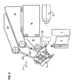
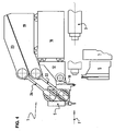
- the invention relates to a device for moving at least one tool holder assembly on a machine tool.
- the use of robotic arms for moving a tool holder on a machine tool is known: see for example DE3913655A1 .
- the invention also relates to the machine tool equipped with the aforementioned device for moving a tool holder assembly.
- One result that the invention aims to obtain is a device of the aforementioned type which, although it can be easily and quickly retracted from a first zone of a machine tool to a second zone of the machine tool and vice versa , can be placed in very precise positions with respect to a reference axis.
- the subject of the invention is a device according to claim 1.
- the first body consists of a tool 6 and the second body consists of a workpiece 2, but the first body may also consist of a workpiece 2 and the second body consist of a tool 6.
- n ' is not limiting the nature, nor the extent of the contact, nor the duration of this contact.
- It may be, for example, a touch probing contact, such a contact for a position reading, but it may also be a prolonged contact that changes the geometry of one of said first or second body, for example a contact causing a removal of material.
- the first body is a machining tool 5 and the second body is a workpiece 2, but this does not exclude the reciprocal, namely the first body is a workpiece 2 and the second body is a tool machining 5.
- the first device 3 is advantageously a pin which holds the first body, namely the workpiece 2, at a predetermined position with respect to at least one predetermined axis, called the reference axis 4, and in particular in a position aligned with said axis of rotation. reference 4.
- the machine tool 1 comprises two displacement devices 7 of the aforementioned type.
- the first determined distance is non-zero, i.e., has a value greater than zero.
- the device 7 located in the right part of the figure 5 is intended to work on a first body consisting of a workpiece 2 held by a pin 3 and the device located in the left part of the figure 5 is intended to work on another first body consisting of another workpiece 2 carried, for example, by a counter-spindle 30.
- first guide axis 110 is parallel to a first direction D1 which is in turn substantially perpendicular to the reference axis 4.
- the third element 16 is connected to the frame 100 of the machine tool 1 or at least part of this frame 100.
- third element 16 and the functional means 17, 18 makes it possible in particular to adjust the position of the tool-holder assembly 5 relative to the axis of reference 4 and according to a third guide axis 170 which is perpendicular to the reference axis 4.
- the presence of the third element 16 and the functional means 17, 18 associated therewith makes it possible in particular to adjust in height the position of the tool holder assembly 5 relative to the reference axis 4.
- the second determined distance is non-zero, i.e., has a value greater than zero.
- the first arm 22 is, by its so-called first end 221, articulated on the tool holder assembly 5 at the level of the first axis 110.
- the first end 221 of the first arm 22 is located above the level of the second end 222 of said first arm 22.
- the third end 261 of the second arm 26 is located above the level of the fourth end 262 of said second arm 26.
- the ninth functional means 27 controls the control of the fourth functional means 18, the sixth functional means 21, the eighth functional means 25 as a function of control commands that have been imposed on it.
- the ninth functional means 27 is part of the numerical control means (not shown) that the machine tool 1 comprises and this ninth functional means exploits pre-established command orders as a function of a workpiece profile 2.
- the elements and the functional means used to obtain the pivoting also have a function of adjusting the position along the guide axis.
- the device according to the invention is therefore economical in terms of functional means of controlled displacement.
- the first functional means for guiding rotation of the tool holder assembly 5 around the first guide axis 110 comprises a tenth functional means 28 for indicating the ninth functional means 27 of the angular position of the assembly. tool holder 5 around the first guide axis 110.
- second functional means for guiding rotation 13 of the first element 10 around the second guide axis 130 comprises an eleventh functional means 29 for indicating the ninth functional means 27 of the angular position of the first element 10 around the second axis of rotation. guidance 130.
Landscapes
- Engineering & Computer Science (AREA)
- Mechanical Engineering (AREA)
- Machine Tool Units (AREA)
- Automatic Tool Replacement In Machine Tools (AREA)
- Grinding And Polishing Of Tertiary Curved Surfaces And Surfaces With Complex Shapes (AREA)
Claims (16)
- Vorrichtung (7), um eine Werkzeughalteranordnung (5) zu bewegen zwischen:- einem ersten Bereich (8) einer Werkzeugmaschine (1), in der ein zweiter Körper, gehalten von der Werkzeughalteranordnung (5), mit einem ersten Körper in Kontakt treten kann, der hinsichtlich mindestens einer vorbestimmten Achse, genannt Bezugsachse (4), eine vorbestimmte Position einnimmt, und- einem zweiten Bereich (9) der Werkzeugmaschine (1), in den diese Werkzeughalteranordnung (5) vollständig eingezogen werden kann, um den ersten Bereich (8) freizugeben,wobei die Vorrichtung (7), um die Werkzeughalteranordnung (5) zu bewegen, Folgendes umfasst:- ein erstes Element (10), das die Werkzeughalteranordnung (5) über ein erstes funktionelles Mittel zum drehbaren Führen (11) um eine erste Führungsachse (110) hält, deren Ausrichtung und Position hinsichtlich der Bezugsachse vorbestimmt (4) sind,- ein zweites Element (12), das das erste Element (10) über ein zweites funktionelles Mittel zum drehbaren Führen (13) um eine zweite Führungsachse (130) hält, die im Wesentlichen parallel zur ersten Führungsachse (110) und von dieser durch einen ersten vorbestimmten Abstand (L1) getrennt ist,- für die Betätigung der Werkzeughalteranordnung (5) angesichts mindestens einer der Wirkungen, d.h. der Bewegung und der Positionierung der Werkzeughalteranordnung (5), ein drittes Element (16), das das zweite Element (12) durch ein drittes funktionelles Mittel (17) zum drehbaren Führen entlang einer dritten Führungsachse (170) hält, die im Wesentlichen parallel zur ersten Führungsachse (110) ist,- ein viertes funktionelles Mittel (18) zur gesteuerten drehbaren Bewegung entlang der dritten Führungsachse (170),- eine erste funktionelle Anordnung (14) zur gesteuerten Bewegung des ersten Elementes (10) um die zweite Führungsachse (130),- eine zweite funktionelle Anordnung (15) zur gesteuerten Bewegung der Werkzeughalteranordnung (5) um die erste Führungsachse (110),wobei die Vorrichtung (7), um die Werkzeughalteranordnung (5) zu bewegen, dadurch gekennzeichnet ist, dass die erste funktionelle Anordnung (14) zur gesteuerten Bewegung des ersten Elementes (10) um die zweite Führungsachse (130) Folgendes umfasst:- ein viertes Element (19), gehalten vom dritten Element (16),- ein fünftes funktionelles Mittel (20) zum drehbaren Führen entlang einer vierten Führungsachse (200), die im Wesentlichen parallel zur ersten Führungsachse (110) und in einem zweiten vorbestimmten Abstand (L2) von der Bezugsachse (4) angebracht ist,- ein sechstes funktionelles Mittel (21) zur gesteuerten drehbaren Bewegung entlang der vierten Führungsachse (200),- einen ersten Arm (22), umfassend zwei gegenüber liegende Enden (221), (222), davon einem ersten Ende (221), das mit dem vierten Element (19) beweglich verbunden ist, und einem zweiten Ende (222), das beweglich mit der Werkzeughalteranordnung (5) verbunden ist,so dass, wenn das vierte Element (19) hinsichtlich des ersten Elementes (10) drehbar bewegt wird, der erste Arm (22) die Werkzeughalteranordnung (5) betätigt und die Drehung dieser Werkzeughalteranordnung (5) um die erste Führungsachse (110) hervorruft.
- Vorrichtung nach Anspruch 1, dadurch gekennzeichnet, dass die erste Führungsachse (110) parallel zu einer ersten Richtung (D1) ist, die ihrerseits im Wesentlichen senkrecht zur Bezugsachse (4) ist.
- Vorrichtung nach Anspruch 1, dadurch gekennzeichnet, dass der erste Arm (22) durch sein Ende, genannt erstes Ende (221), mit der Werkzeughalteranordnung (5) auf der Ebene der ersten Achse (110) beweglich verbunden ist.
- Vorrichtung nach einem der Ansprüche 1 bis 3, dadurch gekennzeichnet, dass, hinsichtlich einer Ebene, genannt Bezugsebene, die als im Wesentlichen horizontal erachtet wird, einerseits umfassend die Bezugsachse (4) und zu der, andererseits, die erste Führungsachse (110) rechtwinklig ist, das erste Ende (221) des ersten Arms (22) über der Ebene des zweiten Endes (222) des ersten Arms (22) angeordnet ist.
- Vorrichtung nach einem der Ansprüche 1 bis 4, dadurch gekennzeichnet, dass, die zweite funktionelle Anordnung (15) zur gesteuerten Bewegung der Werkzeughalteranordnung (5) um die erste Führungsachse (110) Folgendes umfasst:- ein fünftes Element (23), gehalten vom vierten Element (19) durch,. ein siebtes funktionelles Mittel (24) zum drehbaren Führen entlang einer fünften Führungsachse (240), die, in Projektion auf eine Ebene, genannt Bezugsebene, einerseits umfassend die Bezugsachse (4) und zu der, andererseits, die erste Führungsachse (110) rechtwinklig ist, zu dieser Bezugsachse (4) schneidend ist,. ein achtes funktionelles Mittel (25) zur gesteuerten drehbaren Bewegung entlang der fünften Führungsachse (250),- ein zweiter Arm (26), umfassend zwei gegenüber liegende Enden, davon ein drittes Ende (261), das beweglich mit dem fünften Element (23) verbunden ist, und ein viertes Ende (262), das beweglich mit der Werkzeughalteranordnung (5) verbunden ist,so dass, wenn das fünfte Element (23) hinsichtlich des ersten Elementes (10) drehbar bewegt wird, der zweite Arm (26) die Werkzeughalteranordnung (5) betätigt und die Drehung dieser Werkzeughalteranordnung (5) um die erste Drehachse (110) erzeugt.
- Vorrichtung nach Anspruch 5, dadurch gekennzeichnet, dass, hinsichtlich einer Ebene, genannt Bezugsebene, die als im Wesentlichen horizontal erachtet wird, einerseits umfassend die Bezugsachse (4) und zu der, andererseits, die erste Führungsachse (110) rechtwinklig ist, das dritte Ende (261) des zweiten Arms (26) über der Ebene des vierten Endes (262) des zweiten Arms (26) angeordnet ist.
- Vorrichtung nach einem der Ansprüche 5 oder 6, dadurch gekennzeichnet, dass sie ein neuntes funktionelles Mittel (27) umfasst, um die Steuerung zu verwalten,. des vierten funktionellen Mittels (18) zur gesteuerten drehbaren Bewegung entlang der dritten Führungsachse (170), und. des sechsten funktionellen Mittels (21) zur gesteuerten drehbaren Bewegung entlang der vierten Führungsachse (200), und. des achten funktionellen Mittels (25) zur gesteuerten drehbaren Bewegung entlang der fünften Führungsachse (250),so dass:- das vierte Mittel (18) verwendet wird, um die Höhe der Werkzeughalteranordnung (5) bezüglich der Bezugsachse (4) einzustellen, ohne, dass dies notwendigerweise zu mindestens einer der Drehungen führt, d.h.. einer Drehung der Werkzeughalteranordnung (5) entlang der ersten Führungsachse (110), und. einer Drehung des ersten Elements (10) entlang der zweiten Führungsachse (130), und- das sechste Mittel (21) verwendet wird, um die Position der Werkzeughalteranordnung entlang der ersten Achse (110) einzustellen, ohne, dass dies notwendigerweise zu mindestens einer der Drehungen führt, d.h.. einer Drehung der Werkzeughalteranordnung (5) entlang der ersten Führungsachse (110), und. einer Drehung des ersten Elements (10) entlang der zweiten Führungsachse (130), und- das achte funktionelle Mittel (25) verwendet wird, um die Position der Werkzeughalteranordnung (5) entlang der ersten Achse (100) einzustellen, ohne, dass dies notwendigerweise zu einer der Drehungen des ersten Elements (10) entlang der zweiten Führungsachse (130) führt.
- Vorrichtung nach einem der Ansprüche 1 bis 7, dadurch gekennzeichnet, dass das erste funktionelle Mittel zur drehbaren Führung (11) der Werkzeughalteranordnung (5) um die erste Führungsachse (110) ein zehntes funktionelles Mittel (28) zur Angabe der Winkelposition der Werkzeughalteranordnung (5) um die erste Führungsachse (110) an das neunte funktionelle Mittel (27) umfasst.
- Vorrichtung nach einem der Ansprüche 1 bis 8, dadurch gekennzeichnet, dass das zweite funktionelle Mittel zur drehbaren Führung (13) des ersten Elementes (10) um die zweite Führungsachse (130) ein elftes funktionelles Mittel (29) zur Angabe der Winkelposition des ersten Elements (10) um die zweite Führungsachse (130) an das neunte funktionelle Mittel (27) umfasst.
- Verfahren nach einem der Ansprüche 1 bis 9, dadurch gekennzeichnet, dass:- das erste Ende (221) des ersten Arms (22) mit dem vierten Element (19) durch ein erstes Verbindungsorgan (2210) des Typs Kugelgelenk beweglich verbunden ist,- das zweite Ende (222) des ersten Arms (22) mit der Werkzeughalteranordnung (5) durch ein zweites Verbindungsorgan (2220) des Typs Kugelgelenk beweglich verbunden ist.
- Verfahren nach einem der Ansprüche 5 bis 9, dadurch gekennzeichnet, dass:- das dritte Ende (261) des zweiten Arms (26) mit dem fünften Element (23) durch ein drittes Verbindungsorgan (2610) des Typs Kugelgelenk beweglich verbunden ist,- das vierte Ende (262) des zweiten Arms (26) mit der Werkzeughalteranordnung (5) durch ein viertes Verbindungsorgan (2620) des Typs Kugelgelenk beweglich verbunden ist.
- Vorrichtung nach einem der Ansprüche 1 bis 11, dadurch gekennzeichnet, dass der erste Körper ein Werkzeug (6) umfasst und der zweite Körper ein Werkstück (2) umfasst.
- Vorrichtung nach einem der Ansprüche 1 bis 11, dadurch gekennzeichnet, dass der erste Körper ein Werkstück (2) umfasst und der zweite Körper ein Werkzeug (6) umfasst.
- Vorrichtung nach einem der Ansprüche 1 bis 11, dadurch gekennzeichnet, dass der erste Körper ein Werkzeug (6) umfasst und der zweite Körper ebenfalls ein Werkzeug (6) umfasst.
- Vorrichtung nach einem der Ansprüche 1 bis 11, dadurch gekennzeichnet, dass der erste Körper ein Werkstück (2) umfasst und der zweite Körper ebenfalls ein Werkzeug (2) umfasst.
- Werkzeugmaschine, dadurch gekennzeichnet, dass sie mit mindestens einer Vorrichtung nach einem der Ansprüche 1 bis 15 ausgestattet ist.
Priority Applications (3)
| Application Number | Priority Date | Filing Date | Title |
|---|---|---|---|
| EP05112580A EP1800794B1 (de) | 2005-12-21 | 2005-12-21 | Vorrichtung zum Verschieben eines Werkzeugträgers |
| AT05112580T ATE425839T1 (de) | 2005-12-21 | 2005-12-21 | Vorrichtung zum verschieben eines werkzeugtragers |
| DE602005013413T DE602005013413D1 (de) | 2005-12-21 | 2005-12-21 | Vorrichtung zum Verschieben eines Werkzeugträgers |
Applications Claiming Priority (1)
| Application Number | Priority Date | Filing Date | Title |
|---|---|---|---|
| EP05112580A EP1800794B1 (de) | 2005-12-21 | 2005-12-21 | Vorrichtung zum Verschieben eines Werkzeugträgers |
Publications (2)
| Publication Number | Publication Date |
|---|---|
| EP1800794A1 EP1800794A1 (de) | 2007-06-27 |
| EP1800794B1 true EP1800794B1 (de) | 2009-03-18 |
Family
ID=36499683
Family Applications (1)
| Application Number | Title | Priority Date | Filing Date |
|---|---|---|---|
| EP05112580A Ceased EP1800794B1 (de) | 2005-12-21 | 2005-12-21 | Vorrichtung zum Verschieben eines Werkzeugträgers |
Country Status (3)
| Country | Link |
|---|---|
| EP (1) | EP1800794B1 (de) |
| AT (1) | ATE425839T1 (de) |
| DE (1) | DE602005013413D1 (de) |
Family Cites Families (2)
| Publication number | Priority date | Publication date | Assignee | Title |
|---|---|---|---|---|
| DE3913655A1 (de) * | 1989-04-26 | 1990-10-31 | Frech Oskar Gmbh & Co | Knickarm-schwenkeinrichtung eines industrieroboters |
| AU3447699A (en) * | 1998-08-19 | 2000-03-14 | Kenan Koser | Closed kinematic chain robot arm |
-
2005
- 2005-12-21 EP EP05112580A patent/EP1800794B1/de not_active Ceased
- 2005-12-21 DE DE602005013413T patent/DE602005013413D1/de not_active Expired - Lifetime
- 2005-12-21 AT AT05112580T patent/ATE425839T1/de not_active IP Right Cessation
Also Published As
| Publication number | Publication date |
|---|---|
| EP1800794A1 (de) | 2007-06-27 |
| DE602005013413D1 (de) | 2009-04-30 |
| ATE425839T1 (de) | 2009-04-15 |
Similar Documents
| Publication | Publication Date | Title |
|---|---|---|
| FR2989010A3 (fr) | Scie a onglet | |
| FR2609660A1 (fr) | Machine a meuler, notamment pour meuler des branches de ciseaux | |
| EP0245177A1 (de) | Vorrichtung zum Stützen eines Werkstückes zur Ermöglichung der Bearbeitung auf seiner fünften Fläche | |
| FR2876611A1 (fr) | Dispositif de coupe et de marquage d'un cable metallique | |
| EP1800794A1 (de) | Vorrichtung zum Verschieben eines Werkzeugträgers | |
| US3864828A (en) | Cable scribing tool | |
| EP0064069B1 (de) | Einrichtung zum orientieren eines führungskopfes einer funkenerosionsschneidemaschine | |
| FR2657035A1 (fr) | Machine pour l'affutage de forets helicouidaux. | |
| JP6871822B2 (ja) | 工具ホルダ及びタップオイル供給ユニット | |
| US1031318A (en) | Cutter for forming irregular surfaces. | |
| EP1726389B1 (de) | Werkzeugmaschine mit mobiler Führungsbuchse für die Herstellung von Teilen durch Abstechen | |
| EP1125687A1 (de) | Mutter zum Spannen und Sichern eines Werkzeuges, sowie eine Scheibe auf der Spindel einer Bearbeitungsmaschine | |
| CH628828A5 (en) | Device for actuating a chuck in the headstock of a lathe | |
| WO1995026853A1 (fr) | Support de torche a plasma pour machine de decoupe d'une tole | |
| CH225012A (fr) | Machine-outil. | |
| FR2776551A1 (fr) | Dispositif de correction angulaire pour dispositif de pilotage a distance de mouvement | |
| US410901A (en) | Center-rest for lathes | |
| EP3173185B1 (de) | Werkzeugmaschine | |
| US990787A (en) | Cutting-tool. | |
| JP2000263544A (ja) | ガラス板切削具 | |
| FR2466288A1 (fr) | Machine pour la realisation de piquages et de calibrages sur les tubes | |
| EP0085613A2 (de) | Spannvorrichtung für ein Werkstück | |
| BE488623A (de) | ||
| EP1555086A1 (de) | Werkzeugmaschine mit radial angeordneten Werkzeugen | |
| FR2598640A1 (fr) | Procede et machine de rivetage |
Legal Events
| Date | Code | Title | Description |
|---|---|---|---|
| PUAI | Public reference made under article 153(3) epc to a published international application that has entered the european phase |
Free format text: ORIGINAL CODE: 0009012 |
|
| AK | Designated contracting states |
Kind code of ref document: A1 Designated state(s): AT BE BG CH CY CZ DE DK EE ES FI FR GB GR HU IE IS IT LI LT LU LV MC NL PL PT RO SE SI SK TR |
|
| AX | Request for extension of the european patent |
Extension state: AL BA HR MK YU |
|
| 17P | Request for examination filed |
Effective date: 20071221 |
|
| 17Q | First examination report despatched |
Effective date: 20080125 |
|
| AKX | Designation fees paid |
Designated state(s): AT CH CZ DE GB LI |
|
| GRAP | Despatch of communication of intention to grant a patent |
Free format text: ORIGINAL CODE: EPIDOSNIGR1 |
|
| GRAS | Grant fee paid |
Free format text: ORIGINAL CODE: EPIDOSNIGR3 |
|
| GRAA | (expected) grant |
Free format text: ORIGINAL CODE: 0009210 |
|
| AK | Designated contracting states |
Kind code of ref document: B1 Designated state(s): AT CH CZ DE GB LI |
|
| REG | Reference to a national code |
Ref country code: GB Ref legal event code: FG4D Free format text: NOT ENGLISH |
|
| REG | Reference to a national code |
Ref country code: CH Ref legal event code: EP |
|
| REF | Corresponds to: |
Ref document number: 602005013413 Country of ref document: DE Date of ref document: 20090430 Kind code of ref document: P |
|
| REG | Reference to a national code |
Ref country code: CH Ref legal event code: NV Representative=s name: BOVARD AG PATENTANWAELTE |
|
| PLBE | No opposition filed within time limit |
Free format text: ORIGINAL CODE: 0009261 |
|
| STAA | Information on the status of an ep patent application or granted ep patent |
Free format text: STATUS: NO OPPOSITION FILED WITHIN TIME LIMIT |
|
| 26N | No opposition filed |
Effective date: 20091221 |
|
| PGFP | Annual fee paid to national office [announced via postgrant information from national office to epo] |
Ref country code: GB Payment date: 20101221 Year of fee payment: 6 |
|
| REG | Reference to a national code |
Ref country code: CH Ref legal event code: PFA Owner name: TORNOS SA Free format text: TORNOS SA#RUE INDUSTRIELLE 111#2740 MOUTIER (CH) -TRANSFER TO- TORNOS SA#RUE INDUSTRIELLE 111#2740 MOUTIER (CH) |
|
| PG25 | Lapsed in a contracting state [announced via postgrant information from national office to epo] |
Ref country code: AT Free format text: LAPSE BECAUSE OF NON-PAYMENT OF DUE FEES Effective date: 20091221 |
|
| PGFP | Annual fee paid to national office [announced via postgrant information from national office to epo] |
Ref country code: CZ Payment date: 20111215 Year of fee payment: 7 |
|
| PG25 | Lapsed in a contracting state [announced via postgrant information from national office to epo] |
Ref country code: CZ Free format text: LAPSE BECAUSE OF NON-PAYMENT OF DUE FEES Effective date: 20121221 |
|
| GBPC | Gb: european patent ceased through non-payment of renewal fee |
Effective date: 20121221 |
|
| PG25 | Lapsed in a contracting state [announced via postgrant information from national office to epo] |
Ref country code: GB Free format text: LAPSE BECAUSE OF NON-PAYMENT OF DUE FEES Effective date: 20121221 |
|
| PGFP | Annual fee paid to national office [announced via postgrant information from national office to epo] |
Ref country code: CH Payment date: 20141204 Year of fee payment: 10 |
|
| REG | Reference to a national code |
Ref country code: CH Ref legal event code: PL |
|
| PG25 | Lapsed in a contracting state [announced via postgrant information from national office to epo] |
Ref country code: CH Free format text: LAPSE BECAUSE OF NON-PAYMENT OF DUE FEES Effective date: 20151231 Ref country code: LI Free format text: LAPSE BECAUSE OF NON-PAYMENT OF DUE FEES Effective date: 20151231 |
|
| P01 | Opt-out of the competence of the unified patent court (upc) registered |
Effective date: 20230630 |
|
| PGFP | Annual fee paid to national office [announced via postgrant information from national office to epo] |
Ref country code: DE Payment date: 20231214 Year of fee payment: 19 |
|
| REG | Reference to a national code |
Ref country code: DE Ref legal event code: R119 Ref document number: 602005013413 Country of ref document: DE |
|
| PG25 | Lapsed in a contracting state [announced via postgrant information from national office to epo] |
Ref country code: DE Free format text: LAPSE BECAUSE OF NON-PAYMENT OF DUE FEES Effective date: 20250701 |