EP1800938B1 - Halterung für eine Sitzgurteinzugseinheit - Google Patents
Halterung für eine Sitzgurteinzugseinheit Download PDFInfo
- Publication number
- EP1800938B1 EP1800938B1 EP06125533A EP06125533A EP1800938B1 EP 1800938 B1 EP1800938 B1 EP 1800938B1 EP 06125533 A EP06125533 A EP 06125533A EP 06125533 A EP06125533 A EP 06125533A EP 1800938 B1 EP1800938 B1 EP 1800938B1
- Authority
- EP
- European Patent Office
- Prior art keywords
- seat belt
- mounting
- vehicle
- seat
- top tether
- Prior art date
- Legal status (The legal status is an assumption and is not a legal conclusion. Google has not performed a legal analysis and makes no representation as to the accuracy of the status listed.)
- Active
Links
- 230000002787 reinforcement Effects 0.000 description 20
- 229910000831 Steel Inorganic materials 0.000 description 5
- 239000000463 material Substances 0.000 description 5
- 239000010959 steel Substances 0.000 description 5
- -1 for example Substances 0.000 description 4
- 238000009434 installation Methods 0.000 description 4
- 238000004873 anchoring Methods 0.000 description 2
- 231100001261 hazardous Toxicity 0.000 description 2
- 238000010276 construction Methods 0.000 description 1
- 230000001419 dependent effect Effects 0.000 description 1
- 230000000694 effects Effects 0.000 description 1
- 239000011521 glass Substances 0.000 description 1
- 238000004519 manufacturing process Methods 0.000 description 1
- 238000003466 welding Methods 0.000 description 1
Images


Classifications
-
- B—PERFORMING OPERATIONS; TRANSPORTING
- B60—VEHICLES IN GENERAL
- B60R—VEHICLES, VEHICLE FITTINGS, OR VEHICLE PARTS, NOT OTHERWISE PROVIDED FOR
- B60R22/00—Safety belts or body harnesses in vehicles
- B60R22/18—Anchoring devices
- B60R22/24—Anchoring devices secured to the side, door, or roof of the vehicle
-
- B—PERFORMING OPERATIONS; TRANSPORTING
- B60—VEHICLES IN GENERAL
- B60R—VEHICLES, VEHICLE FITTINGS, OR VEHICLE PARTS, NOT OTHERWISE PROVIDED FOR
- B60R22/00—Safety belts or body harnesses in vehicles
- B60R22/34—Belt retractors, e.g. reels
- B60R22/46—Reels with means to tension the belt in an emergency by forced winding up
- B60R22/4604—Reels with means to tension the belt in an emergency by forced winding up characterised by arrangements in vehicle or relative to seat belt
-
- B—PERFORMING OPERATIONS; TRANSPORTING
- B60—VEHICLES IN GENERAL
- B60R—VEHICLES, VEHICLE FITTINGS, OR VEHICLE PARTS, NOT OTHERWISE PROVIDED FOR
- B60R22/00—Safety belts or body harnesses in vehicles
- B60R22/10—Safety belts or body harnesses in vehicles specially adapted for children or animals
- B60R22/105—Safety belts or body harnesses in vehicles specially adapted for children or animals for children
Definitions
- the present invention relates to a mounting for a roof mounted seat belt retractor unit.
- Child seats and especially those for younger children, comprise a moulded seat having a booster portion and a back portion configured to the requirements of average children between certain ages.
- Seats of this type are generally secured in position by means of a conventional seat belt, which is threaded through anchorage portions provided in the seat back, as illustrated in Figure 3 .
- the car seat is provided with mechanical latches arranged for interconnection with corresponding brackets mounted to the vehicle body or seat.
- US 2 852 270 discloses a seat belt apparatus for a vehicle comprising a flexible belt with a bayonet-type fastener means attached to one end of the belt and a retractor onto which the belt is wound mounted to the vehicle seat.
- a receptacle type receiving means is provided on the vehicle door behind a cover plate and is arranged to engage with the fastener means using spring-loaded jaws.
- a known issue associated with such car seats is their tendency to pitch forward in the event of a frontal impact to a vehicle in which they are secured. Such movement represents a significant hazard not only to a child secured in the child seat, but also to a front seat passenger, or driver sitting in front of the child seat.
- top tether comprising a strip of suitably robust material which, in operation, extends from an upper portion of the child seat to a top tether anchor located at a suitable location within the vehicle.
- the top tether anchor has to be sufficiently robust to withstand the load exerted by the combined weight of the child and child seat during a typical impact, as specified in appropriate standards and/or legislation.
- the top tether anchor has to be mounted in a correspondingly robust location within the vehicle.
- top tether anchor is sometimes mounted on the back of a rear seat of the vehicle.
- a position is difficult to access, thereby making installation of the associated car seat time consuming and prone to potentially hazardous error.
- the risk of incorrect installation is increased because top tethers secured vi a anchors mounted on the back of the rear seat are difficult to tension sufficiently.
- location of the anchor on the back of the rear seat can lead to potentially hazardous rear seat deformation during severe impacts.
- the top tether anchor is sometimes mounted to a floor or rear panel of a rear luggage area of the vehicle.
- this location also has access difficulties, and results in a significant reduction in luggage area capacity when a correctly tensioned top tether strap extends across the space.
- items placed in the luggage area can potentially impinge on the strap during impact, resulting in unpredictable effects, and in extreme cases the severing of the tether during impact.
- the present invention provides an improved mounting which significantly mitigates at least some of the above problems.
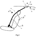
- FIGS 1 and 2 show a roof-mounted rear seat belt assembly generally at 10.
- the seat belt assembly comprises a belt portion 12, and a mounting portion 14.
- the roof-mounted rear seat belt assembly is provided for a central rear seat 16 of a hatchback vehicle 18. It will be appreciated however, that roof-mounted seat belts may alternatively or additionally be provided for any occupant of any suitable vehicle.
- the mounting portion 14 comprises means for mounting a seat belt retractor unit internally to a reinforced section 20 of the roof 22 of the vehicle 18.
- the mounting portion 14 is located on the roof 22 of the vehicle 18 between a rear seat and the back of the vehicle.
- the seat belt 12 is extendable from and retractable into the retractor unit, in operation, to allow a user to adjust the seat belt 12 to a desired length.
- the mounting may alternatively or additionally comprise roof mounting means for a seat belt assembly of any suitable type, for example an assembly having a roof mounted 'D' loop through which the belt is routed, as opposed to the retractor unit.
- the mounting portion is required to be of sufficient robustness to withstand the load exerted by an adult during a frontal impact to the vehicle 18 as defined by relevant standards and/or legislation.
- the retractor unit 14 includes means for arresting deceleration induced momentum of a wearer during heavy braking or an impact caused by an accident.
- Seat belt mountings comprising retractor units having impact arrest means are extremely well known i n the art and will not be described again in detail.
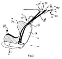
- Figure 3 shows a roof-mounted seat belt assembly similar to that of Figures 1 and 2 , and like parts are given like reference numerals.
- the assembly of Figure 3 includes a mounting portion 14' according to the invention.
- a child seat is shown generally at 30, in position secured to a rear seat 60 of a vehicle by a roof-mounted seat belt 12.
- the child seat 30 comprises a moulded seat having a booster portion 32 and a back portion 34 configured to the requirements of an average child of a particular age.
- the child seat is provided with a top tether 36 for improved impact stability, which extends from an upper portion of the child seat back portion 34.
- the mounting portion 14' comprises a seat belt retractor unit mounted to a reinforced portion 20 of a roof 22 of the vehicle, as generally described previously. However, the mounting portion 14' is further provided with means 38 for anchoring the top tether 36, with sufficient tension substantially to prevent the child seat 30 from pitching forward during a frontal impact, heavy braking or similar.
- the top tether anchoring means 38 comprises an anchorage portion suitable for engagement with the top tether 36 to robustly secure the tether 36 at the desired tension.
- the top tether anchorage portion 38 comprises a "D" loop, a self-locking or open hook, or a downwardly extending anchorage portion having an aperture of suitable shape and dimensions for engagement with a corresponding portion of the tether 36.
- the mounting portion 14' is provided with a hinged cover portion for concealing the top tether anchorage portion 38 when not in use.
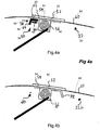
- FIGS. 4a to 4d show four possible embodiments of a mounting portion according to the invention in more detail.
- FIG 4a a cross-section of a first embodiment of a mounting portion is shown generally at 50.
- the mounting portion 50 comprises a reinforcement portion 52, a base plate 54, a seat belt retractor unit 56, and a top tether anchor 58.
- the reinforcement portion 52 comprises reinforcement located within the roof 22 of the vehicle between an internal roof layer 60 and an external roof layer (not shown).
- the reinforcement portion 52 may comprise any suitable reinforcement but typically comprises a steel plate, or the like, robustly secured to a reinforced body shell of the vehicle 18.
- the base plate 54 is secured to the reinforcement portion 52 using appropriate means (not shown), for example, bolts, rivets, welding or the like.
- the seat belt retractor unit 56 comprises means for allowing the extension and retraction of a seat belt and means for arresting deceleration induced momentum of a wearer as generally described previously.
- the retractor unit is integral with the base plate 54 although it will be appreciated that alternatively the retractor unit may be fixed to the base plate using appropriate means, for example, bolts, rivets, or the like.
- the reinforcement 52, base plate 54, and retractor 56 are configured such that when the base plate 54 is secured to the reinforcement portion 52 the mounting has sufficient structural integrity to withstand the load exerted by an adult wearer of the belt, during a frontal impact to the vehicle 18 as defined by relevant standards and/or legislation.
- the top tether anchor 58 comprises a generally planar fixing portion 62, and a tether engagement portion 64 extending at an angle from the plane of the fixing portion 62.
- the fixing portion 62 is configured for robust mounting to the base plate 54, in operation, using suitable means 66, for example, bolts, rivets, or the like.
- the engagement portion 64 is configured to extend at an angle downwardly from the mounting 50 when the engagement portion is secured to the base plate 54, in operation.
- the fixing and engagement portions 62, 64 may be formed from a single section of robust material, for example, steel or the like.
- the engagement portion 64 is provided with an aperture (not shown) configured for engagement with a securing portion of a top tether, such as a self-locking hook or the like. It will be appreciated that alternatively, or additionally, the engagement portion may be provided with alternative fixing means, for example, a "D" loop, a self-locking or open hook, or the like.
- the top tether anchor 58 is required, in operation, to withstand the load exerted by the combined weight of the child and child seat during a typical impact or heavy braking. Hence, the load endurance requirement of the top tether anchor 58 is significantly less than the load endurance required by the mounting portion. Thus, the load endurance requirements of the top tether anchor are inherently met by the construction of the mounting portion 50. Hence, in operation to secure a car seat having a top tether to a vehicle seat having a roof mounted safety belt assembly, a user may connect the top tether to the engagement portion 64 of the anchor 58, and tension the tether appropriately.
- the position of the mounting portion 50 provides more convenient access than known locations for top tether anchorage, does not impinge on luggage space, and provides a robust location for top tether anchorage without significant additional vehicle development and/or manufacture costs.
- FIG 4b a cross-section of a second embodiment of a mounting portion is shown generally as 70.
- the mounting portion 70 comprises a reinforcement portion 52, a base plate 54, a seat belt retractor unit 56, as generally described previously with reference to figure 4a and like features are given like reference numerals.
- the mounting portion 70 also includes a top tether anchor 72.
- the anchor 72 of the second embodiment is provided integrally with the base plate 54.
- the top tether anchor 72 comprises a tether engagement portion, which extends at an angle downwardly from the base plate 54, when the base plate 54 is secured to the reinforcement portion, in operation.
- the base plate 54 and engagement portion 72 may be formed from a single section of robust material, for example, steel or the like.
- the engagement portion 72 is provided with an aperture (not shown) configured for engagement with a securing portion of a top tether, such as a self-locking hook or the like. It will be appreciated that alternatively, or additionally, the engagement porti on may be provided with alternative fixing means, for example, a "D" loop, a self-locking or open hook, or the like.
- FIG 4c a cross-section of a third embodiment of a mounting portion is shown generally at 80.
- the mounting portion 80 comprises a reinforcement portion 52, a base plate 54, a seat belt retractor unit 56, as generally described previously with reference to figure 4a and like features are given like reference numerals.
- the mounting portion 80 also includes a top tether anchor 82.
- the anchor 82 of the third embodiment is provided integrally with the reinforcement portion 52.
- the top tether anchor 82 comprises a tether engagement porti on, which extends at an angle downwardly from the reinforcement portion 52.
- the reinforcement portion 52 and engagement portion 82 may be formed from a single section of robust material, for example, steel or the like.
- the engagement portion 82 is provided with an aperture (not shown) configured for engagement with a securing portion of a top tether, such as a self-locking hook or the like.
- a securing portion of a top tether such as a self-locking hook or the like.
- the engagement porti on maybe provided with alternative fixing means, for example, a "D" loop, a self-locking or open hook, or the like.
- FIG 4d a cross-section of a fourth embodiment of a mounting portion is shown generally at 90.
- the mounting portion 90 comprises a reinforcement portion 52, a base plate 54, a seat belt retractor unit 56, as generally described previously with reference to figure 4a and like features are given like reference numerals.
- the mounting portion 90 also includes a top tether anchor 92 comprising a generally planar fixing portion 62, and a tether engagement porti on 64 extending at an angle from the plane of the fixing portion 62 as generally described previously.
- the fixing portion 62 is configured for robust mounting to the reinforcement portion 52, in operation, using suitable means 66, for example, bolts, rivets, or the like.
- the engagement portion 64 is configured to extend at an angle downwardly from the mounting 50 when the engagement portion is secured to the reinforcement portion 52, in operation.
- the fixing and engagement portions 62, 64 may be formed from a single section of robust material, for example, steel or the like.
- the engagement portion 92 is provided with an aperture (not shown) configured for engagement with a securing portion of a top tether, such as a self-locking hook or the like. It will be appreciated that alternatively, or additionally, the engagement portion may be provided with alternative fixing means, for example, a "D" loop, a self-locking or open hook, or the like.
Landscapes
- Engineering & Computer Science (AREA)
- Mechanical Engineering (AREA)
- Automotive Seat Belt Assembly (AREA)
Claims (7)
- Sicherheitsgurt-Baugruppe für ein Fahrzeug, die Folgendes umfasst:eine Sicherheitsgurt-Einzugseinheit (56); undeine Halterung (14', 50, 70, 80, 90), die eine Grundplatte (54) zum Anbringen der Sicherheitsgurt-Einzugseinheit (56) am Dach des Fahrzeugs (22) umfasst;dadurch gekennzeichnet, dass die Halterung (14', 50, 70, 80, 90) einen Eingriffsabschnitt (64, 72, 82) für einen oberen Haltegurt umfasst, der dazu angeordnet ist, mit einer Verankerung (36) eines oberen Haltegurts eines Kindersitzes (30) in Eingriff zu treten, so dass die Verankerung des oberen Haltegurts an der Halterung (14', 50, 70, 80, 90) befestigt ist.
- Sicherheitsgurt-Baugruppe nach Anspruch 1, wobei die genannte Grundplatte (54) für die starre Verbindung mit einem verstärkten Abschnitt (52) im Dach des Fahrzeugs zwischen einem Sitz des genannten Fahrzeugs und dem Heck des genannten Fahrzeugs ausgebildet ist.
- Sicherheitsgurt-Baugruppe nach Anspruch 1 oder Anspruch 2, wobei der Eingriffsabschnitt (72) für den oberen Haltegurt mit der genannten Grundplatte (54) integriert ist.
- Sicherheitsgurt-Baugruppe nach Anspruch 1 oder Anspruch 2, wobei der Eingriffsabschnitt (64) für den oberen Haltegurt unter Verwendung von Befestigungsmitteln starr an der genannten Grundplatte (54) angebracht ist.
- Sicherheitsgurt-Baugruppe nach Anspruch 1 oder Anspruch 2, wobei der Eingriffsabschnitt (82) für den oberen Haltegurt mit dem genannten verstärkten Abschnitt des genannten Fahrzeugs integriert ist.
- Sicherheitsgurt-Baugruppe nach einem der Ansprüche 1 bis 5, wobei die genannte Grundplatte (54) mit der genannten Sicherheitsgurt-Einzugseinheit (56) integriert ist.
- Fahrzeug, das eine Halterung nach einem der vorangehenden Ansprüche umfasst.
Applications Claiming Priority (1)
| Application Number | Priority Date | Filing Date | Title |
|---|---|---|---|
| GB0526112A GB2433476A (en) | 2005-12-22 | 2005-12-22 | Roof mounted anchorage for child seat |
Publications (3)
| Publication Number | Publication Date |
|---|---|
| EP1800938A1 EP1800938A1 (de) | 2007-06-27 |
| EP1800938B1 true EP1800938B1 (de) | 2009-05-20 |
| EP1800938B9 EP1800938B9 (de) | 2010-09-15 |
Family
ID=35840958
Family Applications (1)
| Application Number | Title | Priority Date | Filing Date |
|---|---|---|---|
| EP06125533A Active EP1800938B9 (de) | 2005-12-22 | 2006-12-06 | Halterung für eine Sitzgurteinzugseinheit |
Country Status (3)
| Country | Link |
|---|---|
| EP (1) | EP1800938B9 (de) |
| DE (1) | DE602006006895D1 (de) |
| GB (1) | GB2433476A (de) |
Families Citing this family (3)
| Publication number | Priority date | Publication date | Assignee | Title |
|---|---|---|---|---|
| JP6240054B2 (ja) * | 2014-10-17 | 2017-11-29 | 本田技研工業株式会社 | 車両 |
| CN106740306A (zh) * | 2016-11-30 | 2017-05-31 | 好孩子儿童用品有限公司 | 一种儿童汽车安全座椅 |
| US10632962B2 (en) * | 2017-11-30 | 2020-04-28 | Ford Global Technologies, Llc | Seatbelt retractor |
Family Cites Families (11)
| Publication number | Priority date | Publication date | Assignee | Title |
|---|---|---|---|---|
| US2852270A (en) | 1956-01-03 | 1958-09-16 | Hunt Russell Garnsey | Safety belt apparatus for vehicles |
| US3534979A (en) * | 1969-05-08 | 1970-10-20 | American Seating Co | Safety vehicle |
| JPS5934958A (ja) * | 1982-08-23 | 1984-02-25 | Nissan Shatai Co Ltd | シ−トベルト装置 |
| FR2671317A1 (fr) * | 1991-01-04 | 1992-07-10 | Renault | Ceinture de securite pour siege de vehicule automobile. |
| US5176402A (en) * | 1991-08-21 | 1993-01-05 | Indiana Mills & Manufacturing, Inc. | Detachable vehicle belt guide |
| FR2681564B1 (fr) * | 1991-09-24 | 1993-11-26 | Renault Regie Nale Usines | Ceinture de securite pour siege de vehicule automobile. |
| GB2357469B (en) * | 1999-12-23 | 2002-10-09 | Breed Automotive Tech | Vehicle safety restraint |
| US6334628B1 (en) * | 2000-04-28 | 2002-01-01 | Honda Giken Kogyo Kabushiki Kaisha | Ceiling retractable three point seat belt system |
| GB0113280D0 (en) * | 2001-06-01 | 2001-07-25 | Britax Roemer Kindersicherheit Gmbh | Connector for safety seat |
| JP3846709B2 (ja) * | 2002-03-18 | 2006-11-15 | スズキ株式会社 | シートベルト装置におけるシートベルト連結具の収納構造 |
| DE20317226U1 (de) * | 2003-08-02 | 2004-01-22 | Opel Eisenach Gmbh | Vorrichtung zur Ablage der beiden lösbaren Schlosszungen eines Dreipunkt-Sicherheitsgurtsystems für Fahrzeuge, insbesondere Kraftfahrzeuge |
-
2005
- 2005-12-22 GB GB0526112A patent/GB2433476A/en not_active Withdrawn
-
2006
- 2006-12-06 DE DE602006006895T patent/DE602006006895D1/de active Active
- 2006-12-06 EP EP06125533A patent/EP1800938B9/de active Active
Also Published As
| Publication number | Publication date |
|---|---|
| GB2433476A (en) | 2007-06-27 |
| EP1800938B9 (de) | 2010-09-15 |
| EP1800938A1 (de) | 2007-06-27 |
| DE602006006895D1 (de) | 2009-07-02 |
| GB0526112D0 (en) | 2006-02-01 |
Similar Documents
| Publication | Publication Date | Title |
|---|---|---|
| US7896434B2 (en) | Seat assembly for a vehicle | |
| US6460912B2 (en) | Load restraining vehicular barrier device | |
| US20020190513A1 (en) | Automotive safety net system | |
| JPH10504506A (ja) | 荷物安全障壁 | |
| WO2004069594A2 (en) | Seat belt restraint system with double shoulder belts | |
| US6666520B2 (en) | Occupant restraint system and kit with compartmentalization | |
| GB2444592A (en) | Energy absorbing anchor for child safety seats | |
| JP3716400B2 (ja) | リヤシート用シートベルト装置の取付構造 | |
| US5590907A (en) | Seat belt positioning device and system | |
| CA2343955A1 (en) | Child restraint system | |
| US7380853B2 (en) | Crash appropriate vehicle partition | |
| GB2287645A (en) | Dual vehicle seat with belt attachment beam | |
| EP1800938B9 (de) | Halterung für eine Sitzgurteinzugseinheit | |
| JPH0995196A (ja) | 乗員保護装置 | |
| US20050189802A1 (en) | School bus occupant restraint passenger seat | |
| AU667273B2 (en) | An improved motor vehicle safety screen assembly | |
| KR100435387B1 (ko) | 자동차용 시트의 슬라이드 트랙 좌굴 방지 구조 | |
| JPH0225722Y2 (de) | ||
| JP4407683B2 (ja) | シートベルト装置 | |
| KR0123274Y1 (ko) | 자동차용 안전벨트의 앵커취부구조 | |
| JPH042110Y2 (de) | ||
| KR970006226Y1 (ko) | 차량용 좌석벨트의 장착구조 | |
| KR100279574B1 (ko) | 자동차필러의내장재구조 | |
| KR20150034869A (ko) | 리어시트의 안전벨트 | |
| JP2008100625A (ja) | シートベルトのアンカー構造 |
Legal Events
| Date | Code | Title | Description |
|---|---|---|---|
| PUAI | Public reference made under article 153(3) epc to a published international application that has entered the european phase |
Free format text: ORIGINAL CODE: 0009012 |
|
| AK | Designated contracting states |
Kind code of ref document: A1 Designated state(s): AT BE BG CH CY CZ DE DK EE ES FI FR GB GR HU IE IS IT LI LT LU LV MC NL PL PT RO SE SI SK TR |
|
| AX | Request for extension of the european patent |
Extension state: AL BA HR MK YU |
|
| 17P | Request for examination filed |
Effective date: 20071227 |
|
| 17Q | First examination report despatched |
Effective date: 20080201 |
|
| AKX | Designation fees paid |
Designated state(s): DE ES FR GB |
|
| RAX | Requested extension states of the european patent have changed |
Extension state: BA Payment date: 20071227 Extension state: HR Payment date: 20071227 Extension state: RS Payment date: 20071227 Extension state: MK Payment date: 20071227 Extension state: AL Payment date: 20071227 |
|
| GRAP | Despatch of communication of intention to grant a patent |
Free format text: ORIGINAL CODE: EPIDOSNIGR1 |
|
| GRAS | Grant fee paid |
Free format text: ORIGINAL CODE: EPIDOSNIGR3 |
|
| GRAA | (expected) grant |
Free format text: ORIGINAL CODE: 0009210 |
|
| AK | Designated contracting states |
Kind code of ref document: B1 Designated state(s): DE ES FR GB |
|
| AX | Request for extension of the european patent |
Extension state: AL BA HR MK RS |
|
| REG | Reference to a national code |
Ref country code: GB Ref legal event code: FG4D |
|
| REF | Corresponds to: |
Ref document number: 602006006895 Country of ref document: DE Date of ref document: 20090702 Kind code of ref document: P |
|
| PG25 | Lapsed in a contracting state [announced via postgrant information from national office to epo] |
Ref country code: ES Free format text: LAPSE BECAUSE OF FAILURE TO SUBMIT A TRANSLATION OF THE DESCRIPTION OR TO PAY THE FEE WITHIN THE PRESCRIBED TIME-LIMIT Effective date: 20090831 |
|
| PLBE | No opposition filed within time limit |
Free format text: ORIGINAL CODE: 0009261 |
|
| STAA | Information on the status of an ep patent application or granted ep patent |
Free format text: STATUS: NO OPPOSITION FILED WITHIN TIME LIMIT |
|
| 26N | No opposition filed |
Effective date: 20100223 |
|
| PGFP | Annual fee paid to national office [announced via postgrant information from national office to epo] |
Ref country code: DE Payment date: 20131218 Year of fee payment: 8 |
|
| PGFP | Annual fee paid to national office [announced via postgrant information from national office to epo] |
Ref country code: FR Payment date: 20131218 Year of fee payment: 8 |
|
| PGFP | Annual fee paid to national office [announced via postgrant information from national office to epo] |
Ref country code: GB Payment date: 20140130 Year of fee payment: 8 |
|
| REG | Reference to a national code |
Ref country code: DE Ref legal event code: R119 Ref document number: 602006006895 Country of ref document: DE |
|
| GBPC | Gb: european patent ceased through non-payment of renewal fee |
Effective date: 20141206 |
|
| REG | Reference to a national code |
Ref country code: FR Ref legal event code: ST Effective date: 20150831 |
|
| PG25 | Lapsed in a contracting state [announced via postgrant information from national office to epo] |
Ref country code: DE Free format text: LAPSE BECAUSE OF NON-PAYMENT OF DUE FEES Effective date: 20150701 Ref country code: GB Free format text: LAPSE BECAUSE OF NON-PAYMENT OF DUE FEES Effective date: 20141206 |
|
| PG25 | Lapsed in a contracting state [announced via postgrant information from national office to epo] |
Ref country code: FR Free format text: LAPSE BECAUSE OF NON-PAYMENT OF DUE FEES Effective date: 20141231 |