EP1800976A1 - Dispositif de serrure electrique - Google Patents
Dispositif de serrure electrique Download PDFInfo
- Publication number
- EP1800976A1 EP1800976A1 EP05785340A EP05785340A EP1800976A1 EP 1800976 A1 EP1800976 A1 EP 1800976A1 EP 05785340 A EP05785340 A EP 05785340A EP 05785340 A EP05785340 A EP 05785340A EP 1800976 A1 EP1800976 A1 EP 1800976A1
- Authority
- EP
- European Patent Office
- Prior art keywords
- cam
- lock
- rotary torque
- cam plate
- lock device
- Prior art date
- Legal status (The legal status is an assumption and is not a legal conclusion. Google has not performed a legal analysis and makes no representation as to the accuracy of the status listed.)
- Granted
Links
Images






Classifications
-
- E—FIXED CONSTRUCTIONS
- E05—LOCKS; KEYS; WINDOW OR DOOR FITTINGS; SAFES
- E05B—LOCKS; ACCESSORIES THEREFOR; HANDCUFFS
- E05B47/00—Operating or controlling locks or other fastening devices by electric or magnetic means
- E05B47/0001—Operating or controlling locks or other fastening devices by electric or magnetic means with electric actuators; Constructional features thereof
- E05B47/0012—Operating or controlling locks or other fastening devices by electric or magnetic means with electric actuators; Constructional features thereof with rotary electromotors
-
- B—PERFORMING OPERATIONS; TRANSPORTING
- B60—VEHICLES IN GENERAL
- B60R—VEHICLES, VEHICLE FITTINGS, OR VEHICLE PARTS, NOT OTHERWISE PROVIDED FOR
- B60R25/00—Fittings or systems for preventing or indicating unauthorised use or theft of vehicles
- B60R25/01—Fittings or systems for preventing or indicating unauthorised use or theft of vehicles operating on vehicle systems or fittings, e.g. on doors, seats or windscreens
- B60R25/02—Fittings or systems for preventing or indicating unauthorised use or theft of vehicles operating on vehicle systems or fittings, e.g. on doors, seats or windscreens operating on the steering mechanism
- B60R25/021—Fittings or systems for preventing or indicating unauthorised use or theft of vehicles operating on vehicle systems or fittings, e.g. on doors, seats or windscreens operating on the steering mechanism restraining movement of the steering column or steering wheel hub, e.g. restraining means controlled by ignition switch
- B60R25/02105—Arrangement of the steering column thereof
-
- B—PERFORMING OPERATIONS; TRANSPORTING
- B60—VEHICLES IN GENERAL
- B60R—VEHICLES, VEHICLE FITTINGS, OR VEHICLE PARTS, NOT OTHERWISE PROVIDED FOR
- B60R25/00—Fittings or systems for preventing or indicating unauthorised use or theft of vehicles
- B60R25/01—Fittings or systems for preventing or indicating unauthorised use or theft of vehicles operating on vehicle systems or fittings, e.g. on doors, seats or windscreens
- B60R25/02—Fittings or systems for preventing or indicating unauthorised use or theft of vehicles operating on vehicle systems or fittings, e.g. on doors, seats or windscreens operating on the steering mechanism
- B60R25/021—Fittings or systems for preventing or indicating unauthorised use or theft of vehicles operating on vehicle systems or fittings, e.g. on doors, seats or windscreens operating on the steering mechanism restraining movement of the steering column or steering wheel hub, e.g. restraining means controlled by ignition switch
- B60R25/0215—Fittings or systems for preventing or indicating unauthorised use or theft of vehicles operating on vehicle systems or fittings, e.g. on doors, seats or windscreens operating on the steering mechanism restraining movement of the steering column or steering wheel hub, e.g. restraining means controlled by ignition switch using electric means, e.g. electric motors or solenoids
- B60R25/02153—Fittings or systems for preventing or indicating unauthorised use or theft of vehicles operating on vehicle systems or fittings, e.g. on doors, seats or windscreens operating on the steering mechanism restraining movement of the steering column or steering wheel hub, e.g. restraining means controlled by ignition switch using electric means, e.g. electric motors or solenoids comprising a locking member radially and linearly moved towards the steering column
-
- E—FIXED CONSTRUCTIONS
- E05—LOCKS; KEYS; WINDOW OR DOOR FITTINGS; SAFES
- E05B—LOCKS; ACCESSORIES THEREFOR; HANDCUFFS
- E05B47/00—Operating or controlling locks or other fastening devices by electric or magnetic means
- E05B47/0001—Operating or controlling locks or other fastening devices by electric or magnetic means with electric actuators; Constructional features thereof
- E05B2047/0014—Constructional features of actuators or power transmissions therefor
- E05B2047/0015—Output elements of actuators
- E05B2047/0017—Output elements of actuators with rotary motion
-
- E—FIXED CONSTRUCTIONS
- E05—LOCKS; KEYS; WINDOW OR DOOR FITTINGS; SAFES
- E05B—LOCKS; ACCESSORIES THEREFOR; HANDCUFFS
- E05B47/00—Operating or controlling locks or other fastening devices by electric or magnetic means
- E05B47/0001—Operating or controlling locks or other fastening devices by electric or magnetic means with electric actuators; Constructional features thereof
- E05B2047/0014—Constructional features of actuators or power transmissions therefor
- E05B2047/0018—Details of actuator transmissions
- E05B2047/0024—Cams
-
- Y—GENERAL TAGGING OF NEW TECHNOLOGICAL DEVELOPMENTS; GENERAL TAGGING OF CROSS-SECTIONAL TECHNOLOGIES SPANNING OVER SEVERAL SECTIONS OF THE IPC; TECHNICAL SUBJECTS COVERED BY FORMER USPC CROSS-REFERENCE ART COLLECTIONS [XRACs] AND DIGESTS
- Y10—TECHNICAL SUBJECTS COVERED BY FORMER USPC
- Y10T—TECHNICAL SUBJECTS COVERED BY FORMER US CLASSIFICATION
- Y10T70/00—Locks
- Y10T70/50—Special application
- Y10T70/5611—For control and machine elements
- Y10T70/5646—Rotary shaft
- Y10T70/565—Locked stationary
- Y10T70/5655—Housing-carried lock
- Y10T70/5664—Latching bolt
-
- Y—GENERAL TAGGING OF NEW TECHNOLOGICAL DEVELOPMENTS; GENERAL TAGGING OF CROSS-SECTIONAL TECHNOLOGIES SPANNING OVER SEVERAL SECTIONS OF THE IPC; TECHNICAL SUBJECTS COVERED BY FORMER USPC CROSS-REFERENCE ART COLLECTIONS [XRACs] AND DIGESTS
- Y10—TECHNICAL SUBJECTS COVERED BY FORMER USPC
- Y10T—TECHNICAL SUBJECTS COVERED BY FORMER US CLASSIFICATION
- Y10T70/00—Locks
- Y10T70/50—Special application
- Y10T70/5889—For automotive vehicles
- Y10T70/5956—Steering mechanism with switch
-
- Y—GENERAL TAGGING OF NEW TECHNOLOGICAL DEVELOPMENTS; GENERAL TAGGING OF CROSS-SECTIONAL TECHNOLOGIES SPANNING OVER SEVERAL SECTIONS OF THE IPC; TECHNICAL SUBJECTS COVERED BY FORMER USPC CROSS-REFERENCE ART COLLECTIONS [XRACs] AND DIGESTS
- Y10—TECHNICAL SUBJECTS COVERED BY FORMER USPC
- Y10T—TECHNICAL SUBJECTS COVERED BY FORMER US CLASSIFICATION
- Y10T70/00—Locks
- Y10T70/70—Operating mechanism
- Y10T70/7051—Using a powered device [e.g., motor]
- Y10T70/7062—Electrical type [e.g., solenoid]
- Y10T70/7102—And details of blocking system [e.g., linkage, latch, pawl, spring]
Definitions
- the present invention relates to an electric lock device for locking a movable member.
- a conventional steering lock device includes a cam member which rotates in an unlocking direction and a locking direction while interlocking an operation of a key knob, and a cam contact surface in contact with a sliding surface of the cam member.
- the conventional steering lock device further includes a lock member which follows the movement of the sliding surface of the cam member so as to move between an unlocking position for allowing the rotation and movement of the steering shaft as a movable member and a locking position for inhibiting the rotation of a steering shaft (e.g., see the following patent document: Japanese Utility Model Registration Publication No. 2530045 ).
- the cam profile of the sliding surface of the cam member is designed with importance placed on rotation angles from the start of the operation to the end of the operation but no importance placed on an unlocking force.
- the cam profile of a sliding surface of a cam member needs to be determined, so that a load on a motor serving as a drive source does not become large.
- the cam profile of a sliding surface of a cam member is set as described above, the rotary torque of a motor necessary for moving a lock member from a locking position to an unlocking position varies depending on the rotation position of the cam member. That is, the larger the radial length from the rotation center of the cam plate to a sliding point, the larger a rotary torque required. Accordingly, since a motor is selected based on the maximum rotary torque required, a motor having a large rotary torque has needed to be mounted.
- An object of the present invention is to provide an electric lock device in which a lock member can be moved using a drive source having a small rotary torque.
- an aspect of the present invention is an electric lock device including: a movable member; a cam member rotated in an unlocking direction and a locking direction by driving of a drive source; and a lock member including a cam contact surface in contact with a sliding surface of the cam member.
- the lock member follows the sliding surface to move between a locking position for inhibiting movement of the movable member and an unlocking position for allowing the movement of the movable member.
- a cam profile of the sliding surface is set so that a rotary torque of the cam member necessary for moving the lock member from the locking position to the unlocking position can be maintained at a certain value or less.
- the lock member can be moved by the drive source having a small rotary torque.
- the cam profile may be set so that the rotary torque can be maintained at approximately a constant value over a certain range of rotation angles of the cam member.
- the lock member can be efficiently moved by setting the constant value of the rotary torque of the cam member at the maximum allowable value of the rotary torque of the drive source or a value slightly less than this.
- the cam profile may be set based on values of the variables satisfying the relational expression in which the rotary torque is set at a constant value.
- the lock member can be efficiently moved by setting the constant value of the rotary torque of the cam member at the maximum allowable value of the rotary torque of the drive source or a value slightly less than this.
- the cam profile may be set by selecting optimum values which give a smooth continuous surface, from candidate values for the radial length and the sliding length which satisfy the relational expression where the shift stroke amount is set at a constant value.
- the cam profile of the sliding surface can be determined by a simple procedure.
- the cam profile may include a high-load region and a low-load region within a range of movement of the lock member from the locking position to the unlocking position.
- the cam profile In the high-load region, the cam profile is set so that the rotary torque can be maintained at approximately a constant value.
- the cam profile In the low-load region, the cam profile is set so that a shift stroke amount of the lock member becomes larger than that in the high-load region.
- the lock member can be moved using the drive source having a small rotary torque, and a large shift stroke amount of the lock member can be ensured.
- Figs. 1 to 7 show the embodiment of the present invention.
- Fig. 1 is a plan view of an electric steering lock device 1.
- Fig. 2 is a cross-sectional view taken along line II-II of Fig. 1 for the case where a lock shaft 8 is positioned at an unlocking position.
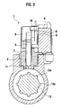
- Fig. 3 is a cross-sectional view taken along line III-III of Fig. 2.
- Fig. 4 is an enlarged schematic diagram showing the arrangement of the lock shaft 8 and a cam plate 5 at the unlocking position.
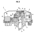
- Fig. 5 is a cross-sectional view taken along line II-II of Fig. 1 for the case where the lock shaft 8 is positioned at a locking position.
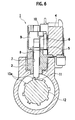
- Fig. 6 is a cross-sectional view taken along line VI-VI of Fig. 5.
- Fig. 7 is an enlarged schematic diagram showing the arrangement of the lock shaft 8 and the cam plate 5 at the locking position.
- the electric steering lock device 1 as an electric lock device includes a frame 2 and a cover 3 for covering the upper side of this frame 2.
- a motor unit 4, which is a drive source, is fixed to the upper surface of the frame 2 which is covered with the cover 3.
- the motor unit 4 includes a speed reduction mechanism, and the cam plate 5, which is a cam member, is fixed to a rotating shaft (not shown) protruding from a unit case.
- the cam plate 5 is rotated in an unlocking direction R1 and a locking direction R2 opposite to the unlocking direction R1 by the rotation of the rotating shaft.
- the peripheral surface of the cam plate 5 is formed as a sliding surface 6.
- the sliding surface 6 is set so that the distance between the sliding surface 6 and the rotation center 0 gradually changes as the rotation angle changes. Further, the sliding surface 6 is set so that the distance to a sliding point at which the undermentioned lock shaft 8 is positioned at the locking position (see Fig. 7) becomes a minimum distance, and set so that the distance to a sliding point at which the lock shaft 8 is positioned at the unlocking position (see Fig. 4) becomes a maximum distance. Details of the cam profile of the sliding surface 6 will be described in detail later.
- a slide hole 7 penetrating vertically is formed in the frame 2, a slide hole 7 penetrating vertically is formed.
- the lock shaft 8, which is a lock member, is movably placed.
- a hanger portion 9 is fixed to the upper end of the lock shaft 8.
- the lower surface of this hanger portion 9 is formed as a cam contact surface 10.
- the cam contact surface 10 is in contact with the sliding surface 6 of the cam plate 5.
- the spring force F of a spring 13 acts upon the upper surface of the hanger portion 9. By the spring force F, the lock shaft 8 is biased toward the locking position, and concurrently the cam contact surface 10 is pressed against the cam plate 5.
- an engaging pin portion 11 is provided to the lower end of the lock shaft 8.
- the lock shaft 8 moves following the sliding surface 6 of the cam plate 5, thereby moving between the locking position shown in Figs. 5 to 7 and the unlocking position shown in Figs. 2 to 4.
- the engaging pin portion 11 is thrust into a space between protrusions 12a of a steering shaft 12 as a movable member (state shown in Fig. 6) to inhibit the rotational movement of the steering shaft 12.
- the engaging pin portion 11 is positioned at a position outside the rotational locus of the protrusions 12a of the steering shaft 12 (state shown in Fig. 3) to allow the rotational movement of the steering shaft 12.
- the electric steering lock device 1 includes steering lock prevention means 20.
- This steering lock prevention means 20 includes an electromagnetic solenoid 21 fixed to the upper surface of the frame 2, covered with the cover 3. To a movable rod 21a of this electromagnetic solenoid 21, one end of a lock plate 22 is fixed. The tip of this lock plate 22 extends to a vicinity of the lock shaft 8.
- the lock shaft 8 is positioned at the unlocking position and the electromagnetic solenoid 21 is off, the lock plate 22 is thrust into a locking groove 23 of the lock shaft 8 by a spring 24, thus inhibiting the movement of the lock shaft 8.
- the electromagnetic solenoid 21 is turned on, the lock plate 22 recedes from the locking groove 23 of the lock shaft 8, thus allowing the movement of the lock shaft 8.
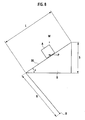
- FIG. 8 an object A corresponds to the lock shaft 8
- an inclined member B corresponds to the cam plate 5.
- the object A is mounted on the inclined surface 30 of the inclined member B which corresponds to the sliding surface 6 of the cam plate 5, and that the object A can move only in the vertical direction.
- the object A is subjected to a vertical load W (including the spring force F) and also to a horizontal load P from the inclined member B.
- the load W has a value which guarantees reliable movement if the lock shaft 8 can be moved from the locking position to the unlocking position under this load W.
- the load P is the pressing force with which the rotating cam plate 5 presses the lock shaft 8 using the sliding surface 6 thereof.
- the object A slides up on the inclined surface 30. This behavior can be considered to be the same as a displacement of the lock shaft 8 caused by the rotation of the cam plate 5.
- L be the sliding length over which the object A slides on the inclined surface 30 of the inclined member B when the inclined member B rotates by a predetermined rotation angle (e.g., 10 degrees)
- S be the amount of upward stroke of the object A
- R be the length from the rotation center 0 of the inclined member B to the sliding point of the object A.
- external forces, which act on the object A sliding on the inclined surface 30, in a direction parallel to the inclined surface 30 include the component force W ⁇ Sin ⁇ of the load W, the component force P ⁇ Cos ⁇ of the load P, and the kinetic frictional forces ⁇ W ⁇ Cos ⁇ and ⁇ P ⁇ Sin ⁇ (p is the coefficient of kinetic friction) due to reaction forces produced by the loads Wand P, respectively.
- the object A i.e., the lock shaft 8
- the object A can be moved with the rotary torque maintained constant.
- an optimum sliding point is selected for each rotation angle by increasing the rotation angle ⁇ of the cam plate 5 in steps of 10 degrees, and the sliding points are finally connected, thus creating a cam profile.
- the radial length R the sliding length L
- the shift stroke S is set at an arbitrary appropriate predetermined value S1, and the work of specifying a sliding point is performed.
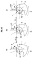
- Fig. 10(a) shows the position of the cam plate 5 for an arbitrary rotation angle ⁇ .
- Let a1 be the sliding point on the sliding surface 6 on which the lock shaft 8 slides, and let R1 be the radial length from the rotation center O to the sliding point al.
- Fig. 10(b) shows the position of the cam plate 5 for a rotation angle of ( ⁇ +10).
- the shift stroke amount S from the position for a rotation angle of ( ⁇ ) shown in Fig. 10(a) to the position for a rotation angle of ( ⁇ +10) is set at a predetermined value S1.
- Optimum values L1 and R1 i.e., ones which give a sliding point a2 for a smooth continuous cam profile, are selected from candidate values for the sliding length L and the radial length R which satisfy the aforementioned equation (2). These optimum values L1 and R1 are plotted.
- Fig. 10(c) shows the position of the cam plate 5 for a rotation angle of ( ⁇ +20).
- the shift stroke S from the position for a rotation angle of ( ⁇ +10) shown in Fig. 10(b) to the position for a rotation angle of ( ⁇ +20) is set at the predetermined value S1.
- Optimum values L2 and R2, i.e., ones which give a sliding point a3 for a smooth continuous cam profile, are selected among candidate values for the sliding length L and the radial length R which satisfy the aforementioned equation (2). These optimum values L2 and R2 are plotted. By repeating the above, a cam profile is created.
- the cam plate 5 starts rotating from a rotation angle of 0 degrees shown in Fig. 11(a), and the unlocking movement of the lock shaft 8 is started from the point for a rotation angle of 69 degrees shown in Fig. 11(b).
- a high-load region is from the point for a rotation angle of 69 degrees shown in Fig. 11 (b) to the point for a rotation angle of 179 degrees shown in Fig. 11(c), and the other region is a low-load region (almost no load).
- the unlocking movement of the lock shaft 8 is finished at the point for a rotation angle of 244 degrees shown in Fig. 11(d), and the rotation of the cam plate 5 is finished at the position for a rotation angle of 343 degrees shown in Fig. 11(e).
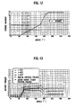
- Fig. 12 shows the shift stroke amount of the lock shaft 8 with respect to the rotation angle of the cam plate 5.
- the horizontal axis represents the rotation angle of the cam plate 5, and the vertical axis represents the displacement stroke amount of the lock shaft 8.
- the horizontal axis represents the rotation angle of the cam plate 5, and the vertical axis represents the rotary torque of the cam plate 5.
- the cam profile is set so that the rotary torque of the cam plate 5 necessary for moving the lock shaft 8 gradually increases, and, in the range in which the rotation angle is between approximately 80 degrees and 179 degrees, the cam profile is set so that the rotary torque of the cam plate 5 necessary for moving the lock shaft 8 can be maintained at approximately a constant value.
- This constant value is set at, for example, the maximum allowable value of the rotary torque of the motor unit 4 or a value slightly less than this.
- the cam profile of the cam plate 5 is set to be one in which importance is placed on the displacement stroke amount of the lock shaft 8.
- the lock shaft 8 is positioned at the locking position shown in Figs. 5 to 7, and the rotation of the steering shaft 12 is locked.
- the theft of the vehicle can be prevented.
- the lock plate 22 coupled to the electromagnetic solenoid 21 of the steering lock prevention means 20 is locked with the locking groove 23 of the lock shaft 8 by the biasing force of the spring 24.
- the lock shaft 8 is maintained at the unlocking position, and the free rotation of the steering shaft 12 is allowed.
- the electromagnetic solenoid 21 of the steering lock prevention means 20 When the engine is stopped, the electromagnetic solenoid 21 of the steering lock prevention means 20 is turned on, the lock plate 22 is removed from the locking groove 23 of the lock shaft 8, and the motor unit 4 is driven to rotate the cam plate 5 in the locking direction R2.
- the lock shaft 8 moves to the locking position shown in Figs. 5 to 7, and the rotation of the steering shaft 12 is inhibited.
- the cam plate 5 only needs a rotary torque of a certain value or less in order to displace the lock shaft 8 from the locking position to the unlocking position, and the motor unit 4 may be selected with reference to the rotary torque of the certain value or less. Accordingly, the lock shaft 8 can be displaced by the motor unit 4 having a small rotary torque.
- the cam profile of the sliding surface 6 of the cam plate 5 is set so that the rotary torque of the cam plate 5 necessary for moving the lock shaft 8 can be maintained at approximately a constant value over a certain range (from 80 degrees to 179 degrees) of rotation angles of the cam plate 5. Accordingly, the lock shaft 8 can be efficiently moved by setting the constant value at the maximum allowable value of the rotary torque of the motor unit 4 or a value slightly less than this.
- the shift stroke amount S of the lock shaft 8 per rotation angle of the cam plate 5 is maintained at approximately a constant value, and the cam profile is set by selecting optimum values of the length R from the rotation center O of the cam plate 5 to the sliding point and the sliding length L of the cam contact surface 10 of the lock shaft 8 per rotation angle of the cam plate 5, which optimum values make the cam profile of the sliding surface 6 a smooth continuous surface, from candidate values which satisfy a predetermined relational expression. Accordingly, the cam profile of the sliding surface 6 can be determined by a simple procedure.
- the region in which the rotary torque of the cam plate 5 is set to be approximately a constant value in the cam profile is limited to the high-load range within the range of movement of the lock shaft 8 from the locking position to the unlocking position. Furthermore, in the low-load range, the cam profile of the sliding surface 6 is set to be one in which importance is placed on the shift stroke amount of the lock shaft 8. Accordingly, the lock shaft 8 can be moved using the motor unit 4 having a small rotary torque. Also, a large shift stroke amount of the lock shaft 8 can be ensured.
- the above-described constitution of the cam plate 5 and the steering lock prevention means 20 doubly prevent the risk of locking the steering shaft 12 during the driving or the like of the vehicle.
- the cam plate 5 prevents a situation in which the lock shaft 8 locks the steering shaft 12 in cases including one where the steering lock prevention means 20 does not normally work due to some cause.
- the steering lock prevention means 20 prevents a situation in which the lock shaft 8 biased by the spring 13 locks the steering shaft 12 in, for example, the case where the cam plate 5 almost starts rotating unexpectedly due to a malfunction in the motor unit 4, or the case where the lock shaft 8 is unexpectedly detached from the cam plate 5 due to strong vibrations or the like during driving.
- the steering shaft 12 can be prevented from being locked during the driving of the vehicle even if the steering lock prevention means 20 is not provided. Not providing the steering lock prevention means 20 can make the electric steering lock device 1 more compact, lighter, less expensive, and the like.
- An electric lock device in which a lock member can be moved using a drive source having a small rotary torque.
Landscapes
- Engineering & Computer Science (AREA)
- Mechanical Engineering (AREA)
- Lock And Its Accessories (AREA)
Applications Claiming Priority (2)
| Application Number | Priority Date | Filing Date | Title |
|---|---|---|---|
| JP2004297907A JP3808889B2 (ja) | 2004-10-12 | 2004-10-12 | 電動ロック装置 |
| PCT/JP2005/017253 WO2006040906A1 (fr) | 2004-10-12 | 2005-09-20 | Dispositif de serrure electrique |
Publications (3)
| Publication Number | Publication Date |
|---|---|
| EP1800976A1 true EP1800976A1 (fr) | 2007-06-27 |
| EP1800976A4 EP1800976A4 (fr) | 2009-11-04 |
| EP1800976B1 EP1800976B1 (fr) | 2014-01-29 |
Family
ID=36148205
Family Applications (1)
| Application Number | Title | Priority Date | Filing Date |
|---|---|---|---|
| EP20050785340 Expired - Lifetime EP1800976B1 (fr) | 2004-10-12 | 2005-09-20 | Dispositif de serrure electrique |
Country Status (6)
| Country | Link |
|---|---|
| US (1) | US8136376B2 (fr) |
| EP (1) | EP1800976B1 (fr) |
| JP (1) | JP3808889B2 (fr) |
| KR (1) | KR100826750B1 (fr) |
| CN (1) | CN100439163C (fr) |
| WO (1) | WO2006040906A1 (fr) |
Cited By (2)
| Publication number | Priority date | Publication date | Assignee | Title |
|---|---|---|---|---|
| EP2666939A3 (fr) * | 2012-05-24 | 2017-12-27 | dormakaba Deutschland GmbH | Serrure pour une porte |
| DE102013226726B4 (de) | 2013-12-19 | 2018-12-20 | Kendrion Kuhnke Automation Gmbh | Verriegelungsvorrichtung mit einer motorisch angetriebenen Verriegelungskulisse |
Families Citing this family (8)
| Publication number | Priority date | Publication date | Assignee | Title |
|---|---|---|---|---|
| JP4863839B2 (ja) * | 2006-10-26 | 2012-01-25 | 株式会社アルファ | 電動ステアリングロック装置 |
| CN101732069B (zh) * | 2008-11-27 | 2013-07-17 | 株式会社东芝 | 台车及超声波诊断装置 |
| JP5360017B2 (ja) * | 2010-08-20 | 2013-12-04 | 日本精工株式会社 | ステアリング装置 |
| US8624172B2 (en) * | 2010-10-13 | 2014-01-07 | Woodward Hrt, Inc. | Shift lock assembly |
| DE102012207442A1 (de) * | 2012-05-04 | 2013-11-07 | Kiekert Ag | Schloss für eine Klappe oder Tür |
| EP2997209B1 (fr) * | 2013-05-15 | 2021-02-17 | TriTeq Lock and Security LLC | Serrure |
| JP6689739B2 (ja) * | 2016-12-26 | 2020-04-28 | 株式会社東海理化電機製作所 | シフト装置 |
| US12359465B2 (en) | 2021-02-16 | 2025-07-15 | Triteq Lock And Security, Llc | Lock |
Family Cites Families (17)
| Publication number | Priority date | Publication date | Assignee | Title |
|---|---|---|---|---|
| US1806253A (en) * | 1927-06-27 | 1931-05-19 | Fairchild Lock Corp | Cam snap lock |
| JP2530045Y2 (ja) * | 1990-11-09 | 1997-03-26 | 株式会社東海理化電機製作所 | ステアリングロック装置 |
| JPH07108652B2 (ja) * | 1990-11-20 | 1995-11-22 | 重宣 黒木 | 車両用ステアリングロック装置 |
| JP2537511Y2 (ja) * | 1991-03-15 | 1997-06-04 | 株式会社東海理化電機製作所 | ステアリングロック装置 |
| JPH06158924A (ja) * | 1992-11-25 | 1994-06-07 | Tokai Rika Co Ltd | ステアリングロック装置 |
| FR2739072B1 (fr) | 1995-09-21 | 1997-10-24 | Valeo Securite Habitacle | Antivol motorise de direction de vehicule automobile |
| EP1386799B1 (fr) * | 1997-03-28 | 2005-10-26 | HONDA LOCK MFG. Co., LTD. | Dispositif de verrouillage de la direction |
| JP3592941B2 (ja) * | 1998-11-24 | 2004-11-24 | 株式会社東海理化電機製作所 | ステアリングロック装置 |
| DE10061960C2 (de) | 2000-12-13 | 2003-04-03 | Huf Huelsbeck & Fuerst Gmbh | Vorrichtung zur Blockierung der Lenksäule eines Kraftfahrzeuges |
| US6571587B2 (en) * | 2001-01-09 | 2003-06-03 | Strattec Security Corporation | Steering column lock apparatus and method |
| JP2002234419A (ja) * | 2001-02-09 | 2002-08-20 | Tokai Rika Co Ltd | 電子式ステアリングロック機構 |
| DE10119267C1 (de) * | 2001-04-20 | 2002-11-21 | Huf Huelsbeck & Fuerst Gmbh | Lenkschloss für Fahrzeuge |
| JP3808789B2 (ja) * | 2002-03-22 | 2006-08-16 | 株式会社東海理化電機製作所 | 電動ステアリングロック装置 |
| JP2003341479A (ja) * | 2002-05-30 | 2003-12-03 | Tokai Rika Co Ltd | 電子式車両盗難防止装置 |
| JP4248948B2 (ja) * | 2003-06-13 | 2009-04-02 | 株式会社アルファ | 電動ステアリングロック装置 |
| US7140213B2 (en) | 2004-02-21 | 2006-11-28 | Strattec Security Corporation | Steering column lock apparatus and method |
| US7596976B2 (en) * | 2007-11-30 | 2009-10-06 | Alpha Corporation | Electric steering lock device |
-
2004
- 2004-10-12 JP JP2004297907A patent/JP3808889B2/ja not_active Expired - Fee Related
-
2005
- 2005-09-20 CN CNB2005800314826A patent/CN100439163C/zh not_active Expired - Fee Related
- 2005-09-20 US US11/659,999 patent/US8136376B2/en not_active Expired - Fee Related
- 2005-09-20 WO PCT/JP2005/017253 patent/WO2006040906A1/fr not_active Ceased
- 2005-09-20 KR KR1020077005592A patent/KR100826750B1/ko not_active Expired - Fee Related
- 2005-09-20 EP EP20050785340 patent/EP1800976B1/fr not_active Expired - Lifetime
Cited By (2)
| Publication number | Priority date | Publication date | Assignee | Title |
|---|---|---|---|---|
| EP2666939A3 (fr) * | 2012-05-24 | 2017-12-27 | dormakaba Deutschland GmbH | Serrure pour une porte |
| DE102013226726B4 (de) | 2013-12-19 | 2018-12-20 | Kendrion Kuhnke Automation Gmbh | Verriegelungsvorrichtung mit einer motorisch angetriebenen Verriegelungskulisse |
Also Published As
| Publication number | Publication date |
|---|---|
| CN100439163C (zh) | 2008-12-03 |
| KR100826750B1 (ko) | 2008-04-30 |
| US20070295044A1 (en) | 2007-12-27 |
| JP2006111058A (ja) | 2006-04-27 |
| KR20070045318A (ko) | 2007-05-02 |
| WO2006040906A1 (fr) | 2006-04-20 |
| JP3808889B2 (ja) | 2006-08-16 |
| CN101022980A (zh) | 2007-08-22 |
| EP1800976B1 (fr) | 2014-01-29 |
| EP1800976A4 (fr) | 2009-11-04 |
| US8136376B2 (en) | 2012-03-20 |
Similar Documents
| Publication | Publication Date | Title |
|---|---|---|
| US5379872A (en) | Locking arrangement for a selector lever of an automatic motor vehicle transmission | |
| US4854193A (en) | Key interlock system for automatic floor mounted transmission shifter | |
| EP1800976B1 (fr) | Dispositif de serrure electrique | |
| EP2660112A1 (fr) | Verrouillage de parc pour transmission étroite | |
| JP2842951B2 (ja) | 自動変速機のキーインターロック装置 | |
| GB2337031A (en) | Automotive vehicle steering column lock mechanism | |
| EP1783016B1 (fr) | Dispositif de blocage de direction electrique | |
| EP1783015A1 (fr) | Dispositif de blocage de direction electrique | |
| KR100686997B1 (ko) | 전동 스티어링 록 장치 | |
| EP3412509B1 (fr) | Mécanisme actionneur pour un ensemble de rétroviseur repliable | |
| EP2896559B1 (fr) | Commande prioritaire manuelle pour actionneur de direction | |
| US20230373552A1 (en) | Adjustment device for a steering wheel of a motor vehicle | |
| EP3747713B1 (fr) | Agencement de verrouillage de stationnement | |
| JP4968085B2 (ja) | パーキング切替装置 | |
| US6634480B2 (en) | Driving device | |
| EP0154046B1 (fr) | Construction d'un toit ouvrant pour véhicules | |
| EP3419865B1 (fr) | Dispositif de verrouillage de colonne de direction pour un véhicule automobile | |
| JP2000225923A (ja) | エンジン始動装置 | |
| KR100808748B1 (ko) | 전동 스티어링 록 장치 | |
| JP2908453B2 (ja) | 自動変速機のシフトレバー制御装置 | |
| JPH0646749Y2 (ja) | 車両用シフトロック装置 | |
| JPH04181056A (ja) | 自動変速機のシフトロック解除装置 |
Legal Events
| Date | Code | Title | Description |
|---|---|---|---|
| PUAI | Public reference made under article 153(3) epc to a published international application that has entered the european phase |
Free format text: ORIGINAL CODE: 0009012 |
|
| 17P | Request for examination filed |
Effective date: 20070313 |
|
| AK | Designated contracting states |
Kind code of ref document: A1 Designated state(s): DE FR GB |
|
| DAX | Request for extension of the european patent (deleted) | ||
| RBV | Designated contracting states (corrected) |
Designated state(s): DE FR GB |
|
| A4 | Supplementary search report drawn up and despatched |
Effective date: 20091007 |
|
| 17Q | First examination report despatched |
Effective date: 20100203 |
|
| GRAP | Despatch of communication of intention to grant a patent |
Free format text: ORIGINAL CODE: EPIDOSNIGR1 |
|
| INTG | Intention to grant announced |
Effective date: 20130819 |
|
| GRAS | Grant fee paid |
Free format text: ORIGINAL CODE: EPIDOSNIGR3 |
|
| GRAA | (expected) grant |
Free format text: ORIGINAL CODE: 0009210 |
|
| AK | Designated contracting states |
Kind code of ref document: B1 Designated state(s): DE FR GB |
|
| REG | Reference to a national code |
Ref country code: GB Ref legal event code: FG4D |
|
| REG | Reference to a national code |
Ref country code: DE Ref legal event code: R079 Ref document number: 602005042636 Country of ref document: DE Free format text: PREVIOUS MAIN CLASS: B60R0025020000 Ipc: B60R0025400000 |
|
| REG | Reference to a national code |
Ref country code: DE Ref legal event code: R096 Ref document number: 602005042636 Country of ref document: DE Effective date: 20140313 Ref country code: DE Ref legal event code: R079 Ref document number: 602005042636 Country of ref document: DE Free format text: PREVIOUS MAIN CLASS: B60R0025020000 Ipc: B60R0025400000 Effective date: 20140131 |
|
| REG | Reference to a national code |
Ref country code: DE Ref legal event code: R097 Ref document number: 602005042636 Country of ref document: DE |
|
| PLBE | No opposition filed within time limit |
Free format text: ORIGINAL CODE: 0009261 |
|
| STAA | Information on the status of an ep patent application or granted ep patent |
Free format text: STATUS: NO OPPOSITION FILED WITHIN TIME LIMIT |
|
| 26N | No opposition filed |
Effective date: 20141030 |
|
| REG | Reference to a national code |
Ref country code: DE Ref legal event code: R097 Ref document number: 602005042636 Country of ref document: DE Effective date: 20141030 |
|
| REG | Reference to a national code |
Ref country code: FR Ref legal event code: PLFP Year of fee payment: 12 |
|
| REG | Reference to a national code |
Ref country code: FR Ref legal event code: PLFP Year of fee payment: 13 |
|
| PGFP | Annual fee paid to national office [announced via postgrant information from national office to epo] |
Ref country code: CZ Payment date: 20170512 Year of fee payment: 10 |
|
| REG | Reference to a national code |
Ref country code: FR Ref legal event code: PLFP Year of fee payment: 14 |
|
| GBPC | Gb: european patent ceased through non-payment of renewal fee |
Effective date: 20180920 |
|
| PG25 | Lapsed in a contracting state [announced via postgrant information from national office to epo] |
Ref country code: GB Free format text: LAPSE BECAUSE OF NON-PAYMENT OF DUE FEES Effective date: 20180920 |
|
| PGFP | Annual fee paid to national office [announced via postgrant information from national office to epo] |
Ref country code: DE Payment date: 20190925 Year of fee payment: 15 Ref country code: FR Payment date: 20190925 Year of fee payment: 15 |
|
| REG | Reference to a national code |
Ref country code: DE Ref legal event code: R119 Ref document number: 602005042636 Country of ref document: DE |
|
| PG25 | Lapsed in a contracting state [announced via postgrant information from national office to epo] |
Ref country code: DE Free format text: LAPSE BECAUSE OF NON-PAYMENT OF DUE FEES Effective date: 20210401 Ref country code: FR Free format text: LAPSE BECAUSE OF NON-PAYMENT OF DUE FEES Effective date: 20200930 |