EP1801047A2 - Dispositif de préhension pour des objets plats empilés - Google Patents
Dispositif de préhension pour des objets plats empilés Download PDFInfo
- Publication number
- EP1801047A2 EP1801047A2 EP06022841A EP06022841A EP1801047A2 EP 1801047 A2 EP1801047 A2 EP 1801047A2 EP 06022841 A EP06022841 A EP 06022841A EP 06022841 A EP06022841 A EP 06022841A EP 1801047 A2 EP1801047 A2 EP 1801047A2
- Authority
- EP
- European Patent Office
- Prior art keywords
- stack
- support elements
- gripper
- transfer unit
- printed products
- Prior art date
- Legal status (The legal status is an assumption and is not a legal conclusion. Google has not performed a legal analysis and makes no representation as to the accuracy of the status listed.)
- Granted
Links
Images
Classifications
-
- B—PERFORMING OPERATIONS; TRANSPORTING
- B65—CONVEYING; PACKING; STORING; HANDLING THIN OR FILAMENTARY MATERIAL
- B65G—TRANSPORT OR STORAGE DEVICES, e.g. CONVEYORS FOR LOADING OR TIPPING, SHOP CONVEYOR SYSTEMS OR PNEUMATIC TUBE CONVEYORS
- B65G47/00—Article or material-handling devices associated with conveyors; Methods employing such devices
- B65G47/74—Feeding, transfer, or discharging devices of particular kinds or types
- B65G47/90—Devices for picking-up and depositing articles or materials
- B65G47/902—Devices for picking-up and depositing articles or materials provided with drive systems incorporating rotary and rectilinear movements
-
- B—PERFORMING OPERATIONS; TRANSPORTING
- B65—CONVEYING; PACKING; STORING; HANDLING THIN OR FILAMENTARY MATERIAL
- B65G—TRANSPORT OR STORAGE DEVICES, e.g. CONVEYORS FOR LOADING OR TIPPING, SHOP CONVEYOR SYSTEMS OR PNEUMATIC TUBE CONVEYORS
- B65G57/00—Stacking of articles
- B65G57/02—Stacking of articles by adding to the top of the stack
- B65G57/03—Stacking of articles by adding to the top of the stack from above
-
- B—PERFORMING OPERATIONS; TRANSPORTING
- B65—CONVEYING; PACKING; STORING; HANDLING THIN OR FILAMENTARY MATERIAL
- B65G—TRANSPORT OR STORAGE DEVICES, e.g. CONVEYORS FOR LOADING OR TIPPING, SHOP CONVEYOR SYSTEMS OR PNEUMATIC TUBE CONVEYORS
- B65G61/00—Use of pick-up or transfer devices or of manipulators for stacking or de-stacking articles not otherwise provided for
Definitions
- the present invention relates to a stack gripper, in particular for unbound printed products, with a first and a second pair of juxtaposed support elements, which are adjustably mounted on a cross member.
- a stack gripper is for example from the US Pat. No. 6,871,893 B2 known.
- the stack gripper it is possible, for example, after gripping the stack and during the transfer of the stack to a pallet to eliminate the distance between the two stacks, so that when you place the double stack on the pallet of the available space is used in the best possible way.
- the support elements of a pair can be attached to a traverse manually adjustable, wherein the traverse of the drive in each case in the direction of the other pair or in the direction of the other traverse is movable.
- This embodiment on the one hand represents a structurally simple and thus cost-effective solution.
- it is ensured in a simple manner that stacks of different formats can be handled reliably, since the support elements of a pair are fastened to the traverse in a manually adjustable manner, ie. the relative distance between two adjacent support elements of a pair is adjustable.
- a vertically adjustable pressure element is provided between the support elements of each pair. With such a pressure element, the stack of particular unbound printed products can be fixed from above, so that the stack gripper can be moved at comparatively high speeds in the direction of the pallet or in the direction of the dispensing position.
- a guide of such a pressure element is integrated in a holder of a support element. In this way, no separate construction must be provided for the support of the pressure element.
- the support elements have flexible support bands that roll on the front end of the support elements, a particularly gentle handling of the stack is guaranteed because there is no relative movement between the stack and stack support when the support elements are withdrawn to store the stack.
- a rear stop is provided for the printed products, wherein a sensor detects a striking of printed products on the stop.
- a sensor detects a striking of printed products on the stop.
- a stack of printed products is applied to a pair of support elements and then the two pairs are moved towards each other by means of the drive of the adjustment device, after a vertically adjustable pressure element lowered onto the top of each stack has been.
- the drive can be actuated when the stack gripper is moved by means of a manipulator, for example a robot arm, from a transfer position to a storage position.
- the vertically adjustable pressure element is pressed more strongly against the stack during the movement of the manipulator or the stack gripper than in the storage position in which the support elements are pulled away from under the stack. This procedure ensures that the individual printed products of the stacks do not shift during the movement of the stack gripper and that a gentle stacking of the stacks can take place on the pallet or on stacks already arranged thereon.
- this relates to a transfer unit for a stack gripper of the type described above, wherein this transfer unit has a displacement unit on which a carriage is arranged horizontally displaceable. On the carriage at least two storage means are provided side by side for each stack, and it is further arranged on the carriage ejector, which allows ejection of stacks located on the storage means on the support elements of the stacking gripper.
- this transfer unit it is possible to form stacks of paper products, which are conveyed by a conveyor line, into a double stack and then transfer it to the stack gripper.
- an incoming stack is first arranged on a storage means and then the carriage is moved horizontally, so that the subsequently conveyed stack can be arranged on the adjacent storage means.
- the two can Stack of the ejector are ejected onto the support elements of the stack gripper.
- the storage means may comprise parallel juxtaposed conveyor belts for transferring the stacks from the transfer unit to the stack gripper.
- At least one vertically and horizontally movable ejector is provided, which supports the ejection process. Due to the vertical movability of the ejector, it can be mounted above the filing means and lowered horizontally for ejection.
- a braking zone delimited by a first and a second sensor can be provided on the carriage in which the conveyor belts are driven at reduced speed.
- a braking distance allows a high processing speed, since the stack can be initially promoted with the conveyor line in the transfer unit and decelerated only on reaching the braking distance to a very low speed and stopped when reaching the end of the braking distance.
- the distance between the storage means by an adjusting element in particular manually be adjustable, so that in the area of the transfer unit a format setting is possible.
- a stack of printed products is first conveyed onto a storage means. Subsequently, another stack of printed products is conveyed to a further storage means and then both stacks are simultaneously moved by the ejection device on the support elements of the stack gripper. In this way, not only double stacks are formed in a very short time, but also pass them to the stack gripper.
- the stack which is first conveyed onto the carriage, is held fast by two pressure elements during the movement of the carriage in order to prevent damage to the stack or displacement of the individual printed products. It is likewise advantageous if the further stack is aligned by lateral pressure elements before the ejection device is actuated in order to ensure the best possible straightness of the stack.
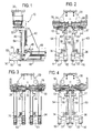
- the stack gripper 10 shown in FIGS. 1 to 4 has a first pair of side-by-side support elements 11 and 12 and a second pair of side-by-side support elements 14 and 16, the two pairs of support elements via vertical supports 13, 19, 15 and 17 are adjustably mounted on a cross member 18.
- the cross member 18 is in turn attached to a gripper flange 20 with which the stack gripper 10 can be mounted on a robot arm 22 (see Fig. 8).
- Each pair of support members 11, 12 and 14, 16 is attached to an associated crossbar 24 and 26 manually adjustable to ensure a format adjustment.
- each cross member 24 and 26 of an adjusting device horizontally displaceable along the cross member 18, so that the two pairs of support elements toward each other and from each other can be moved without the relative distance or the lateral distance of the support elements 11 and 12 or 14 and 16 changes.
- the adjusting device has a drive in the form of two pneumatic cylinders 28 and 30 (see Fig. 3) to move the two trusses 24 and 26 along a linear guide 32 which is fixed to the cross member 18.
- a vertically adjustable pressure element 34 and 36 is provided, which is in each case vertically adjustable in a linear guide 38, 40 of a pneumatic cylinder 42 (see FIG .. 1).
- the support elements 11 to 16 each include a support finger 44 which is movable horizontally via a linear guide 48 by means of a pneumatic cylinder 46.
- a deflection roller 50 is provided (in the figures, only the front deflection roller can be seen, around each of which a thin flat belt 52 is guided, whose two free ends are fixed on the gripper.)
- the pneumatic cylinder 46 is retracted, with the flat belt 52 unrolling over the deflection rollers 50 so that there is no relative movement between the upper run of the flat belt 52 and the stack.
- a stop plate 54, 56, 58 and 60 is provided on each carrier 13, 19, 15 and 17, which serves as a rear stop for the stack on the support elements 11 to 16 stack S 1 and S2.
- a sensor 62 is further provided in the form of a laser reflection light barrier, which detects a striking of printed products, that is a striking of the stack S 1 to the stop plates 54 and 56.
- a laser reflection light barrier 64 which detects a striking of the stack S2 on the stop plates 58 and 60, is fastened to the carrier 15.
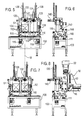
- FIG. 5 to 8 show a transfer unit for the stack gripper described above, which serves on the one hand to form double stacks from printed products which have been conveyed in a single conveying line and subsequently to transfer these double stacks to the stack gripper.
- Fig. 8 shows a side view of the transfer unit, wherein the stack gripper 10, which has been described above, has been moved by means of an only indicated robot arm 22 in the transfer position, in which the double stack formed can be taken.
- the preferred embodiment of a transfer unit comprises a base frame 100, on which a carriage 110 is horizontally displaceable by means of a pneumatic cylinder 111 from the right position shown in FIG. 5 to the left position shown in FIG ,
- two storage means for one stack S 1 and S2 are provided parallel to each other, each comprising three conveyor belts 112 and 114 in the illustrated embodiment, wherein the conveyor belts 112 by a motor 116 and the conveyor belts 114 are driven by a motor 118.
- the stack S 1 can be deposited on the shelf formed by the conveyor belts 112, while the stack S 2 (see FIG. 7) can be deposited on the conveyor belts 114.
- the horizontal relative position of the individual conveyor belts 112 and 114 on the carriage 110 is adjustable by means of a handwheel 115 for format adjustment.
- both storage means 112 and 114 two pressure plates 120, 121 and 122 and 123 are arranged in each case.
- the two outermost pressure plates 120 and 123 can be moved in the direction of the stacks by pneumatic cylinders 124 and 126, while the two inner pressure plates 121 and 122 are moved in the direction of the stacks by pneumatic cylinders 128 and 130 (see Fig. 7) arranged above the pressure plates can be.
- an ejection device which has two ejection plates 132 and 134, which are each vertically displaceable via a pneumatic cylinder 136 and 138. Furthermore, both ejection plates 132 and 134 are horizontally movable in the ejection direction via an associated pneumatic cylinder 140 (see FIGS. 5 and 7,
- a braking path is provided on the carriage 110, which is delimited by a first light barrier 142 (see FIG. 6) and a second light barrier 144. These two light barriers detect the retraction of a stack separately for each support, wherein the stack is decelerated when passing the light barrier 142 and stopped when the light barrier 144 is reached.
- the center axis of an incoming conveyor line is shown in phantom and designated by the reference M.
- the line M i. the central axis of the incoming conveyor line respectively through the center of the two storage means, when the carriage is in its two end positions.
- first a first stack S 1 is conveyed from an incoming single conveyor line (not shown) into the transfer unit, and the stack S 1 is taken over by the conveyor belts 112 and transported at the speed of the conveyor line up to the first light barrier 142.
- the speed of the conveyor belts is greatly reduced and the stack S 1 is promoted to the second light barrier 144 at this low speed.
- the stack is stopped, i. the conveyor belts 112 are stopped.
- the stack S 1 located on the support formed by the conveyor belts 112 can be laterally aligned and held by means of the pressure plates 120 and 121 by activating the pneumatic cylinders 124 and 128 (FIG. 7).
- the entire unit located on the carriage 110 is then moved to the position shown in FIG. 7, wherein the pressure plates 120 and 121 remain attached to the stack S 1.
- the center of the support formed by the conveyor belts 114 is located on the center line M of the incoming conveyor line, so that a subsequent stack S2 enter the transfer unit and can be taken over by the conveyor belts 114.
- the stack S2 is aligned by the pressure plates 122 and 123 by the pneumatic cylinders 130 and 126 are actuated.
- the ejection plates 132 and 134 are lowered by operating the pneumatic cylinder 136 and 138 down, whereupon by pressing the pneumatic cylinder 140, the two stacks S 1 and S2 can be transferred to the stack gripper 10 of the robot arm 22 previously in the appropriate Transfer position has been moved.
- the pressure plates 120 to 123 are slightly withdrawn, so that they no longer hold the two stacks S 1 and S2, but provide a guide.
- the transfer belts 112 and 114 are moved during the transfer process in order to prevent a relative movement between the two stacks S 1 and S2 and the conveyor belts.
- the sensors 62 and 64 FIG. 2 when the stacks have reached the stop plates 54, 56 and 58 and 60, respectively. If this is the case, the pressure elements 34 and 36 are lowered by activating the pneumatic cylinder 42, so that the position shown in FIGS. 1 to 3 is given.
- the stack gripper 10 can be moved by the robot arm 22 in the direction of the dispensing position above a pallet. During this movement, the pneumatic cylinders 28 and 30 are activated, so that the two trusses 24 and 26 can be moved towards each other, whereby the gap between the two stacks S 1 and S2 is eliminated.
- the contact pressure of the pressure elements 34 and 36 is reduced and the pneumatic cylinder 46 are activated, so that the lower run of the flat belt 52 can be withdrawn, wherein the support fingers 44 also move backwards. After the support fingers 44 have been completely withdrawn, can the stack gripper are moved by the robot arm 22 again in the direction of the transfer unit.
Landscapes
- Engineering & Computer Science (AREA)
- Mechanical Engineering (AREA)
- Pile Receivers (AREA)
- Stacking Of Articles And Auxiliary Devices (AREA)
- Discharge By Other Means (AREA)
- Advancing Webs (AREA)
- Load-Engaging Elements For Cranes (AREA)
- Fuel Cell (AREA)
- Specific Conveyance Elements (AREA)
- Sheets, Magazines, And Separation Thereof (AREA)
Priority Applications (2)
| Application Number | Priority Date | Filing Date | Title |
|---|---|---|---|
| EP08011850A EP1975096A1 (fr) | 2005-12-20 | 2006-11-02 | Dispositif de préhension pour des objets plats empilés |
| PL06022841T PL1801047T3 (pl) | 2005-12-20 | 2006-11-02 | Układarka stosów |
Applications Claiming Priority (1)
| Application Number | Priority Date | Filing Date | Title |
|---|---|---|---|
| DE102005060946A DE102005060946A1 (de) | 2005-12-20 | 2005-12-20 | Stapelgreifer |
Related Child Applications (1)
| Application Number | Title | Priority Date | Filing Date |
|---|---|---|---|
| EP08011850A Division EP1975096A1 (fr) | 2005-12-20 | 2006-11-02 | Dispositif de préhension pour des objets plats empilés |
Publications (3)
| Publication Number | Publication Date |
|---|---|
| EP1801047A2 true EP1801047A2 (fr) | 2007-06-27 |
| EP1801047A3 EP1801047A3 (fr) | 2007-09-05 |
| EP1801047B1 EP1801047B1 (fr) | 2009-07-29 |
Family
ID=37888048
Family Applications (2)
| Application Number | Title | Priority Date | Filing Date |
|---|---|---|---|
| EP08011850A Withdrawn EP1975096A1 (fr) | 2005-12-20 | 2006-11-02 | Dispositif de préhension pour des objets plats empilés |
| EP06022841A Revoked EP1801047B1 (fr) | 2005-12-20 | 2006-11-02 | Dispositif de préhension pour des objets plats empilés |
Family Applications Before (1)
| Application Number | Title | Priority Date | Filing Date |
|---|---|---|---|
| EP08011850A Withdrawn EP1975096A1 (fr) | 2005-12-20 | 2006-11-02 | Dispositif de préhension pour des objets plats empilés |
Country Status (7)
| Country | Link |
|---|---|
| US (1) | US7628575B2 (fr) |
| EP (2) | EP1975096A1 (fr) |
| AT (1) | ATE437827T1 (fr) |
| DE (2) | DE102005060946A1 (fr) |
| DK (1) | DK1801047T3 (fr) |
| ES (1) | ES2328055T3 (fr) |
| PL (1) | PL1801047T3 (fr) |
Cited By (6)
| Publication number | Priority date | Publication date | Assignee | Title |
|---|---|---|---|---|
| EP2072430A1 (fr) | 2007-12-20 | 2009-06-24 | Müller Martini Holding AG | Dispositif de saisie de paquet pour un dispositif de palettisation et procédé de palettisation de paquets |
| EP2098465A1 (fr) | 2008-03-05 | 2009-09-09 | Müller Martini Holding AG | Station de réception d'un dispositif de palettisation de paquets et procédé de transmission de paquets à un crochet doté d'une telle station de réception |
| EP2110348A1 (fr) | 2008-04-17 | 2009-10-21 | Müller Martini Holding AG | Station de réception et dispositif de saisie de paquet d'un dispositif de palettisation et procédé de transmission de paquets d'une station de réception vers un dispositif de saisie de paquet |
| DE102009022249A1 (de) * | 2009-05-20 | 2010-11-25 | E.C.H. Will Gmbh | Übergabevorrichtung zur Übergabe eines durch mehrere Blattlagen gebildeten Stapels |
| EP3909894A1 (fr) * | 2020-05-12 | 2021-11-17 | SSI Schäfer Automation GmbH (DE) | Dispositif, système et procédé de stockage et de préparation de commandes des objets |
| IT202300021768A1 (it) * | 2023-10-19 | 2025-04-19 | Joytek S R L Semplificata | Sistema per prelevare e trasportare una serie di elementi lastriformi. |
Families Citing this family (8)
| Publication number | Priority date | Publication date | Assignee | Title |
|---|---|---|---|---|
| WO2009038399A2 (fr) * | 2007-09-20 | 2009-03-26 | Posco | Appareil de contrôle de la position de griffes de grue en fonction de la flexion des dalles à transporter et procédé associé |
| DE102007046919B4 (de) * | 2007-09-28 | 2010-07-08 | Dematic Gmbh & Co. Kg | Greifer zum automatischen Ergreifen von Packeinheiten |
| ATE551285T1 (de) * | 2008-09-17 | 2012-04-15 | Bielomatik Leuze Gmbh & Co Kg | Sammel- und transportvorrichtung für durch blattlagen gebildete stapel |
| NL2002131C (nl) * | 2008-10-23 | 2010-04-26 | Rsw Ip B V | Inrichting voor het stapelen van objecten. |
| TWI538871B (zh) * | 2012-03-28 | 2016-06-21 | 巴柏斯特麥克斯合資公司 | 用於轉換機的非間斷齒條裝置 |
| KR101848412B1 (ko) | 2016-08-19 | 2018-05-24 | 한양대학교 에리카산학협력단 | 쓰레기 수거 시스템 |
| CN109436826A (zh) * | 2018-11-26 | 2019-03-08 | 佛山市金广豪装饰材料有限公司 | 一种用于生产铝扣板的集料堆叠装置 |
| DE102023127730A1 (de) * | 2023-10-11 | 2025-04-17 | Multivac Sepp Haggenmüller Se & Co. Kg | Greiferanordnung mit hintereinanderliegenden Produktaufnahmen |
Family Cites Families (22)
| Publication number | Priority date | Publication date | Assignee | Title |
|---|---|---|---|---|
| US2985328A (en) * | 1956-02-28 | 1961-05-23 | Fitch Clifford Kingsbury | Fork lift trucks |
| US3131819A (en) * | 1961-04-14 | 1964-05-05 | Clark Aiken Company | Shuttle piler |
| US3977671A (en) * | 1973-10-03 | 1976-08-31 | Ruel E. Taylor, Inc. | Method and apparatus for forming a plurality of even-edged piles of flexible sheets |
| FR2322085A1 (fr) * | 1975-08-27 | 1977-03-25 | Bergerat Monnoyeur Sa | Porte-fourches oscillant et a correction d'assiette pour elevateur de palettes |
| AT342500B (de) * | 1976-03-15 | 1978-04-10 | Krapinger Heinz | Gabel fur gabelstapler |
| DE3420005C2 (de) * | 1984-05-29 | 1994-10-06 | Kaup Gmbh & Co Kg | Gabelzinkenverstellgerät für Gabelstapler |
| US4588070A (en) * | 1984-11-13 | 1986-05-13 | The Dow Chemical Company | Bag transfer device |
| DE3736759A1 (de) * | 1987-10-30 | 1989-05-11 | Hoechst Ag | Plattenstapler |
| US5562403A (en) * | 1991-02-11 | 1996-10-08 | Winski; Ernest P. | Load forming apparatus and methods |
| US5271706A (en) * | 1991-10-31 | 1993-12-21 | Hkm Corporation | Self-loading paper transport system |
| DE4136218A1 (de) * | 1991-11-02 | 1993-05-06 | Hans H. Meyer Gmbh, 3320 Salzgitter, De | Parallel-armfuehrungssystem und arbeitsverfahren zur seitenverstellung von parallelen tragarmen |
| DE4427703A1 (de) * | 1994-08-04 | 1996-02-15 | Hagen Gaemmerler | Vorrichtung zum Entnehmen eines Stapels von flächenähnlichen Produkten aus einer Sammelstelle |
| US5628539A (en) * | 1995-08-03 | 1997-05-13 | Im Engineered Product Ltd. | Robotic gripping device |
| DE19626802A1 (de) * | 1996-07-03 | 1998-01-08 | Gaemmerler Hagen | Stapelgreifer |
| US6106219A (en) * | 1999-01-20 | 2000-08-22 | John Robert Newsome | Stack forming and conveying apparatus |
| IT1315340B1 (it) * | 2000-05-18 | 2003-02-10 | Mariani Sas Di Mariani Federic | Testata di presa per movimentare pile di segnature sfuse foglidepliants pubblicitari ed altri prodotti simili. |
| DE10154842C2 (de) * | 2001-11-08 | 2003-09-04 | Kaup Gmbh & Co Kg | Anbaugerät für Hubmasten, insbesondere für Hubstaplerfahrzeuge |
| US6871893B2 (en) | 2001-11-14 | 2005-03-29 | Gammerler Corporation | Apparatus and method for carrying signature bundles |
| DE10214684A1 (de) * | 2002-03-28 | 2003-10-09 | Bielomatik Leuze & Co | Fördereinrichtung und Verfahren zur Überführung von Stapeln aus Papier oder dgl. auf einen Abtransportförderer |
| EP1375405A1 (fr) * | 2002-06-27 | 2004-01-02 | Innopack S.r.l. | Unité de manutention d'un produit comprenant au moins une rame de feuilles |
| US7303523B2 (en) * | 2003-08-26 | 2007-12-04 | Andolfi Ceasar P | Paper-folding apparatus |
| US20050089389A1 (en) * | 2003-10-22 | 2005-04-28 | Saga Automation, Inc. | Method, system, and apparatus for securing a section of a vertical stack of generally flat sheets, cartons, and like |
-
2005
- 2005-12-20 DE DE102005060946A patent/DE102005060946A1/de not_active Withdrawn
-
2006
- 2006-11-02 ES ES06022841T patent/ES2328055T3/es active Active
- 2006-11-02 EP EP08011850A patent/EP1975096A1/fr not_active Withdrawn
- 2006-11-02 AT AT06022841T patent/ATE437827T1/de active
- 2006-11-02 EP EP06022841A patent/EP1801047B1/fr not_active Revoked
- 2006-11-02 DE DE502006004365T patent/DE502006004365D1/de active Active
- 2006-11-02 PL PL06022841T patent/PL1801047T3/pl unknown
- 2006-11-02 DK DK06022841T patent/DK1801047T3/da active
- 2006-12-15 US US11/611,636 patent/US7628575B2/en not_active Expired - Fee Related
Cited By (11)
| Publication number | Priority date | Publication date | Assignee | Title |
|---|---|---|---|---|
| EP2072430A1 (fr) | 2007-12-20 | 2009-06-24 | Müller Martini Holding AG | Dispositif de saisie de paquet pour un dispositif de palettisation et procédé de palettisation de paquets |
| US8235436B2 (en) | 2007-12-20 | 2012-08-07 | Mueller Martini Holding Ag | Bundle gripper for a palletizing machine and method for the palletizing of bundles |
| EP2098465A1 (fr) | 2008-03-05 | 2009-09-09 | Müller Martini Holding AG | Station de réception d'un dispositif de palettisation de paquets et procédé de transmission de paquets à un crochet doté d'une telle station de réception |
| JP2009208967A (ja) * | 2008-03-05 | 2009-09-17 | Muller Martini Holding Ag | パケットパレタイジング装置の受取ステーションならびにその種の受取ステーションによる把持装置へのパケットの移転方法 |
| US8152434B2 (en) | 2008-03-05 | 2012-04-10 | Müller Martini Holding AG | Double infeed stacking table with centering and method for transferring stacks to a gripper with an infeed station of this type |
| EP2110348A1 (fr) | 2008-04-17 | 2009-10-21 | Müller Martini Holding AG | Station de réception et dispositif de saisie de paquet d'un dispositif de palettisation et procédé de transmission de paquets d'une station de réception vers un dispositif de saisie de paquet |
| US8807912B2 (en) | 2008-04-17 | 2014-08-19 | Müller Martini Holding AG | Infeed station and stack gripper of a palletizing system and method for transferring stacks from an infeed station to a stack gripper |
| DE102009022249A1 (de) * | 2009-05-20 | 2010-11-25 | E.C.H. Will Gmbh | Übergabevorrichtung zur Übergabe eines durch mehrere Blattlagen gebildeten Stapels |
| DE102009022249B4 (de) * | 2009-05-20 | 2015-02-05 | E.C.H. Will Gmbh | Übergabevorrichtung zur Übergabe eines durch mehrere Blattlagen gebildeten Stapels |
| EP3909894A1 (fr) * | 2020-05-12 | 2021-11-17 | SSI Schäfer Automation GmbH (DE) | Dispositif, système et procédé de stockage et de préparation de commandes des objets |
| IT202300021768A1 (it) * | 2023-10-19 | 2025-04-19 | Joytek S R L Semplificata | Sistema per prelevare e trasportare una serie di elementi lastriformi. |
Also Published As
| Publication number | Publication date |
|---|---|
| EP1801047B1 (fr) | 2009-07-29 |
| EP1975096A1 (fr) | 2008-10-01 |
| ES2328055T3 (es) | 2009-11-06 |
| PL1801047T3 (pl) | 2009-12-31 |
| DK1801047T3 (da) | 2009-11-02 |
| ATE437827T1 (de) | 2009-08-15 |
| DE502006004365D1 (de) | 2009-09-10 |
| EP1801047A3 (fr) | 2007-09-05 |
| DE102005060946A1 (de) | 2007-06-28 |
| US7628575B2 (en) | 2009-12-08 |
| US20070154292A1 (en) | 2007-07-05 |
Similar Documents
| Publication | Publication Date | Title |
|---|---|---|
| EP2072430B1 (fr) | Dispositif de saisie de paquet pour un dispositif de palettisation et procédé de palettisation de paquets | |
| DE69518209T2 (de) | Trennvorrichtung für gruppen geschindelter formulare | |
| DE69317051T2 (de) | Speicher für bögen mit zurückziehbarer rampe | |
| EP2110348B1 (fr) | Station de palettisation et procédé de transmission de paquets d'une station de réception vers un dispositif de saisie de paquet | |
| EP2199240B1 (fr) | Dispositif destiné à la séparation de pièces | |
| EP1801047B1 (fr) | Dispositif de préhension pour des objets plats empilés | |
| DE3153613C2 (fr) | ||
| EP0450333A1 (fr) | Receveur de feuilles pour machines à imprimer | |
| DE3937995A1 (de) | Verfahren und vorrichtung zur bogenriesvereinzelung und zur riesablage | |
| CH662330A5 (de) | Einrichtung zur erzeugung von zwischenraeumen in einem bewegten strom von sich ueberlappenden papierboegen. | |
| DE3540203C2 (de) | Vorrichtung zum Fördern von Papierstapeln | |
| EP2363361A2 (fr) | Dispositif d'empilement et procédé d'empilement de pièces usinées longitudinales | |
| DE19911273C2 (de) | Verfahren und Vorrichtung zum Vereinzeln flächiger Güter | |
| EP0656307A1 (fr) | Cylindre de transport de cahiers | |
| CH648261A5 (de) | Vorrichtung zum herausloesen von mittels eines foerderers gefoerderten druckprodukten aus dem foerderstrom. | |
| EP3566985A1 (fr) | Dispositif d'empilement de plateaux pourvu d'un moyen de décharge | |
| DE4431669A1 (de) | Verfahren und Vorrichtung zum Ablegen von mit einer Druckmaschine im fortlaufenden Betrieb erstellten, unterschiedlichen Produkten | |
| EP3148789B1 (fr) | Dispositif et procédé pour transporter descorps de sacs tubulaires | |
| EP0773179A2 (fr) | Dispositif pour faire des piles auxiliaires pendant l'échange en continue de piles dans un empileur d'une machine à imprimer | |
| EP0751086B1 (fr) | Dispositif pour extraire les inclusions d'air de piles de papier | |
| DE2640853A1 (de) | Stapelvorrichtung fuer stahlprofile | |
| EP0020287A1 (fr) | Dispositif pour le désempilage de couches empilées | |
| AT408879B (de) | Vorrichtung zum seitlichen auseinanderbewegen von plattenförmigen werkstücken | |
| DE102019127347B3 (de) | Auslage und Verfahren zum Ablegen von Bogen in einer Auslage einer bogenverarbeitenden Maschine | |
| DE102009045319B4 (de) | Formateinstellvorrichtung |
Legal Events
| Date | Code | Title | Description |
|---|---|---|---|
| PUAI | Public reference made under article 153(3) epc to a published international application that has entered the european phase |
Free format text: ORIGINAL CODE: 0009012 |
|
| AK | Designated contracting states |
Kind code of ref document: A2 Designated state(s): AT BE BG CH CY CZ DE DK EE ES FI FR GB GR HU IE IS IT LI LT LU LV MC NL PL PT RO SE SI SK TR |
|
| AX | Request for extension of the european patent |
Extension state: AL BA HR MK YU |
|
| PUAL | Search report despatched |
Free format text: ORIGINAL CODE: 0009013 |
|
| AK | Designated contracting states |
Kind code of ref document: A3 Designated state(s): AT BE BG CH CY CZ DE DK EE ES FI FR GB GR HU IE IS IT LI LT LU LV MC NL PL PT RO SE SI SK TR |
|
| AX | Request for extension of the european patent |
Extension state: AL BA HR MK YU |
|
| 17P | Request for examination filed |
Effective date: 20080108 |
|
| 17Q | First examination report despatched |
Effective date: 20080207 |
|
| AKX | Designation fees paid |
Designated state(s): AT BE BG CH CY CZ DE DK EE ES FI FR GB GR HU IE IS IT LI LT LU LV MC NL PL PT RO SE SI SK TR |
|
| GRAP | Despatch of communication of intention to grant a patent |
Free format text: ORIGINAL CODE: EPIDOSNIGR1 |
|
| GRAS | Grant fee paid |
Free format text: ORIGINAL CODE: EPIDOSNIGR3 |
|
| GRAA | (expected) grant |
Free format text: ORIGINAL CODE: 0009210 |
|
| AK | Designated contracting states |
Kind code of ref document: B1 Designated state(s): AT BE BG CH CY CZ DE DK EE ES FI FR GB GR HU IE IS IT LI LT LU LV MC NL PL PT RO SE SI SK TR |
|
| REG | Reference to a national code |
Ref country code: GB Ref legal event code: FG4D Free format text: NOT ENGLISH |
|
| REG | Reference to a national code |
Ref country code: CH Ref legal event code: NV Representative=s name: DR. GRAF & PARTNER INTELLECTUAL PROPERTY Ref country code: CH Ref legal event code: EP |
|
| REG | Reference to a national code |
Ref country code: IE Ref legal event code: FG4D |
|
| REF | Corresponds to: |
Ref document number: 502006004365 Country of ref document: DE Date of ref document: 20090910 Kind code of ref document: P |
|
| REG | Reference to a national code |
Ref country code: DK Ref legal event code: T3 |
|
| REG | Reference to a national code |
Ref country code: ES Ref legal event code: FG2A Ref document number: 2328055 Country of ref document: ES Kind code of ref document: T3 |
|
| REG | Reference to a national code |
Ref country code: PL Ref legal event code: T3 |
|
| PG25 | Lapsed in a contracting state [announced via postgrant information from national office to epo] |
Ref country code: SE Free format text: LAPSE BECAUSE OF FAILURE TO SUBMIT A TRANSLATION OF THE DESCRIPTION OR TO PAY THE FEE WITHIN THE PRESCRIBED TIME-LIMIT Effective date: 20090729 Ref country code: IS Free format text: LAPSE BECAUSE OF FAILURE TO SUBMIT A TRANSLATION OF THE DESCRIPTION OR TO PAY THE FEE WITHIN THE PRESCRIBED TIME-LIMIT Effective date: 20091129 Ref country code: FI Free format text: LAPSE BECAUSE OF FAILURE TO SUBMIT A TRANSLATION OF THE DESCRIPTION OR TO PAY THE FEE WITHIN THE PRESCRIBED TIME-LIMIT Effective date: 20090729 Ref country code: LT Free format text: LAPSE BECAUSE OF FAILURE TO SUBMIT A TRANSLATION OF THE DESCRIPTION OR TO PAY THE FEE WITHIN THE PRESCRIBED TIME-LIMIT Effective date: 20090729 |
|
| PGFP | Annual fee paid to national office [announced via postgrant information from national office to epo] |
Ref country code: AT Payment date: 20091113 Year of fee payment: 4 Ref country code: DK Payment date: 20091112 Year of fee payment: 4 Ref country code: ES Payment date: 20091123 Year of fee payment: 4 |
|
| PG25 | Lapsed in a contracting state [announced via postgrant information from national office to epo] |
Ref country code: SI Free format text: LAPSE BECAUSE OF FAILURE TO SUBMIT A TRANSLATION OF THE DESCRIPTION OR TO PAY THE FEE WITHIN THE PRESCRIBED TIME-LIMIT Effective date: 20090729 Ref country code: LV Free format text: LAPSE BECAUSE OF FAILURE TO SUBMIT A TRANSLATION OF THE DESCRIPTION OR TO PAY THE FEE WITHIN THE PRESCRIBED TIME-LIMIT Effective date: 20090729 |
|
| PGFP | Annual fee paid to national office [announced via postgrant information from national office to epo] |
Ref country code: NL Payment date: 20091112 Year of fee payment: 4 Ref country code: PL Payment date: 20091027 Year of fee payment: 4 |
|
| REG | Reference to a national code |
Ref country code: IE Ref legal event code: FD4D |
|
| PG25 | Lapsed in a contracting state [announced via postgrant information from national office to epo] |
Ref country code: PT Free format text: LAPSE BECAUSE OF FAILURE TO SUBMIT A TRANSLATION OF THE DESCRIPTION OR TO PAY THE FEE WITHIN THE PRESCRIBED TIME-LIMIT Effective date: 20091129 Ref country code: BG Free format text: LAPSE BECAUSE OF FAILURE TO SUBMIT A TRANSLATION OF THE DESCRIPTION OR TO PAY THE FEE WITHIN THE PRESCRIBED TIME-LIMIT Effective date: 20091029 |
|
| PG25 | Lapsed in a contracting state [announced via postgrant information from national office to epo] |
Ref country code: RO Free format text: LAPSE BECAUSE OF FAILURE TO SUBMIT A TRANSLATION OF THE DESCRIPTION OR TO PAY THE FEE WITHIN THE PRESCRIBED TIME-LIMIT Effective date: 20090729 Ref country code: IE Free format text: LAPSE BECAUSE OF FAILURE TO SUBMIT A TRANSLATION OF THE DESCRIPTION OR TO PAY THE FEE WITHIN THE PRESCRIBED TIME-LIMIT Effective date: 20090729 Ref country code: CZ Free format text: LAPSE BECAUSE OF FAILURE TO SUBMIT A TRANSLATION OF THE DESCRIPTION OR TO PAY THE FEE WITHIN THE PRESCRIBED TIME-LIMIT Effective date: 20090729 Ref country code: EE Free format text: LAPSE BECAUSE OF FAILURE TO SUBMIT A TRANSLATION OF THE DESCRIPTION OR TO PAY THE FEE WITHIN THE PRESCRIBED TIME-LIMIT Effective date: 20090729 |
|
| PGFP | Annual fee paid to national office [announced via postgrant information from national office to epo] |
Ref country code: FR Payment date: 20091201 Year of fee payment: 4 |
|
| PLBI | Opposition filed |
Free format text: ORIGINAL CODE: 0009260 |
|
| PG25 | Lapsed in a contracting state [announced via postgrant information from national office to epo] |
Ref country code: SK Free format text: LAPSE BECAUSE OF FAILURE TO SUBMIT A TRANSLATION OF THE DESCRIPTION OR TO PAY THE FEE WITHIN THE PRESCRIBED TIME-LIMIT Effective date: 20090729 |
|
| REG | Reference to a national code |
Ref country code: CH Ref legal event code: PFA Owner name: GAEMMERLER AG Free format text: GAEMMERLER AG#LEITENSTRASSE 26#82538 GERETSRIED-GELTING (DE) -TRANSFER TO- GAEMMERLER AG#LEITENSTRASSE 26#82538 GERETSRIED-GELTING (DE) |
|
| PLAX | Notice of opposition and request to file observation + time limit sent |
Free format text: ORIGINAL CODE: EPIDOSNOBS2 |
|
| 26 | Opposition filed |
Opponent name: MUELLER MARTINI HOLDING AG Effective date: 20100422 |
|
| PG25 | Lapsed in a contracting state [announced via postgrant information from national office to epo] |
Ref country code: MC Free format text: LAPSE BECAUSE OF NON-PAYMENT OF DUE FEES Effective date: 20091130 |
|
| PGFP | Annual fee paid to national office [announced via postgrant information from national office to epo] |
Ref country code: BE Payment date: 20091110 Year of fee payment: 4 Ref country code: DE Payment date: 20100129 Year of fee payment: 4 |
|
| PLBB | Reply of patent proprietor to notice(s) of opposition received |
Free format text: ORIGINAL CODE: EPIDOSNOBS3 |
|
| PG25 | Lapsed in a contracting state [announced via postgrant information from national office to epo] |
Ref country code: GR Free format text: LAPSE BECAUSE OF FAILURE TO SUBMIT A TRANSLATION OF THE DESCRIPTION OR TO PAY THE FEE WITHIN THE PRESCRIBED TIME-LIMIT Effective date: 20091030 |
|
| RDAF | Communication despatched that patent is revoked |
Free format text: ORIGINAL CODE: EPIDOSNREV1 |
|
| REG | Reference to a national code |
Ref country code: DE Ref legal event code: R064 Ref document number: 502006004365 Country of ref document: DE Ref country code: DE Ref legal event code: R103 Ref document number: 502006004365 Country of ref document: DE |
|
| PG25 | Lapsed in a contracting state [announced via postgrant information from national office to epo] |
Ref country code: LU Free format text: LAPSE BECAUSE OF NON-PAYMENT OF DUE FEES Effective date: 20091102 |
|
| RDAG | Patent revoked |
Free format text: ORIGINAL CODE: 0009271 |
|
| STAA | Information on the status of an ep patent application or granted ep patent |
Free format text: STATUS: PATENT REVOKED |
|
| REG | Reference to a national code |
Ref country code: CH Ref legal event code: PL |
|
| REG | Reference to a national code |
Ref country code: NL Ref legal event code: V1 Effective date: 20110601 |
|
| 27W | Patent revoked |
Effective date: 20110217 |
|
| GBPR | Gb: patent revoked under art. 102 of the ep convention designating the uk as contracting state |
Effective date: 20110217 |
|
| PG25 | Lapsed in a contracting state [announced via postgrant information from national office to epo] |
Ref country code: HU Free format text: LAPSE BECAUSE OF FAILURE TO SUBMIT A TRANSLATION OF THE DESCRIPTION OR TO PAY THE FEE WITHIN THE PRESCRIBED TIME-LIMIT Effective date: 20100130 |
|
| REG | Reference to a national code |
Ref country code: DK Ref legal event code: EBP |
|
| REG | Reference to a national code |
Ref country code: DE Ref legal event code: R107 Ref document number: 502006004365 Country of ref document: DE Effective date: 20110728 |
|
| PG25 | Lapsed in a contracting state [announced via postgrant information from national office to epo] |
Ref country code: LI Free format text: LAPSE BECAUSE OF THE APPLICANT RENOUNCES Effective date: 20090729 Ref country code: CH Free format text: LAPSE BECAUSE OF THE APPLICANT RENOUNCES Effective date: 20090729 |
|
| PG25 | Lapsed in a contracting state [announced via postgrant information from national office to epo] |
Ref country code: TR Free format text: LAPSE BECAUSE OF FAILURE TO SUBMIT A TRANSLATION OF THE DESCRIPTION OR TO PAY THE FEE WITHIN THE PRESCRIBED TIME-LIMIT Effective date: 20090729 |
|
| REG | Reference to a national code |
Ref country code: DE Ref legal event code: R119 Ref document number: 502006004365 Country of ref document: DE Effective date: 20110531 |
|
| PG25 | Lapsed in a contracting state [announced via postgrant information from national office to epo] |
Ref country code: CY Free format text: LAPSE BECAUSE OF FAILURE TO SUBMIT A TRANSLATION OF THE DESCRIPTION OR TO PAY THE FEE WITHIN THE PRESCRIBED TIME-LIMIT Effective date: 20090729 |
|
| PG25 | Lapsed in a contracting state [announced via postgrant information from national office to epo] |
Ref country code: DK Free format text: LAPSE BECAUSE OF NON-PAYMENT OF DUE FEES Effective date: 20101130 |
|
| PGFP | Annual fee paid to national office [announced via postgrant information from national office to epo] |
Ref country code: IT Payment date: 20091130 Year of fee payment: 4 |
|
| PG25 | Lapsed in a contracting state [announced via postgrant information from national office to epo] |
Ref country code: ES Free format text: LAPSE BECAUSE OF NON-PAYMENT OF DUE FEES Effective date: 20101103 |