EP1801397A2 - Procédé et dispositif de contrôle de combustion d'un moteur à combustion interne, et véhicule - Google Patents
Procédé et dispositif de contrôle de combustion d'un moteur à combustion interne, et véhicule Download PDFInfo
- Publication number
- EP1801397A2 EP1801397A2 EP06256484A EP06256484A EP1801397A2 EP 1801397 A2 EP1801397 A2 EP 1801397A2 EP 06256484 A EP06256484 A EP 06256484A EP 06256484 A EP06256484 A EP 06256484A EP 1801397 A2 EP1801397 A2 EP 1801397A2
- Authority
- EP
- European Patent Office
- Prior art keywords
- fuel
- injection
- thinning
- engine
- air
- Prior art date
- Legal status (The legal status is an assumption and is not a legal conclusion. Google has not performed a legal analysis and makes no representation as to the accuracy of the status listed.)
- Withdrawn
Links
Images








Classifications
-
- F—MECHANICAL ENGINEERING; LIGHTING; HEATING; WEAPONS; BLASTING
- F02—COMBUSTION ENGINES; HOT-GAS OR COMBUSTION-PRODUCT ENGINE PLANTS
- F02D—CONTROLLING COMBUSTION ENGINES
- F02D41/00—Electrical control of supply of combustible mixture or its constituents
- F02D41/02—Circuit arrangements for generating control signals
- F02D41/04—Introducing corrections for particular operating conditions
- F02D41/12—Introducing corrections for particular operating conditions for deceleration
-
- F—MECHANICAL ENGINEERING; LIGHTING; HEATING; WEAPONS; BLASTING
- F02—COMBUSTION ENGINES; HOT-GAS OR COMBUSTION-PRODUCT ENGINE PLANTS
- F02D—CONTROLLING COMBUSTION ENGINES
- F02D41/00—Electrical control of supply of combustible mixture or its constituents
- F02D41/008—Controlling each cylinder individually
- F02D41/0087—Selective cylinder activation, i.e. partial cylinder operation
-
- F—MECHANICAL ENGINEERING; LIGHTING; HEATING; WEAPONS; BLASTING
- F02—COMBUSTION ENGINES; HOT-GAS OR COMBUSTION-PRODUCT ENGINE PLANTS
- F02D—CONTROLLING COMBUSTION ENGINES
- F02D41/00—Electrical control of supply of combustible mixture or its constituents
- F02D41/02—Circuit arrangements for generating control signals
- F02D41/021—Introducing corrections for particular conditions exterior to the engine
- F02D41/0215—Introducing corrections for particular conditions exterior to the engine in relation with elements of the transmission
- F02D41/022—Introducing corrections for particular conditions exterior to the engine in relation with elements of the transmission in relation with the clutch status
-
- F—MECHANICAL ENGINEERING; LIGHTING; HEATING; WEAPONS; BLASTING
- F02—COMBUSTION ENGINES; HOT-GAS OR COMBUSTION-PRODUCT ENGINE PLANTS
- F02D—CONTROLLING COMBUSTION ENGINES
- F02D41/00—Electrical control of supply of combustible mixture or its constituents
- F02D41/02—Circuit arrangements for generating control signals
- F02D41/021—Introducing corrections for particular conditions exterior to the engine
- F02D41/0215—Introducing corrections for particular conditions exterior to the engine in relation with elements of the transmission
- F02D41/023—Introducing corrections for particular conditions exterior to the engine in relation with elements of the transmission in relation with the gear ratio shifting
-
- F—MECHANICAL ENGINEERING; LIGHTING; HEATING; WEAPONS; BLASTING
- F02—COMBUSTION ENGINES; HOT-GAS OR COMBUSTION-PRODUCT ENGINE PLANTS
- F02D—CONTROLLING COMBUSTION ENGINES
- F02D41/00—Electrical control of supply of combustible mixture or its constituents
- F02D41/02—Circuit arrangements for generating control signals
- F02D41/04—Introducing corrections for particular operating conditions
- F02D41/12—Introducing corrections for particular operating conditions for deceleration
- F02D41/123—Introducing corrections for particular operating conditions for deceleration the fuel injection being cut-off
-
- F—MECHANICAL ENGINEERING; LIGHTING; HEATING; WEAPONS; BLASTING
- F02—COMBUSTION ENGINES; HOT-GAS OR COMBUSTION-PRODUCT ENGINE PLANTS
- F02D—CONTROLLING COMBUSTION ENGINES
- F02D2200/00—Input parameters for engine control
- F02D2200/02—Input parameters for engine control the parameters being related to the engine
- F02D2200/04—Engine intake system parameters
- F02D2200/0404—Throttle position
-
- F—MECHANICAL ENGINEERING; LIGHTING; HEATING; WEAPONS; BLASTING
- F02—COMBUSTION ENGINES; HOT-GAS OR COMBUSTION-PRODUCT ENGINE PLANTS
- F02D—CONTROLLING COMBUSTION ENGINES
- F02D2200/00—Input parameters for engine control
- F02D2200/02—Input parameters for engine control the parameters being related to the engine
- F02D2200/04—Engine intake system parameters
- F02D2200/0406—Intake manifold pressure
-
- F—MECHANICAL ENGINEERING; LIGHTING; HEATING; WEAPONS; BLASTING
- F02—COMBUSTION ENGINES; HOT-GAS OR COMBUSTION-PRODUCT ENGINE PLANTS
- F02D—CONTROLLING COMBUSTION ENGINES
- F02D2200/00—Input parameters for engine control
- F02D2200/50—Input parameters for engine control said parameters being related to the vehicle or its components
- F02D2200/502—Neutral gear position
-
- F—MECHANICAL ENGINEERING; LIGHTING; HEATING; WEAPONS; BLASTING
- F02—COMBUSTION ENGINES; HOT-GAS OR COMBUSTION-PRODUCT ENGINE PLANTS
- F02D—CONTROLLING COMBUSTION ENGINES
- F02D37/00—Non-electrical conjoint control of two or more functions of engines, not otherwise provided for
- F02D37/02—Non-electrical conjoint control of two or more functions of engines, not otherwise provided for one of the functions being ignition
-
- F—MECHANICAL ENGINEERING; LIGHTING; HEATING; WEAPONS; BLASTING
- F02—COMBUSTION ENGINES; HOT-GAS OR COMBUSTION-PRODUCT ENGINE PLANTS
- F02D—CONTROLLING COMBUSTION ENGINES
- F02D41/00—Electrical control of supply of combustible mixture or its constituents
- F02D41/30—Controlling fuel injection
- F02D41/32—Controlling fuel injection of the low pressure type
- F02D41/34—Controlling fuel injection of the low pressure type with means for controlling injection timing or duration
Definitions
- the present invention relates to a method of controlling combustion of an internal-combustion engine, more particularly, a method and device, and a vehicle on which the device is mounted, for controlling the combustion of the engine, capable of reducing a generation of HC (hydrocarbon) or CO (carbon monoxide) by controlling misfire and excessive fuel supply.
- HC hydrocarbon
- CO carbon monoxide
- Japanese Unexamined Patent Application Nos. HEI 05-240095 and HEI 09-4500 disclose methods of thinning combustion during a low load operation (especially, during idling).
- misfire or excessive fuel supply may be occurred during the slowdown of the vehicle similar to the case of the idling, when the throttle valve is opened from such a condition to shift into an acceleration, the misfire or excessive fuel supply may be easily repeated since a temperature inside a combustion chamber is dropped because of the previous misfire or excessive fuel supply.
- a temperature inside a combustion chamber goes up to a sufficient temperature for combustion, a sudden combustion takes place and, therefore it causes an acceleration shock or a torque variation since a lot of oxygen is supplied into the combustion chamber.
- the combustion chamber can maintain its temperature high enough for combustion.
- a clutch connection lays inbetween.
- the acceleration shock or torque variation does not become all that adverse effect.
- the present invention addresses the above conditions, and provides a method and device, and a vehicle on which the device is mounted, for controlling combustion of the internal-combustion engine, capable of reducing a generation of HC or CO while controlling misfire and excessive fuel supply of the engine during a slowdown of the vehicle.
- a method of controlling combustion of a fuel-injection, internal-combustion engine with two or more cylinders includes determining a slowdown of a vehicle being driven by the engine, and thinning the fuel-injection of the engine when the slowdown is determined.
- an apparatus of controlling combustion of a fuel-injection, internal-combustion engine with two or more cylinders includes a slowdown determining module for determining a slowdown of a vehicle being driven by the engine, and a fuel-injection thinning module for thinning the fuel-injection of the engine when the slowdown is determined by the slowdown determining module.
- the method or apparatus is capable of improving combustion and fuel consumption of the engine, such as reducing a generation of HC or CO while controlling misfire and excessive fuel supply of the engine during the slowdown of the vehicle (that is, the method or apparatus can purify exhaust gas as well). Further, the method or apparatus can reduce heat deterioration of a catalyst that is caused by unburned fuel reaching to the catalyst and being burned therein. Further, the method or apparatus can reduce a shock at the time of engine braking by reducing an effect of the engine braking compared with the conventional fuel-cut control. In addition, the method or apparatus can reduce a shock at a restart of fuel-injection after the fuel-injection is thinned, which is caused by an ignition delay when the engine gets cold during the fuel-injection pause and subsequent sudden combustion.
- the engine may include an air-intake device, and the apparatus may further include a throttle-close-operation detecting module for detecting a closing operation of a throttle of the air-intake device, and an air-intake-pipe negative-pressure detecting module for detecting an increase in a negative pressure in the air-intake pipe of the air-intake device.
- the slowdown determining module may be configured so that it determines the vehicle being in the slowdown, when the throttle-close-operation detecting module detects the throttle-closing operation, and the air-intake-pipe negative-pressure detecting module detects the increase in the negative pressure in the air-intake pipe.
- the apparatus may be possible to determine the increase in the negative pressure in the air-intake pipe during the slowdown, and determine with high precision rather than only detecting the throttle-closing operation.
- negative pressure in the air-intake pipe represents a pressure of a region of an air-intake passage of the engine, downstream of a throttle valve, and it is usually at a negative pressure with respect to a pressure in upstream of the throttle valve. Therefore, “increase in the negative pressure in the air-intake pipe” means that this negative pressure changes even more to the negative pressure side.
- the fuel-injection thinning module may be configured so that where the engine includes even number of cylinders, it continuously carries out a predetermined number of fuel-injections after continuously pausing even number of fuel-injections, and where the engine includes odd number of cylinders, it continuously carries out a predetermined number of fuel-injections after continuously pausing odd number of fuel-injections. In this case, all of the cylinders are evenly thinned and, thus, a temperature drop of the cylinders may be reduced.
- the predetermined number may be once.
- the number of continuous fuel-injection pauses may be set based on at least any one of an engine speed, a blow-back rate of burned fuel gas, and a negative pressure in an air-intake pipe of the engine. This is because the negative pressure in the air-intake pipe also decreases following a drop of the engine speed which decreases as the slowdown of the vehicle, and it becomes gradually unnecessary to carry out the thinning operation.
- blow-back of burned fuel gas represents a phenomenon in which exhaust gas as a result of complete combustion or unburning (include incomplete combustion, etc.) is discharged from the combustion chamber at an exhaust stroke into the exhaust pipe, and the exhaust gas then moves back from the exhaust pipe into the combustion chamber or into the air-intake pipe during an air-intake stroke.
- a blow-back rate of burned fuel gas not all the exhaust gas moves back to the combustion chamber or air-intake pipe, but a portion thereof does. This rate of the portion re-introduced is referred to as "a blow-back rate of burned fuel gas.”
- the apparatus may further include a fuel-injection-amount adjusting module for adjusting a fuel-injection amount during the thinning of fuel-injection by the fuel-injection thinning module based on at least either one of an engine speed and a negative pressure in an air-intake pipe. Since the cylinder becomes in an excessive oxygen state after the cylinder is air-scavenged by the thinning operation and oxygen inside the cylinder increases, the fuel-injection amount may be increased.
- the apparatus may further include an ignition-timing adjusting module for adjusting an ignition timing during the thinning of fuel-injection by the fuel-injection thinning module based on at least either one of the engine speed and the negative pressure in the air-intake pipe. For example, as the engine speed decreases by the thinning operation, passengers of the vehicle may feel the thinning as a cragged impression. In order to reduce this drawback, the ignition timing is retarded to reduce the torque per combustion.
- the ignition-timing adjusting module may be configured so that where combustion of the engine is a first combustion after the fuel-injection thinning module starts the thinning of fuel-injection when the fuel-injection amount is not adjusted by the fuel-injection-amount adjusting module, it does not adjust the ignition timing for the combustion. In this case, even if it is after shifted to the thinning operation, the ignition timing may always be used with the fuel-injection amount corresponding to the ignition timing, as a set.
- the fuel-injection thinning module may be configured so that it carries out the thinning of fuel-injection when the slowdown determining module determines the slowdown, and when a water temperature of the engine is not below a predetermined temperature (e.g., approximately 60 degrees C or higher), and a transmission device is not shifted in the neutral position, a clutch in a driving force transmitting path of the vehicle is not disconnected, an engine speed is not below a predetermined speed (e.g., approximately 500 rpm or higher), and the clutch is not immediately after it is connected (e.g., approximately 200 miliseconds or shorter). This is because that when further satisfying these conditions during the slowdown, the engine is not stable, and there is a high possibility of misfire or excessive fuel supply.
- a predetermined temperature e.g., approximately 60 degrees C or higher
- a transmission device is not shifted in the neutral position
- a clutch in a driving force transmitting path of the vehicle is not disconnected
- an engine speed is not below a predetermined speed (e
- the fuel-injection thinning module may be configured to terminate the thinning of fuel-injection via a predetermined procedure when the slowdown determining module does not determine the slowdown, or the water temperature of the engine is below the predetermined temperature, the transmission device is shifted in the neutral position, the clutch is disconnected, the engine speed is below the predetermined speed, or the clutch is immediately after it is connected.
- the fuel-injection thinning module may be configured to immediately terminate the thinning of fuel-injection without carrying out the predetermined procedure, when a throttle valve of the engine is rapidly-opened, the clutch is immediately after it is connected, or transmission device is shifted in the neutral position. That is, when the engine torque is suddenly required during the fuel-injection thinning control, the thinning control is terminated as soon as possible, and, thereby assuring a good acceleration feeling, or preventing the engine stall.
- the fuel-injection thinning module may be configured so that where the engine includes even number of cylinders, it continuously carries out a predetermined number of fuel-injections after continuously pausing the even number of fuel-injections, and where the engine includes odd number of cylinders, it continuously carries out a predetermined number of fuel-injections after continuously pausing the odd number of fuel-injections.
- the number of continuously pausing the fuel-injections may be set based on at least any one of the engine speed, and a blow-back rate of burned fuel gas, and a negative pressure in an air-intake pipe of the air-intake device of the engine.
- the predetermined procedure may include a procedure completing the number of continuously pausing the fuel-injection set by the fuel-injection thinning module before terminating the thinning of fuel-injection when the throttle is not rapidly opened, the clutch is not immediately after it is connected, and the transmission device is not shifted in the neutral position.
- the fuel-injection thinning control is terminated after completing the set number of fuel-injection pauses. Accordingly, the passenger does not feel the torque variations during the slowdown including an acceleration shock (i.e., a transition of the fuel-injection mode).
- the fuel-injection amount during the thinning of fuel-injection by the fuel-injection thinning module may be configured to be adjusted based on at least either one of the engine speed and the negative pressure in the air-intake pipe.
- the fuel-injection thinning module may be configured so that upon the thinning of fuel-injection is terminated, it continues the adjustment of the fuel-injection amount based on at least either one of the engine speed and the negative pressure in the air-intake pipe, until a first fuel-injection into each of the cylinders after the fuel-injection is restarted. Accordingly, the passenger does not feel the transition of the fuel-injection mode.
- the ignition timing during the thinning of fuel-injection by the fuel-injection thinning module may be configured to be adjusted based on at least either one of the engine speed and the negative pressure in the air-intake pipe.
- the fuel-injection thinning module may be configured so that upon the thinning of fuel-injection is terminated, it continues the adjustment of the ignition timing based on at least either one of the engine speed and the negative pressure in the air-intake pipe, until a first fuel-injection into each of the cylinders after the fuel-injection is restarted. Accordingly, the passenger does not feel the torque variations during the slowdown including the acceleration shock (i.e., the transition of the fuel-injection mode).
- the above combustion controlling apparatus is suitable for various kinds of vehicles that includes an internal-combustion engine as its drive source.
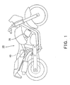
- Fig. 1 is a right side view showing a configuration of a vehicle according to an embodiment of the invention.
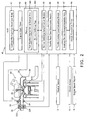
- Fig. 2 is a block diagram showing an example of a configuration of a combustion controlling apparatus of an internal-combustion engine mounted on the vehicle shown in Fig. 1.
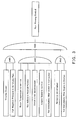
- Fig. 3 is a chart showing a fuel-injection thinning control start logic by the combustion controlling apparatus shown in Fig. 2.
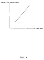
- Fig. 4 is a graph showing an example of the number of pauses of a fuel-injection per one fuel-injection cycle corresponding to an engine speed by the combustion controlling apparatus shown in Fig. 2.
- Fig. 5 is a graph showing an example of the number of pauses of the fuel-injection per one fuel-injection cycle corresponding to a blow-back rate of burned fuel gas (internal Exhaust Gas Return or EGR) by the combustion controlling apparatus shown in Fig. 2.
- EGR Exhaust Gas Return
- Fig. 6 is a graph showing an example of the number of pauses of the fuel-injection per one fuel-injection cycle corresponding to a negative pressure in an air-intake pipe by the combustion controlling apparatus shown in Fig. 2.
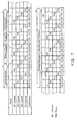
- Fig. 7 is a chart showing an example of fuel-injection interval setting at the start of the fuel-injection thinning control, stored in a fuel-injection interval setting storage area of the combustion controlling apparatus shown in Fig. 2.
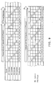
- Fig. 8 is a chart showing another example of the fuel-injection interval setting at the start of the fuel-injection thinning control, stored in the fuel-injection interval setting storage area of the combustion controlling apparatus shown in Fig. 2.
- Fig. 9 is a chart showing still another example of the fuel-injection interval setting at the start of the fuel-injection thinning control, stored in the fuel-injection interval setting storage area of the combustion controlling apparatus shown in Fig. 2.
- Fig. 10 is a chart showing a fuel-injection time at the start of the fuel-injection thinning control by the combustion controlling apparatus shown in Fig. 2, as an injector voltage command value.
- Fig. 11 shows a graph showing an example of corrected fuel-injection time ( ⁇ T) corresponding to the engine speed by the combustion controlling apparatus shown in Fig. 2.
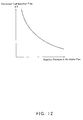
- Fig. 12 shows a graph showing an example of the corrected fuel-injection time ( ⁇ T) corresponding to the negative pressure in the air-intake pipe by the combustion controlling apparatus shown in Fig. 2.
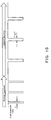
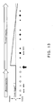
- Fig. 13 is a chart showing an example of an ignition timing at the start of the fuel-injection thinning control by the combustion controlling apparatus shown in Fig. 2, as a crank angle.
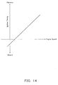
- Fig. 14 is a graph showing an example of the ignition timing (crank angle) corresponding to the engine speed by the combustion controlling apparatus shown in Fig. 2.
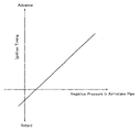
- Fig. 15 is a graph showing an example of the ignition timing (crank angle) corresponding to the negative pressure in the air-intake pipe by the combustion controlling apparatus shown in Fig. 2.
- Fig. 16 is a chart showing a terminating logic of the fuel-injection thinning control by the combustion controlling apparatus shown in Fig. 2.
- Fig. 17 is a chart showing an example (immediate resume) of the fuel-injection interval setting at the termination of the fuel-injection thinning control stored in the fuel-injection interval setting storage area of the combustion controlling apparatus shown in Fig. 2.
- Fig. 18 is a chart showing another example (normal resume) of fuel-injection interval setting at the termination of the fuel-injection thinning control, stored in the fuel-injection interval setting storage area of the combustion controlling apparatus shown in Fig. 2.
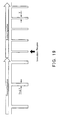
- Fig. 19 is a chart showing the fuel-injection time at the time of the immediate resume shown in Fig. 17, as an injector voltage command value.
- Fig. 20 is a chart showing the fuel-injection time at the time of a normal resume shown in Fig. 18, as the injector voltage command value.
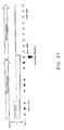
- Fig. 21 is a chart showing the ignition timing at the time of the immediate resume shown in Fig. 17, as the crank angle.
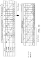
- Fig. 22 is a chart showing the ignition timing at the time of the normal resume shown in Fig. 18, as the crank angle.
- a vehicle 10 according to an embodiment of the present invention shown in Fig. 1 is a typical motorcycle, the vehicle 10 may be any other type of vehicle.
- the vehicle 10 in the form of the motorcycle typically includes an ECU (Electronic Control Unit) 40 that carries out an electronic control of a four-cycle engine 20 as the internal-combustion engine.
- ECU Electronic Control Unit
- the engine 20 includes a throttle body 22 in an air-intake passage 21, and a fuel injector 23 provided downstream of the throttle body 22 in the air-intake passage 21, while it includes a catalyst 26 in an exhaust passage 25.
- the throttle body 22 is a typical throttle body, and includes a throttle valve 223 provided so as to cross the air-intake passage 21 that passes through inside the throttle body 22, and a throttle opening sensor 224 for detecting an opening of the throttle valve 223.
- the throttle opening detected by the throttle opening sensor 224 is transmitted to the ECU 40 that is connected with the throttle opening sensor 224.
- An air-intake pressure sensor 24 is provided downstream of the throttle body 22 in the air-intake passage 21, for detecting a pressure of this section in the air-intake passage 21.
- cylinders of the engine 20 are provided with a water temperature sensor 27 for detecting a temperature of an engine coolant that flows through a water jacket inside a wall of the cylinders.
- the water temperature detected by the water temperature sensor 27 is transmitted to the ECU 40 that is connected with the water temperature sensor 27.
- the ECU 40 is connected with the throttle opening sensor 224, the air-intake pressure sensor 24, and the water temperature sensor 27, as described above, and acquires information detected by these sensors.
- the ECU 40 is also connected with a neutral sensor 12, a clutch sensor 13, and an engine speed sensor 14.
- the neutral sensor 12 detects whether a transmission device or gears (not shown) of the vehicle 10 (refer to Fig. 1) is shifted in a neutral position.
- the clutch sensor 13 detects connection/disconnection of a clutch (not shown) that connects/disconnects a driving-force transmitting path of the vehicle 10 (refer to Fig. 1).
- the engine speed sensor 14 detects an engine speed of the engine 20. Each of these sensors transmits the detected information to the ECU 40, respectively.
- the ECU 40 refers to information (a fuel-injection interval setting, etc.) stored in a fuel-injection interval setting storage area 491 (described later) based on the information from these sensors.
- the ECU 40 controls a fuel-injection and ignition by transmitting an instruction to a fuel injector 23 and a spark plug 28 of the engine 20, respectively.
- the ECU 40 is mainly configured to control the fuel-injection, as described hereinafter.
- the ECU 40 includes a memory 49, as well as an immediately-after-engine-start determination module 41, an engine-start timer 42, and a re-run inhibiting determination module 43.
- the memory 49 is provided with a storage area for a re-run inhibiting flag 492 and the fuel-injection interval setting storage area 491 described above.
- the ECU 40 detects a slowdown of the vehicle 10 (refer to Fig. 1), and when the slowdown is detected, the ECU 40 carries out a thinning control of fuel-injection of the engine 20 according to the setting information stored in the fuel-injection interval setting storage area 491.
- this fuel-injection thinning control will be explained in more detail.
- the ECU 40 is configured so that it determines the vehicle 10 (refer to Fig. 1) is in the slowdown, when a driver operates the throttle valve 223 to a mostly closed state (that is, herein referred to as a "throttle-closing operation") using a throttle control (not illustrated), and thus, when the air-intake pressure sensor 24 disposed downstream of the throttle valve 223 in the air-intake passage detects a high negative pressure state inside the air-intake passage 21, for example, a pressure higher than approximately 300 mmHg (that is, "a high negative pressure in the air-intake pipe").
- the ECU 40 may be configured so that it does not carry out the fuel-injection thinning control until all of the following conditions are satisfied: as further shown in Fig.
- the water temperature of the engine 20 is not low (for example, approximately 60 degrees C or higher); the gears (not shown) are not shifted in the neutral position; the clutch is not disconnected; the engine speed is not low (for example, approximately 1500 rpm or higher); the clutch is not immediately after it is connected (for example, after approximately 200 milliseconds or more from connecting the clutch); the fuel-injection thinning control is not in the re-run status (described later); and the engine is not immediately after its start (for example, approximately 12 seconds or more from the engine start). This is because, if all of these seven conditions are not satisfied, an operational state of the engine 20 is unstable. Thus, if the fuel-injection thinning control is started in the operational state, there is a possibility of a stall of the engine 20.
- the ECU 40 may determine that the water temperature of the engine 20 is not low based on the information from the water temperature sensor 27, that the transmission device is not shifted in the neutral position based on the information from the neutral sensor 12, that the clutch is not disconnected based on the information from the clutch sensor 13, and that the engine speed is not low based on the information from the engine speed sensor 14, for example.
- the clutch is not immediately after it is connected may be determined by providing a clutch connection timer 46 (refer to Fig. 2) to the ECU 40.
- the clutch connection timer 46 measures a time from the clutch being connected based on the information from the clutch sensor 13. This determination is made by the ECU 40 so that the immediately-after-clutch-connected determination module 47 (refer to Fig. 2) refers to the clutch connection timer 46, and determines whether the measured time is less than a predetermined time (for example, less than approximately 200 milliseconds).
- That the fuel-injection thinning control is not in the re-run status may be determined by providing a storage area for the re-run inhibiting flag 492 (refer to Fig. 2) in the memory 49.
- the re-run inhibiting flag 492 stays ON in the storage area for a predetermined period of time (for example, approximately 200 milliseconds) after the last fuel-injection thinning control is terminated. This flag is put down after the lapse of the predetermined time.
- This determination is made by the ECU 40 so that the re-run inhibiting determination module 43 (refer to Fig. 2) refers the re-run inhibiting flag 492, and determines that it is not in the re-run status when the flag is OFF.
- Permitting re-running the control immediately after the termination of the injection thinning causes an alternation of ON and OFF of the control, unintentional unstability of the operational state of the engine, or a possibility of a passenger feeling the torque variation.
- That the engine 20 is not immediately after its start may be determined by providing an engine-start timer 42 (refer to Fig. 2) to the ECU 40.
- the engine-start timer 42 measures a time from the start of the engine 20. This determination is made by the ECU 40 so that the immediately-after-engine-start determination module 41 (refer to Fig. 2) refers to the engine-start timer 42, and determines whether the measured time is less than a predetermined time (for example, less than approximately 12 seconds).
- the ECU 40 is configured to carry out the fuel-injection thinning control when all the nine conditions shown in Fig. 3 are satisfied.
- the fuel-injection thinning control is terminated if any one of the conditions is not satisfied.
- the number of thinning that is, the number of continuous fuel-injection pauses for the entire engine 20, or "the number of fuel-injection pauses", as shown in Figs. 4-6, is configured to be approximately proportional to the engine speed, the blow-back rate of burned fuel gas (internal EGR) or the negative pressure in the air-intake pipe.
- Such proportionality may be stored in the fuel-injection interval setting storage area 491 of the memory 49, and may be configured to be available for the ECU 40, for example.
- "the number of fuel-injection pauses" is not limited to such proportional relationship.
- the fuel-injection thinning control in this embodiment has been configured so that only the fuel-injection by the fuel injector 23 is thinned
- the ignition by the spark plug 28 may also be thinned in addition to this fuel-injection.
- One example of the setting information stored in the fuel-injection interval setting storage area 491 may be in a form of a map, as shown in Figs. 7 and 8.
- This map shows an example for the engine 20 of four-cylinder, and similar principle may be applicable to other number of cylinders.
- it is configured so that the ignition is always carried out in each of the cylinders and, here, only the fuel-injection is controlled to be thinned.
- the ignition timing is controlled auxiliary in this embodiment, "thinning" of the ignition is not carried out. Therefore, in this embodiment, that combustion is or is not carried out can be determined by an existence of the fuel-injection.
- Figs. 7 and 8 that combustion is carried out is indicated by "Y", and the combustion is not carried out is indicated by "N", respectively.
- the number of fuel-injection pauses is even number when the engine 20 is of even number of cylinders.
- the fuel-injection may be carried out once after pausing the fuel-injection four times (i.e., one injection and four pauses), or as shown in Fig. 8, the fuel-injection may be carried out once after pausing the fuel-injection six times (i.e., one injection and six pauses).
- Fig. 7 an example in which the normal fuel-injection is carried out up to the middle of the second cycle is shown. Up to this point, the fuel-injection is carried out one by one from the first (#1), second (#2), fourth (#4), and third (#3) cylinders, and combustion takes place in all of the cylinders. In the second cycle, after carrying out the fuel-injection into the first cylinder and the second cylinder, it shifts to the thinned fuel-injection of one injection and four pauses.
- Fuel-injection is paused in the fourth, third, first, and second cylinders for the total of four times and, then, fuel-injection is carried out once in the fourth cylinder and, then, pausing of fuel-injecyion is repeated in the third, first, second, and fourth cylinders for the total of four times.
- FIG. 8 another example in which the normal fuel-injection is carried out up to the second cycle is shown.
- fuel-injection is carried out one by one from the first (#1), second (#2), fourth (#4), and third (#3) cylinders, and combustion takes place in all of the cylinders.
- the third cycle it shifts to the thinned fuel-injection of one injection and six pauses, and fuel-injection is paused in the first, second, fourth, third, first, and second cylinders for the total of six times and, then, fuel-injection is carried out once in the fourth cylinder and, then, pausing of fuel-injection is repeated in the third, first, second, fourth, third, and first cylinders for the total of six times.
- the number of fuel-injection pauses may be fixed to a number corresponding to the engine speed, the blow-back rate of burned fuel gas (internal EGR), or the negative pressure in the air-intake pipe at the start of the fuel-injection thinning control.
- the number may be reduced in steps or gradually reduced, following the relationship as shown in Figs. 4-6, according to the engine speed, the blow-back rate of burned fuel gas (internal EGR), or the negative pressure in the air-intake pipe which decrease as the slowdown of the vehicle.
- Shown in Fig. 9 is an example in which thinning of fuel-injection of one injection and four pauses is carried out up to the middle of the fourth cycle, and, then, it shifts to thinning of fuel-injection of one injection and two pauses.
- the cylinders i.e., combustion chambers
- an amount of oxygen in each of the cylinders increases.
- an injection command value i.e., a fuel-injection time
- an injection instruction value during the thinned fuel-injection is set as a time T+ ⁇ T.
- a corrected amount of the injection command value during the normal fuel-injection i.e., a corrected fuel-injection time
- ⁇ T is, as shown in Figs. 11 or 12, approximately inversely proportional to the engine speed or the negative pressure in the air-intake pipe. This is because the airscavenging tends to be stimulated to increase the excessive oxygen when the engine speed or the negative pressure in the air-intake pipe is lower. Therefore, in Fig. 10, although the ⁇ T has been indicated as being fixed during the thinned fuel-injection, it is also possible to increase in steps or gradually increase following the decrease in the engine speed or the negative pressure in the air-intake pipe.
- the corrected fuel-injection time ⁇ T may be set as approximately +300 microseconds when the engine speed is at approximately 8000 rpm, or as approximately +1000 microseconds when the engine speed is at approximately 3000 rpm, and so forth.
- a torque by which the engine 20 generates per combustion may be large even if the fuel-injection amount is corrected as described above, and, thus, the passenger may be able to physically recognize the thinning. This may be what is called "cragged" feeling.
- Fig. 13 white arrows in the transverse direction indicate the normal fuel-injection period and the thinned fuel-injection period.
- a white circle indicates fuel-injection during the normal fuel-injection
- a white star indicates ignition during the normal fuel-injection
- a black circle indicates fuel-injection during the thinned fuel-injection
- a black star indicates ignition during the thinned fuel-injection, respectively.
- the ignition timing is approximately proportional to the engine speed or the negative pressure in the air-intake pipe, as shown in Figs. 13 or 14.
- the ignition timing is approximately +10 degrees CA (crank angle) when the engine speed is approximately at 8000 rpm, and is approximately -5 degrees CA when the engine speed is approximately at 2000 rpm.
- the ignition timing is once advanced by a predetermined amount (same level as the above) bacause the torque of the engine 20 is hard to increase due to the thinned fuel-injection at the start of the thinning, and, then, the ignition timing is gradually retarded in order to suppress the torque corresponding to the engine speed that decreases as the vehicle slows down.
- a predetermined amount such as the above
- the ignition timing may be gradually retarded depending on an operational state of the vehicle.
- ignition at the time indicated by a black arrow is carried out with an ignition timing that is as the same as that of the normal fuel-injection although it has already been shifted into the thinned fuel-injection. This shows that ignition is carried out with the normal ignition timing even if it is shifted to the thinned fuel-injection when an amount of unburned fuel that is injected is the amount for the normal fuel-injection.
- a resume operation from the fuel-injection thinning control to the normal fuel-injection control will be explained.
- the resume operation is carried out when any one of the conditions shown in Fig. 3 is not satisfied.
- it is resumed to the normal fuel-injection control immediately (Immediate Resume) since a large engine torque is needed.
- the number of fuel-injection pauses is gradually reduced, finally to zero (Normal Resume).
- the ECU 40 is configured so that it carries out the immediate resume when the throttle valve 223 is rapidly opened (that is, Rapid Throttle Open) by the driver operating the throttle control (not illustrated) at a gear shift, or when the clutch is immediately after it is connected (i.e., Immediately After Clutch is Connected), or when transmission device is shifted into the neutral position (i.e., Shifted into Neutral Position), or otherwise, it carries out the normal resume.
- the rapid throttle open may be determined by the throttle valve 223 being opened faster than a predetermined opening rate (e.g., approximately +160 degrees per second or faster), for example.
- a predetermined opening rate e.g., approximately +160 degrees per second or faster
- the throttle opening speed calculating module 44 calculates an opening rate based on the throttle opening transmitted from the throttle opening sensor 224. By determining whether the opening rate exceeds the predetermined rate by the throttle rapidly-open determination module 45, the ECU 40 determines the rapid throttle open.
- That immediately after the clutch is connected may be determined by, for example, a time being within a predetermined time period (e.g., less than approximately 200 milliseconds) after the clutch is connected. Specifically, as shown in Fig. 2, the clutch connection timer 46 starts a time count upon the information indicating the clutch connection transmitted from the clutch sensor 13. This determination is made by the ECU 40 so that the immediately-after-clutch-connected determination module 47 determines whether the time count does not exceed the predetermined time period.
- a predetermined time period e.g., less than approximately 200 milliseconds
- Fig. 17 shows an example of the immediate resume.
- the thinned fuel-injection one injection and four pauses
- the thinned fuel-injection is carried out up to the middle of the fourth cycle.
- the following fourth cylinder is paused.
- the fourth cylinder is not paused, and pauses of all of the cylinders are terminated immediately to resume the normal fuel-injection.
- Fig. 18 shows an example of the normal resume.
- the thinned fuel-injection one injection and four pauses
- the pause of the second cylinder in this fourth cycle at the time of a black arrow shown in Fig. 18
- it does not resume immediately, but after completing four fuel-injection pauses (one pause for each of the cylinders)
- each of the cylinders is resumed one by one, and finally, it is resumed to the normal fuel-injection.
- the corrected amount of fuel-injection and the corrected ignition timing as described above are also resumed to the original condition in the normal fuel-injection.
- the injection command value is immediately resumed from T+ ⁇ T to T as shown in Fig. 19, by a completely reversed operation with respect to the transition from the normal fuel-injection to the thinned fuel-injection as explained in Fig. 10.
- the normal resume takes place, as shown in Fig. 20, even after transition to the normal fuel-injection, the first fuel-injection amount is maintained to that of the fuel-injection amount of the thinned fuel-injection immediately before that.
- the same ignition timing for the thinned fuel-injection is used (indicated by "a black star”).
- the same ignition timing as that of the thinned fuel-injection is used (by a completely reversed operation with respect to that of the thinned fuel-injection explained in Fig. 13).
- the ignition timing is gradually retarded in this embodimetn in order to suppress the torque corresponding to the engine speed or the negative pressure in the air-intake pipe that decrease as the slowdown of the vehicle during the thinned fuel-injection as shown in Fig. 13, if the time period of the thinned fuel-injection is sufficently long, the ignition timing is corrected to the retard side as shown in Fig. 21. The transition to the normal fuel-injection is carried out by resuming the correction of the ignition timing to 0 degrees.
- the ignition timing upon the normal resume as shown in Fig. 22, the same ignition timing correction is used as that of the thinned fuel-injection, although the ignition at the time shown by a black arrow has already been shifted to the normal fuel-injection. This is to synchronize the fuel-injection amount and the ignition timing, as explained in Fig. 21.
Landscapes
- Engineering & Computer Science (AREA)
- Chemical & Material Sciences (AREA)
- Combustion & Propulsion (AREA)
- Mechanical Engineering (AREA)
- General Engineering & Computer Science (AREA)
- Electrical Control Of Air Or Fuel Supplied To Internal-Combustion Engine (AREA)
- Electrical Control Of Ignition Timing (AREA)
- Output Control And Ontrol Of Special Type Engine (AREA)
- Control Of Vehicle Engines Or Engines For Specific Uses (AREA)
- Combined Controls Of Internal Combustion Engines (AREA)
Applications Claiming Priority (1)
| Application Number | Priority Date | Filing Date | Title |
|---|---|---|---|
| JP2005366129A JP4688670B2 (ja) | 2005-12-20 | 2005-12-20 | 内燃機関の燃焼制御装置および車両 |
Publications (2)
| Publication Number | Publication Date |
|---|---|
| EP1801397A2 true EP1801397A2 (fr) | 2007-06-27 |
| EP1801397A3 EP1801397A3 (fr) | 2009-09-02 |
Family
ID=37820561
Family Applications (1)
| Application Number | Title | Priority Date | Filing Date |
|---|---|---|---|
| EP06256484A Withdrawn EP1801397A3 (fr) | 2005-12-20 | 2006-12-20 | Procédé et dispositif de contrôle de combustion d'un moteur à combustion interne, et véhicule |
Country Status (3)
| Country | Link |
|---|---|
| US (1) | US7475677B2 (fr) |
| EP (1) | EP1801397A3 (fr) |
| JP (1) | JP4688670B2 (fr) |
Cited By (1)
| Publication number | Priority date | Publication date | Assignee | Title |
|---|---|---|---|---|
| WO2011039767A3 (fr) * | 2009-09-30 | 2011-05-26 | M/S.Tvs Motor Company Limited | Système d'amortissement du couple moteur |
Families Citing this family (7)
| Publication number | Priority date | Publication date | Assignee | Title |
|---|---|---|---|---|
| CA2613241A1 (fr) | 2005-06-21 | 2007-01-04 | Cardiomems, Inc. | Procede de fabrication de capteur sans fil implantable pour la mesure de pression in vivo |
| JP5011246B2 (ja) * | 2008-09-22 | 2012-08-29 | 川崎重工業株式会社 | 車両及び燃料カット制御方法 |
| JP4957692B2 (ja) * | 2008-09-26 | 2012-06-20 | トヨタ自動車株式会社 | 内燃機関の制御装置 |
| CN103069140B (zh) * | 2010-08-17 | 2016-02-10 | 沃尔沃建造设备有限公司 | 用于防止水分流入的发动机保护装置 |
| JP6487791B2 (ja) * | 2015-06-25 | 2019-03-20 | 株式会社Soken | 内燃機関の制御装置 |
| JP6327263B2 (ja) * | 2016-02-24 | 2018-05-23 | トヨタ自動車株式会社 | 内燃機関の制御装置 |
| CA3156219C (fr) * | 2021-04-23 | 2026-03-17 | Bombardier Recreational Products Inc. | Methode de commande du freinage moteur dans un vehicule |
Family Cites Families (31)
| Publication number | Priority date | Publication date | Assignee | Title |
|---|---|---|---|---|
| JPS5654933A (en) * | 1979-10-12 | 1981-05-15 | Nissan Motor Co Ltd | Fuel cut device |
| JPS58206835A (ja) * | 1982-05-28 | 1983-12-02 | Honda Motor Co Ltd | 内燃エンジンの減速時燃料供給制御方法 |
| JPS6213747A (ja) * | 1985-07-11 | 1987-01-22 | Nissan Motor Co Ltd | 内燃機関の燃料供給遮断装置 |
| JPS6218657U (fr) * | 1985-07-17 | 1987-02-04 | ||
| JPS6187940A (ja) * | 1985-10-09 | 1986-05-06 | Hitachi Ltd | 自動車用燃料供給装置 |
| JP2507563B2 (ja) * | 1988-11-10 | 1996-06-12 | 日産自動車株式会社 | 交通渋滞認識装置 |
| JP2843380B2 (ja) * | 1989-10-18 | 1999-01-06 | ヤマハ発動機株式会社 | クランク室予圧式・燃料噴射式多気筒2サイクルエンジン |
| JP2779693B2 (ja) * | 1990-06-25 | 1998-07-23 | 本田技研工業株式会社 | クランクケース吸入方式の2サイクルエンジンの燃料噴射装置 |
| JPH04191438A (ja) * | 1990-11-26 | 1992-07-09 | Suzuki Motor Corp | 減速時回転数制御装置 |
| JPH04194341A (ja) * | 1990-11-27 | 1992-07-14 | Mazda Motor Corp | エンジンの燃料制御装置 |
| JPH05163974A (ja) * | 1991-12-12 | 1993-06-29 | Yamaha Motor Co Ltd | 内燃機関の燃料噴射制御装置 |
| JPH05240095A (ja) * | 1992-02-27 | 1993-09-17 | Suzuki Motor Corp | エンジンの燃料噴射制御装置 |
| JP3284597B2 (ja) * | 1992-08-18 | 2002-05-20 | 株式会社デンソー | 内燃機関の出力制御方法 |
| JP2692530B2 (ja) * | 1992-09-02 | 1997-12-17 | トヨタ自動車株式会社 | 内燃機関 |
| JPH06117303A (ja) * | 1992-10-05 | 1994-04-26 | Honda Motor Co Ltd | 内燃エンジンの制御装置 |
| JPH06288274A (ja) * | 1993-03-31 | 1994-10-11 | Daihatsu Motor Co Ltd | 内燃機関の出力制御方法 |
| US5575266A (en) * | 1993-08-31 | 1996-11-19 | Yamaha Hatsudoki Kabushiki Kaisha | Method of operating gaseous fueled engine |
| JPH0771301A (ja) * | 1993-08-31 | 1995-03-14 | Suzuki Motor Corp | アイドル回転数制御のフェイルセーフ装置 |
| JPH094500A (ja) * | 1995-06-22 | 1997-01-07 | Fuji Heavy Ind Ltd | 2サイクル筒内噴射エンジンの制御装置 |
| JP3223791B2 (ja) * | 1996-04-10 | 2001-10-29 | トヨタ自動車株式会社 | 内燃機関の燃料供給装置 |
| JP3209141B2 (ja) * | 1997-04-25 | 2001-09-17 | トヨタ自動車株式会社 | 可変バルブタイミング制御装置 |
| JP3405163B2 (ja) * | 1997-12-17 | 2003-05-12 | トヨタ自動車株式会社 | 内燃機関の燃料噴射量制御装置 |
| JP4326611B2 (ja) * | 1998-10-19 | 2009-09-09 | 日産自動車株式会社 | 直噴ガソリンエンジンの燃料噴射制御装置 |
| JP2001020788A (ja) * | 1999-07-08 | 2001-01-23 | Denso Corp | 内燃機関の減速制御装置 |
| JP2001115872A (ja) * | 1999-10-15 | 2001-04-24 | Mikuni Corp | 2サイクルエンジンの燃料噴射装置の制御方法 |
| DE10135077A1 (de) * | 2001-07-19 | 2003-02-06 | Bosch Gmbh Robert | Verfahren und Vorrichtung zum Betreiben eines Antriebsmotors eines Fahrzeugs |
| JP2003120352A (ja) * | 2001-10-16 | 2003-04-23 | Aisan Ind Co Ltd | エンジンの燃料切換方法とその装置 |
| JP2004116400A (ja) * | 2002-09-26 | 2004-04-15 | Toyota Motor Corp | 内燃機関の制御装置 |
| EP1557931A4 (fr) * | 2002-10-28 | 2010-11-17 | Toyota Motor Co Ltd | Moteur-generateur |
| JP2004293351A (ja) * | 2003-03-26 | 2004-10-21 | Hitachi Ltd | エンジンの燃料カット制御方法 |
| JP2005256664A (ja) * | 2004-03-10 | 2005-09-22 | Toyota Motor Corp | 内燃機関の出力制御装置 |
-
2005
- 2005-12-20 JP JP2005366129A patent/JP4688670B2/ja not_active Expired - Fee Related
-
2006
- 2006-12-19 US US11/642,996 patent/US7475677B2/en not_active Expired - Fee Related
- 2006-12-20 EP EP06256484A patent/EP1801397A3/fr not_active Withdrawn
Cited By (1)
| Publication number | Priority date | Publication date | Assignee | Title |
|---|---|---|---|---|
| WO2011039767A3 (fr) * | 2009-09-30 | 2011-05-26 | M/S.Tvs Motor Company Limited | Système d'amortissement du couple moteur |
Also Published As
| Publication number | Publication date |
|---|---|
| EP1801397A3 (fr) | 2009-09-02 |
| JP2007170222A (ja) | 2007-07-05 |
| JP4688670B2 (ja) | 2011-05-25 |
| US20070144494A1 (en) | 2007-06-28 |
| US7475677B2 (en) | 2009-01-13 |
Similar Documents
| Publication | Publication Date | Title |
|---|---|---|
| US7661403B2 (en) | Start controller for internal combustion engine | |
| EP2420663B1 (fr) | Dispositif de commande de démarrage/arrêt automatique pour moteur à combustion interne | |
| EP1403512B1 (fr) | Système de démarrage pour moteur à combustion interne | |
| US6907871B2 (en) | Ignition timing control system and method for variable-cylinder internal combustion engine as well as engine control unit | |
| KR100342840B1 (ko) | 내연기관의 밸브타이밍 제어장치 | |
| US8838368B2 (en) | Device and method for controlling timing at which ignition is stopped when internal combustion engine becomes stopped | |
| JP4811304B2 (ja) | 車両用エンジンの自動停止装置 | |
| EP2295773B1 (fr) | Procédé de contrôle, produit de programme informatique, dispositif de contrôle pour moteur et moteur | |
| JP5360500B2 (ja) | エンジン自動停止始動制御装置 | |
| EP1801397A2 (fr) | Procédé et dispositif de contrôle de combustion d'un moteur à combustion interne, et véhicule | |
| US6598588B2 (en) | Controlling of ignition timing of an internal combustion engine | |
| JP3721775B2 (ja) | 筒内噴射式エンジンの始動制御装置 | |
| JP3769928B2 (ja) | 自動車用エンジンの制御装置 | |
| JP2006194143A (ja) | エンジンの制御装置 | |
| WO1994011632A1 (fr) | Dispositif anticliquetis destine a un moteur a mecanisme de distribution variable | |
| JP2012136980A (ja) | エンジン回転停止制御装置 | |
| JP2008286167A (ja) | 多気筒内燃機関の制御装置 | |
| JP4325477B2 (ja) | エンジンの始動装置 | |
| JP2004116420A (ja) | エンジンの点火時期制御装置 | |
| JP4661747B2 (ja) | エンジンの停止制御装置 | |
| JP4269503B2 (ja) | 希薄燃焼エンジンの制御装置 | |
| JP4200937B2 (ja) | エンジンの始動装置 | |
| JP4365230B2 (ja) | 内燃機関運転制御装置 | |
| JP2007056772A (ja) | 圧縮着火内燃機関の制御装置 | |
| JP2004324496A (ja) | 内燃機関の制御装置 |
Legal Events
| Date | Code | Title | Description |
|---|---|---|---|
| PUAI | Public reference made under article 153(3) epc to a published international application that has entered the european phase |
Free format text: ORIGINAL CODE: 0009012 |
|
| AK | Designated contracting states |
Kind code of ref document: A2 Designated state(s): AT BE BG CH CY CZ DE DK EE ES FI FR GB GR HU IE IS IT LI LT LU LV MC NL PL PT RO SE SI SK TR |
|
| AX | Request for extension of the european patent |
Extension state: AL BA HR MK YU |
|
| PUAL | Search report despatched |
Free format text: ORIGINAL CODE: 0009013 |
|
| AK | Designated contracting states |
Kind code of ref document: A3 Designated state(s): AT BE BG CH CY CZ DE DK EE ES FI FR GB GR HU IE IS IT LI LT LU LV MC NL PL PT RO SE SI SK TR |
|
| AX | Request for extension of the european patent |
Extension state: AL BA HR MK RS |
|
| RIC1 | Information provided on ipc code assigned before grant |
Ipc: F02D 41/34 20060101ALN20070315BHEP Ipc: F02D 43/04 20060101ALN20070315BHEP Ipc: F02D 41/00 20060101ALI20090727BHEP Ipc: F02D 41/12 20060101AFI20070315BHEP |
|
| 17P | Request for examination filed |
Effective date: 20100302 |
|
| AKX | Designation fees paid |
Designated state(s): IT |
|
| REG | Reference to a national code |
Ref country code: DE Ref legal event code: 8566 |
|
| 17Q | First examination report despatched |
Effective date: 20151013 |
|
| STAA | Information on the status of an ep patent application or granted ep patent |
Free format text: STATUS: THE APPLICATION IS DEEMED TO BE WITHDRAWN |
|
| 18D | Application deemed to be withdrawn |
Effective date: 20160224 |