EP1801432A2 - Pleuel und dessen Herstellungsverfahren - Google Patents
Pleuel und dessen Herstellungsverfahren Download PDFInfo
- Publication number
- EP1801432A2 EP1801432A2 EP06025984A EP06025984A EP1801432A2 EP 1801432 A2 EP1801432 A2 EP 1801432A2 EP 06025984 A EP06025984 A EP 06025984A EP 06025984 A EP06025984 A EP 06025984A EP 1801432 A2 EP1801432 A2 EP 1801432A2
- Authority
- EP
- European Patent Office
- Prior art keywords
- main body
- rod main
- connecting rod
- big end
- rod
- Prior art date
- Legal status (The legal status is an assumption and is not a legal conclusion. Google has not performed a legal analysis and makes no representation as to the accuracy of the status listed.)
- Withdrawn
Links
- 238000000034 method Methods 0.000 title description 25
- 239000007769 metal material Substances 0.000 claims abstract description 42
- 239000000203 mixture Substances 0.000 claims abstract description 14
- 238000003466 welding Methods 0.000 claims description 33
- 239000000463 material Substances 0.000 claims description 27
- 229910001069 Ti alloy Inorganic materials 0.000 claims description 18
- 238000004519 manufacturing process Methods 0.000 claims description 17
- OKTJSMMVPCPJKN-UHFFFAOYSA-N Carbon Chemical compound [C] OKTJSMMVPCPJKN-UHFFFAOYSA-N 0.000 claims description 12
- 229910052799 carbon Inorganic materials 0.000 claims description 12
- 238000002485 combustion reaction Methods 0.000 claims description 11
- 229910000640 Fe alloy Inorganic materials 0.000 claims description 10
- 229910000838 Al alloy Inorganic materials 0.000 claims description 5
- 229910001240 Maraging steel Inorganic materials 0.000 claims description 5
- 229910000861 Mg alloy Inorganic materials 0.000 claims description 5
- 229910000851 Alloy steel Inorganic materials 0.000 claims description 4
- 229910000975 Carbon steel Inorganic materials 0.000 claims description 4
- 229910000677 High-carbon steel Inorganic materials 0.000 claims description 4
- 229910000742 Microalloyed steel Inorganic materials 0.000 claims description 4
- 239000010962 carbon steel Substances 0.000 claims description 4
- 230000005484 gravity Effects 0.000 claims description 4
- 239000013585 weight reducing agent Substances 0.000 description 25
- 229910000831 Steel Inorganic materials 0.000 description 10
- 239000010959 steel Substances 0.000 description 10
- 230000000694 effects Effects 0.000 description 9
- 230000007423 decrease Effects 0.000 description 7
- 239000000956 alloy Substances 0.000 description 5
- 229910045601 alloy Inorganic materials 0.000 description 4
- 230000008901 benefit Effects 0.000 description 4
- 238000010586 diagram Methods 0.000 description 4
- 229910052751 metal Inorganic materials 0.000 description 4
- 239000002184 metal Substances 0.000 description 4
- 230000005540 biological transmission Effects 0.000 description 3
- 230000008859 change Effects 0.000 description 3
- 239000012141 concentrate Substances 0.000 description 3
- 230000003247 decreasing effect Effects 0.000 description 3
- 229910000765 intermetallic Inorganic materials 0.000 description 3
- 230000010355 oscillation Effects 0.000 description 3
- 229910000897 Babbitt (metal) Inorganic materials 0.000 description 2
- 239000010953 base metal Substances 0.000 description 2
- 230000015572 biosynthetic process Effects 0.000 description 2
- 230000000295 complement effect Effects 0.000 description 2
- 238000010276 construction Methods 0.000 description 2
- 238000009826 distribution Methods 0.000 description 2
- 238000010894 electron beam technology Methods 0.000 description 2
- 238000005242 forging Methods 0.000 description 2
- 239000000446 fuel Substances 0.000 description 2
- 230000004927 fusion Effects 0.000 description 2
- 238000010438 heat treatment Methods 0.000 description 2
- 230000002093 peripheral effect Effects 0.000 description 2
- 230000008569 process Effects 0.000 description 2
- 238000004381 surface treatment Methods 0.000 description 2
- 229910052782 aluminium Inorganic materials 0.000 description 1
- 238000005219 brazing Methods 0.000 description 1
- 238000001816 cooling Methods 0.000 description 1
- 230000005489 elastic deformation Effects 0.000 description 1
- 239000002360 explosive Substances 0.000 description 1
- 230000002349 favourable effect Effects 0.000 description 1
- 239000002828 fuel tank Substances 0.000 description 1
- 238000003754 machining Methods 0.000 description 1
- 230000007246 mechanism Effects 0.000 description 1
- 238000002844 melting Methods 0.000 description 1
- 230000008018 melting Effects 0.000 description 1
- 150000002739 metals Chemical class 0.000 description 1
- 238000012986 modification Methods 0.000 description 1
- 230000004048 modification Effects 0.000 description 1
- 238000005096 rolling process Methods 0.000 description 1
Images


Classifications
-
- F—MECHANICAL ENGINEERING; LIGHTING; HEATING; WEAPONS; BLASTING
- F16—ENGINEERING ELEMENTS AND UNITS; GENERAL MEASURES FOR PRODUCING AND MAINTAINING EFFECTIVE FUNCTIONING OF MACHINES OR INSTALLATIONS; THERMAL INSULATION IN GENERAL
- F16C—SHAFTS; FLEXIBLE SHAFTS; ELEMENTS OR CRANKSHAFT MECHANISMS; ROTARY BODIES OTHER THAN GEARING ELEMENTS; BEARINGS
- F16C7/00—Connecting-rods or like links pivoted at both ends; Construction of connecting-rod heads
- F16C7/02—Constructions of connecting-rods with constant length
- F16C7/023—Constructions of connecting-rods with constant length for piston engines, pumps or the like
-
- Y—GENERAL TAGGING OF NEW TECHNOLOGICAL DEVELOPMENTS; GENERAL TAGGING OF CROSS-SECTIONAL TECHNOLOGIES SPANNING OVER SEVERAL SECTIONS OF THE IPC; TECHNICAL SUBJECTS COVERED BY FORMER USPC CROSS-REFERENCE ART COLLECTIONS [XRACs] AND DIGESTS
- Y10—TECHNICAL SUBJECTS COVERED BY FORMER USPC
- Y10T—TECHNICAL SUBJECTS COVERED BY FORMER US CLASSIFICATION
- Y10T74/00—Machine element or mechanism
- Y10T74/21—Elements
- Y10T74/2142—Pitmans and connecting rods
- Y10T74/2159—Section coupled
Definitions
- a connecting rod which is formed by bonding together a plurality of members which are composed of metals of different compositions
- desired mechanical characteristics can be conferred to different regions of the connecting rod.
- a metal material which is light-weight and which has a good fatigue strength may be used for the small end and the rod main body
- a metal material which has a high rigidity and a high elastic modulus may be used for the big end, whereby weight reduction can be achieved while ensuring rigidity of the big end.
- an average carbon content in the big end from a surface to a depth of about 0.2mm is less than about 0.3 mass%, and a distance from the end of the curved section facing the rod main body to the joint is about 3mm or more.
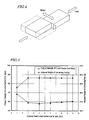
- FIG. 7 is a graph showing a relationship between a distance from a curved section end to a joint, fatigue strength of the curved section end, and adjusted weight of a connecting rod.
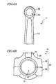
- FIG. 16 is a plan view schematically showing a conventional split-type connecting rod.
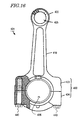
- the big end 30 of the connecting rod 1 has been split into the rod portion 33, which continues to the other end of the rod main body 10; and the cap portion 34, which is coupled to the rod portion 33 via bolts 40 extending through bolt holes 32.
- the rod portion 33 and the cap portion 34 are split by a fracture split technique.
- a fracture split technique is a technique in which the rod portion 33 and the cap portion 34 are integrally formed and thereafter split through brittle fracture. With this technique, through brittle fracture, minute rugged features are formed on fractured surfaces F of the rod portion 33 and the cap portion 34 in a complementary manner.
- the complementary rugged features which are present on the fractured surfaces F of the rod portion 33 and the cap portion 34 enable accurate positioning of the rod portion 33 and the cap portion 34. As the rugged features on the fractured surface F fit one another, the rod portion 33 and the cap portion 34 are more firmly coupled to each other, whereby the rigidity of the entire big end 30 is improved.
- Fatigue strength is not such an important issue for the big end 30 of the connecting rod 1. Rather, the big end 30 is required to have a high rigidity and a high elastic modulus. In the case where the aforementioned fracture split technique is used, the big end 30 should also allow easy brittle fracture. On the other hand, the small end 20 and the rod main body 10 are required to have a high fatigue strength, rather than a high rigidity and a high elastic modulus. In conventional connecting rods, it has been difficult to satisfy all of the aforementioned preferred conditions because the entire connecting rod is integrally formed from the same material.
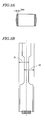
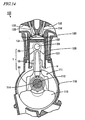
- the cross-sectional area of the connecting rod 1 changes along a direction from the small end 20 to the big end 30 (longitudinal direction Z in FIG. 1), in such a manner that the cross-sectional area undergoes a constant increase in the rod main body 10 from the small end 20 toward the big end 30. Therefore, typically, the end RE of the curved section 30R is defined as a portion where the rate of increase of cross-sectional area changes from the aforementioned constant value (i.e., so as to become greater).
- FIGS. 11A and 11B are diagrams showing a cross section of the rod main body 10 and preferred oscillation directions.
- the big end is also inevitably formed of that same metal material. Since the above metal materials are relatively expensive, use of such an expensive material in the big end will cause an increase in the production cost, even though the big end is not required to have a high specific strength. Moreover, in order to achieve the same level of mechanical strength by using any of the above metal materials, the big end will have to become large, which will again increase the production cost.
Landscapes
- Engineering & Computer Science (AREA)
- General Engineering & Computer Science (AREA)
- Mechanical Engineering (AREA)
- Shafts, Cranks, Connecting Bars, And Related Bearings (AREA)
Applications Claiming Priority (1)
| Application Number | Priority Date | Filing Date | Title |
|---|---|---|---|
| JP2005365746 | 2005-12-20 |
Publications (2)
| Publication Number | Publication Date |
|---|---|
| EP1801432A2 true EP1801432A2 (de) | 2007-06-27 |
| EP1801432A3 EP1801432A3 (de) | 2009-07-22 |
Family
ID=37781825
Family Applications (1)
| Application Number | Title | Priority Date | Filing Date |
|---|---|---|---|
| EP06025984A Withdrawn EP1801432A3 (de) | 2005-12-20 | 2006-12-14 | Pleuel und dessen Herstellungsverfahren |
Country Status (2)
| Country | Link |
|---|---|
| US (1) | US7802493B2 (de) |
| EP (1) | EP1801432A3 (de) |
Families Citing this family (6)
| Publication number | Priority date | Publication date | Assignee | Title |
|---|---|---|---|---|
| US20070261514A1 (en) * | 2006-04-13 | 2007-11-15 | Geiman Timothy E | Multi-material connecting rod |
| US8205332B2 (en) * | 2008-12-08 | 2012-06-26 | Mahle International Gmbh | Method of forming a connecting rod from two dissimiliar materials by providing material blanks of dissimiliar material, joining the material blanks and subsequently forming the connecting rod |
| KR101518945B1 (ko) | 2013-12-11 | 2015-05-12 | 현대자동차 주식회사 | 압축비를 가변시키는 가변 압축비 엔진 |
| US10161439B2 (en) * | 2015-04-16 | 2018-12-25 | Honda Motor Co., Ltd. | Connecting rod and manufacturing method thereof |
| US10578150B2 (en) * | 2018-07-24 | 2020-03-03 | GM Global Technology Operations LLC | Combustion engine connecting rod |
| US10769046B2 (en) * | 2018-11-20 | 2020-09-08 | Rubrik, Inc. | Automated review of source code for style issues |
Citations (4)
| Publication number | Priority date | Publication date | Assignee | Title |
|---|---|---|---|---|
| DE808008C (de) * | 1950-01-28 | 1951-07-09 | Bayerische Motoren Werke Ag | Pleuelstange fuer Brennkraftmaschinen |
| DE3238489A1 (de) * | 1982-10-18 | 1984-04-19 | Fa. Andreas Stihl, 7050 Waiblingen | Pleuelstange |
| DE3339919A1 (de) * | 1983-11-04 | 1985-05-15 | Volkswagenwerk Ag, 3180 Wolfsburg | Gebaute pleuelstange |
| DE19812532A1 (de) * | 1998-03-21 | 1999-09-23 | Audi Ag | Pleuel für eine Hubkolbenmaschine |
Family Cites Families (21)
| Publication number | Priority date | Publication date | Assignee | Title |
|---|---|---|---|---|
| JPS5612080A (en) * | 1979-07-09 | 1981-02-05 | Hitachi Ltd | Full-enclose type motor-driven compressor |
| JPS5887238A (ja) * | 1981-11-19 | 1983-05-25 | Honda Motor Co Ltd | 内燃機関用繊維強化コンロッドの製造方法 |
| JPS60247432A (ja) | 1984-05-23 | 1985-12-07 | Daido Steel Co Ltd | コンロツドの製造方法 |
| BR8501182A (pt) * | 1985-03-08 | 1986-10-14 | Brasil Compressores Sa | Compressor de pistao alternativo para pequenas maquinas de refrigeracao e seu processo de montagem |
| JPS6224019A (ja) * | 1985-07-24 | 1987-02-02 | Yamaha Motor Co Ltd | 板金製コンロツド |
| JPS62288713A (ja) * | 1986-06-03 | 1987-12-15 | Toyota Motor Corp | 焼結コンロツド |
| JPS63199916A (ja) * | 1987-02-16 | 1988-08-18 | Sumitomo Electric Ind Ltd | 複合コンロツド |
| JPH0571526A (ja) * | 1991-09-09 | 1993-03-23 | Nissan Motor Co Ltd | 内燃機関のコネクテイングロツド |
| JPH05196030A (ja) * | 1991-11-14 | 1993-08-06 | Mitsubishi Materials Corp | コネクティングロッド |
| JPH05346112A (ja) * | 1992-06-11 | 1993-12-27 | Mitsubishi Motors Corp | スチール・チタン製コネクチングロッド |
| US5865364A (en) * | 1996-12-24 | 1999-02-02 | United Technologies Corporation | Process for linear friction welding |
| JPH11154435A (ja) | 1997-11-19 | 1999-06-08 | Toshiba Corp | 異種金属材料の接合構造 |
| CA2254349C (en) * | 1997-11-19 | 2003-11-04 | Kabushiki Kaisha Toshiba | Joined structure of dissimilar metallic materials |
| JP3453302B2 (ja) | 1998-05-07 | 2003-10-06 | 三菱重工業株式会社 | TiAl合金部材と構造用鋼材との接合方法及び接合部品 |
| US6244495B1 (en) * | 1998-11-06 | 2001-06-12 | United Technologies Corporation | Gripper |
| JP2000310329A (ja) * | 1999-04-28 | 2000-11-07 | Yamaha Motor Co Ltd | 表面硬化処理したコンロッド |
| JP3413455B2 (ja) | 2000-03-07 | 2003-06-03 | 石川島播磨重工業株式会社 | パイプの製造方法 |
| JP2003126968A (ja) | 2001-10-19 | 2003-05-08 | Ishikawajima Harima Heavy Ind Co Ltd | 直動摩擦溶接方法及び装置 |
| US6688512B2 (en) * | 2001-12-20 | 2004-02-10 | United Technologies Corporation | Apparatus and method for friction welding |
| EP1450056B1 (de) * | 2003-02-19 | 2017-06-07 | Nissan Motor Co., Ltd. | Hochfeste Pleuelstange und Verfahren zu ihrer Herstellung |
| JP2008095831A (ja) * | 2006-10-12 | 2008-04-24 | Toyota Motor Corp | 内燃機関の複合コネクティングロッド |
-
2006
- 2006-12-14 EP EP06025984A patent/EP1801432A3/de not_active Withdrawn
- 2006-12-18 US US11/611,985 patent/US7802493B2/en not_active Expired - Fee Related
Patent Citations (4)
| Publication number | Priority date | Publication date | Assignee | Title |
|---|---|---|---|---|
| DE808008C (de) * | 1950-01-28 | 1951-07-09 | Bayerische Motoren Werke Ag | Pleuelstange fuer Brennkraftmaschinen |
| DE3238489A1 (de) * | 1982-10-18 | 1984-04-19 | Fa. Andreas Stihl, 7050 Waiblingen | Pleuelstange |
| DE3339919A1 (de) * | 1983-11-04 | 1985-05-15 | Volkswagenwerk Ag, 3180 Wolfsburg | Gebaute pleuelstange |
| DE19812532A1 (de) * | 1998-03-21 | 1999-09-23 | Audi Ag | Pleuel für eine Hubkolbenmaschine |
Also Published As
| Publication number | Publication date |
|---|---|
| US7802493B2 (en) | 2010-09-28 |
| US20070151409A1 (en) | 2007-07-05 |
| EP1801432A3 (de) | 2009-07-22 |
Similar Documents
| Publication | Publication Date | Title |
|---|---|---|
| EP3015204B1 (de) | Herstellungsverfahren für titanlegierungs-pleuelstange | |
| US20080271562A1 (en) | Connecting rod for internal combustion engine and method of manufacturing the connecting rod | |
| JPH0520182B2 (de) | ||
| JP4999828B2 (ja) | 破断分割型コンロッド、内燃機関、輸送機器および破断分割型コンロッドの製造方法 | |
| CN100523528C (zh) | 剖分型连杆、发动机以及车辆 | |
| EP1724476B1 (de) | Pleuel mit einem geteilten Pleuelstangenkopf | |
| US7802493B2 (en) | Connecting rod, internal combustion engine, automotive vehicle, and production method for connecting rod | |
| EP1769866B9 (de) | Eisenvorformteil | |
| JP4518922B2 (ja) | 分割型コンロッド、エンジンおよび車両 | |
| JP2006308027A (ja) | コンロッド、内燃機関、自動車両およびコンロッドの製造方法 | |
| JP2007192399A (ja) | コンロッド、内燃機関、自動車両およびコンロッドの製造方法 | |
| JP5916829B1 (ja) | コンロッド、内燃機関、自動車両およびコンロッドの製造方法 | |
| JP4799047B2 (ja) | コンロッドおよびそれを備えた内燃機関ならびに自動車両 | |
| KR100435317B1 (ko) | 열간단조 분할강 커넥팅로드의 제조 방법 | |
| JP2007003000A (ja) | コンロッドおよびそれを備えた内燃機関ならびに自動車両 | |
| EP3015724B1 (de) | Verbindungsstange, brennkraftmaschine, kraftfahrzeug und herstellungsverfahren für verbindungsstange | |
| JP5289130B2 (ja) | 組立クランクシャフトおよびその製造方法 | |
| JPH11107711A (ja) | 中空一体型カムシャフトおよびその製造方法 | |
| KR200290481Y1 (ko) | 캠 샤프트용 엔드 피스 | |
| JP2001191126A (ja) | 突起付き中空軸およびその製造方法 | |
| KR20010094553A (ko) | 캠 샤프트용 엔드 피스 | |
| JP2001214806A (ja) | 内燃機関用ピストンおよびその製造方法 | |
| JPH0542738U (ja) | コンロツド |
Legal Events
| Date | Code | Title | Description |
|---|---|---|---|
| PUAI | Public reference made under article 153(3) epc to a published international application that has entered the european phase |
Free format text: ORIGINAL CODE: 0009012 |
|
| AK | Designated contracting states |
Kind code of ref document: A2 Designated state(s): AT BE BG CH CY CZ DE DK EE ES FI FR GB GR HU IE IS IT LI LT LU LV MC NL PL PT RO SE SI SK TR |
|
| AX | Request for extension of the european patent |
Extension state: AL BA HR MK YU |
|
| PUAL | Search report despatched |
Free format text: ORIGINAL CODE: 0009013 |
|
| AK | Designated contracting states |
Kind code of ref document: A3 Designated state(s): AT BE BG CH CY CZ DE DK EE ES FI FR GB GR HU IE IS IT LI LT LU LV MC NL PL PT RO SE SI SK TR |
|
| AX | Request for extension of the european patent |
Extension state: AL BA HR MK RS |
|
| 17P | Request for examination filed |
Effective date: 20091008 |
|
| AKX | Designation fees paid |
Designated state(s): AT BE BG CH CY CZ DE DK EE ES FI FR GB GR HU IE IS IT LI LT LU LV MC NL PL PT RO SE SI SK TR |
|
| 17Q | First examination report despatched |
Effective date: 20110418 |
|
| STAA | Information on the status of an ep patent application or granted ep patent |
Free format text: STATUS: THE APPLICATION IS DEEMED TO BE WITHDRAWN |
|
| 18D | Application deemed to be withdrawn |
Effective date: 20110830 |