EP1801463A2 - Dispositif pour changer la vitesse pour une boîte de vitesses - Google Patents
Dispositif pour changer la vitesse pour une boîte de vitesses Download PDFInfo
- Publication number
- EP1801463A2 EP1801463A2 EP06024481A EP06024481A EP1801463A2 EP 1801463 A2 EP1801463 A2 EP 1801463A2 EP 06024481 A EP06024481 A EP 06024481A EP 06024481 A EP06024481 A EP 06024481A EP 1801463 A2 EP1801463 A2 EP 1801463A2
- Authority
- EP
- European Patent Office
- Prior art keywords
- shift
- switching
- gate
- positions
- automatic
- Prior art date
- Legal status (The legal status is an assumption and is not a legal conclusion. Google has not performed a legal analysis and makes no representation as to the accuracy of the status listed.)
- Granted
Links
Images



Classifications
-
- F—MECHANICAL ENGINEERING; LIGHTING; HEATING; WEAPONS; BLASTING
- F16—ENGINEERING ELEMENTS AND UNITS; GENERAL MEASURES FOR PRODUCING AND MAINTAINING EFFECTIVE FUNCTIONING OF MACHINES OR INSTALLATIONS; THERMAL INSULATION IN GENERAL
- F16H—GEARING
- F16H59/00—Control inputs to control units of change-speed- or reversing-gearings for conveying rotary motion
- F16H59/02—Selector apparatus
- F16H59/0204—Selector apparatus for automatic transmissions with means for range selection and manual shifting, e.g. range selector with tiptronic
-
- F—MECHANICAL ENGINEERING; LIGHTING; HEATING; WEAPONS; BLASTING
- F16—ENGINEERING ELEMENTS AND UNITS; GENERAL MEASURES FOR PRODUCING AND MAINTAINING EFFECTIVE FUNCTIONING OF MACHINES OR INSTALLATIONS; THERMAL INSULATION IN GENERAL
- F16H—GEARING
- F16H59/00—Control inputs to control units of change-speed- or reversing-gearings for conveying rotary motion
- F16H59/02—Selector apparatus
- F16H2059/0295—Selector apparatus with mechanisms to return lever to neutral or datum position, e.g. by return springs
-
- F—MECHANICAL ENGINEERING; LIGHTING; HEATING; WEAPONS; BLASTING
- F16—ENGINEERING ELEMENTS AND UNITS; GENERAL MEASURES FOR PRODUCING AND MAINTAINING EFFECTIVE FUNCTIONING OF MACHINES OR INSTALLATIONS; THERMAL INSULATION IN GENERAL
- F16H—GEARING
- F16H61/00—Control functions within control units of change-speed- or reversing-gearings for conveying rotary motion ; Control of exclusively fluid gearing, friction gearing, gearings with endless flexible members or other particular types of gearing
- F16H61/22—Locking of the control input devices
-
- F—MECHANICAL ENGINEERING; LIGHTING; HEATING; WEAPONS; BLASTING
- F16—ENGINEERING ELEMENTS AND UNITS; GENERAL MEASURES FOR PRODUCING AND MAINTAINING EFFECTIVE FUNCTIONING OF MACHINES OR INSTALLATIONS; THERMAL INSULATION IN GENERAL
- F16H—GEARING
- F16H63/00—Control outputs from the control unit to change-speed- or reversing-gearings for conveying rotary motion or to other devices than the final output mechanism
- F16H63/40—Control outputs from the control unit to change-speed- or reversing-gearings for conveying rotary motion or to other devices than the final output mechanism comprising signals other than signals for actuating the final output mechanisms
- F16H63/42—Ratio indicator devices
-
- Y—GENERAL TAGGING OF NEW TECHNOLOGICAL DEVELOPMENTS; GENERAL TAGGING OF CROSS-SECTIONAL TECHNOLOGIES SPANNING OVER SEVERAL SECTIONS OF THE IPC; TECHNICAL SUBJECTS COVERED BY FORMER USPC CROSS-REFERENCE ART COLLECTIONS [XRACs] AND DIGESTS
- Y10—TECHNICAL SUBJECTS COVERED BY FORMER USPC
- Y10T—TECHNICAL SUBJECTS COVERED BY FORMER US CLASSIFICATION
- Y10T74/00—Machine element or mechanism
- Y10T74/20—Control lever and linkage systems
- Y10T74/20012—Multiple controlled elements
- Y10T74/20018—Transmission control
- Y10T74/20067—Control convertible between automatic and manual operation
-
- Y—GENERAL TAGGING OF NEW TECHNOLOGICAL DEVELOPMENTS; GENERAL TAGGING OF CROSS-SECTIONAL TECHNOLOGIES SPANNING OVER SEVERAL SECTIONS OF THE IPC; TECHNICAL SUBJECTS COVERED BY FORMER USPC CROSS-REFERENCE ART COLLECTIONS [XRACs] AND DIGESTS
- Y10—TECHNICAL SUBJECTS COVERED BY FORMER USPC
- Y10T—TECHNICAL SUBJECTS COVERED BY FORMER US CLASSIFICATION
- Y10T74/00—Machine element or mechanism
- Y10T74/20—Control lever and linkage systems
- Y10T74/20012—Multiple controlled elements
- Y10T74/20018—Transmission control
- Y10T74/20085—Restriction of shift, gear selection, or gear engagement
Definitions
- the present invention relates to a switching device for an automated or automatic transmission, in particular of a motor vehicle, having the features of the preamble of claim 1.
- Such a transmission is for example from the EP 0 416 227 A1 known and has a shift lever for selecting automatic shift stages and gears of the transmission, which can be converted from a stable starting position into a plurality of immediately adjacent labile shift positions for selecting the automatic shift stages and gears, from which it automatically returns to the starting position. Furthermore, a display is provided which is used to visualize the currently engaged gear and / or the currently activated automatic shift stage.
- the known switching device comprises two shift gates, which intersect in the stable starting position and each have on either side of the stable starting position one of the unstable switching positions.
- a transmission control assigns the starting position and the shift positions to the individual automatic shift stages which can be selected by deflecting or tapping the shift lever into the unstable shift positions.
- the automatic shift stages is also a manual shift stage, in which can be switched by forwards and backwards tapping the shift lever between the individual gears of the transmission.
- the automatic shift stages include a parking position in which a parking brake of the transmission is activated.
- the shift lever is adjustable in a shift gate having four juxtaposed stable shift positions, which are each associated with an automatic shift stage of the transmission.
- the outer stable switching positions which is designed as a manual shift stage
- border three labile switching positions one of which is configured as a forward-switching stage and arranged in the shift gate.
- the other two unstable switch positions are arranged on both sides of the stable manual shift position in a cross track, which the shift gate in the manual shift position crosses.
- the two unstable switching positions of the cross lane are used to upshift and downshift the gears.
- the other stable shift positions of the shift gate are an idle shift stage, a reverse shift stage, and a park shift stage.
- the DE 20 2004 004 151 U1 shows a switching device in which a shift lever in an automatic shift gate for switching between automatic shift stages is adjustable and can be transferred via a cross track in a tap shift gate, in which it is adjustable for switching between gears.
- the shift lever In the tip shift gate, the shift lever has a stable shift position, in which the shift lever automatically returns from all unstable shift positions of the three lanes.
- a shift lever is adjustable in two interconnected via a cross track switching lanes for selecting gears or automatic shift stages.
- the known switching device is monostable and has only a single stable switching position for the shift lever.
- the shift lever is manually deflected from its stable shift position in one or the other shift gate in the respective desired shift position. Subsequently, the lever returns automatically after releasing from any possible deflection position in the stable switching position.
- the present invention is concerned with the problem of providing for a switching device of the type mentioned an improved embodiment, which characterized in particular by easy handling and preferably by a high level of operational reliability.
- the invention is based on the general idea, the shift lever between two stable switching positions, namely the starting position and a rest position, adjustable to design, the shift lever can be transferred only in the starting position in a plurality of immediately adjacent labile switching positions. In this way, the stable rest position can be easily assigned a decoupled from normal driving transmission function.
- the switching device can be particularly easy to use and has increased reliability.
- the rest position is associated with a parking shift stage of the transmission, in which a parking brake of the transmission is activated.
- a parking brake of the transmission is activated.
- a locking button may be provided, which secures the displaced in the rest position shift lever in the rest position in the unactuated state and only in the actuated state, a lead out of the shift lever from the rest position permits.
- said locking button can be designed so that it secures the shifted in the initial position shift lever in the starting position in the actuated state and only in the unactuated state allows an adjustment of the shift lever in the adjacent labile switch positions. This measure also increases the reliability and ease of operation of the transmission, since when transferring the shift lever from the rest position to the starting position, an inadvertent deflection of the shift lever in one of the unstable switching positions is not possible.
- a further increase in comfort and increased reliability can be achieved in that the safety button allows only in the actuated state, a transfer of the shift lever from the starting position to the rest position. This makes it possible to avoid accidental transfer of the shift lever in the rest position during driving.
- a switching device 1 according to the invention comprises a shift lever 2, which is adjustable in a shift gate assembly 3, and a display 4 and a transmission control 5.
- the switching device 1 is used to actuate an automated or automatic transmission 6, preferably a motor vehicle.
- the shift gate assembly 3 which can also be referred to as a real shift gate configuration, comprises a first shift gate 7 and a second shift gate 8 intersecting the first shift gate 7.
- the first shift gate 7 is preferably oriented parallel to the vehicle longitudinal direction in the installed state and will therefore also be referred to as the longitudinal track 7 in the following designated.
- the second shift gate 8 is preferably oriented transversely to the vehicle longitudinal direction and is therefore also referred to below as the cross track 8. Longitudinal lane 7 and cross lane 8 are preferably perpendicular to each other.
- the real shift gate configuration 3 is designed such that it provides a stable starting position 9 and a plurality of unstable shift positions 10 to 13 for the shift lever 2.
- the labile switching positions 10 to 13 are arranged immediately adjacent to the stable starting position 9 and are characterized in that the deflected from the stable starting position 9 in one of the unstable switching positions 10 to 13 shift lever 2 automatically returns to the starting position 9.
- the switching device 1 is provided with corresponding return means.
- the starting position 9 is arranged centrally with respect to the switching positions 10 to 13.
- the shift lever 2 must be deflected from the starting position 9 for transferring into the shift position 10 forward, in the shift position 11 to the rear, in the shift position 12 to the left and in the shift position 13 to the right.
- the left shift position 12 and the right shift position 13 on the cross track 8 on both sides of the Starting position 9 while the front-switching position 10 and the rear-switching position 11 are arranged in the longitudinal axis 7 on both sides of the starting position 9.
- the shift gate assembly 3 comprises a rest position 14 designated as further stable switching position, in which the shift lever 2 from the initial position 9 can be transferred.
- the stable rest position 14 is also arranged in the longitudinal lane 7 and that end. Since there is no further cross track, the shift lever 2 can only be moved out of the rest position 14 in one direction, namely in the direction of the starting position 9.
- stable switching positions are symbolized by double circles, while labile switching positions are represented by single circles.
- the transmission control 5 assigns the stable starting position 9 and the unstable switching positions 10 to 13 automatic shift stages and / or gears of the transmission 6 to.
- an indicated by a double arrow electronic active connection 15 between the transmission control 5 and the shift gate assembly 3 is provided.
- the transmission control 5 is connected by an electronic operative connection 16 with the display 4.
- the display 4 serves to visualize the currently engaged gear and / or the currently activated automatic gear shift stage.
- the display 4 serves here for the visualization of all possible gears and automatic shift stages.
- the transmission 6 comprises, as automatic shift stages, a forward shift stage D, an idle shift stage N and a reverse shift stage R.
- a manual shift stage M is provided here in which, by deflecting the shift lever 2 into downshift positions adjacent thereto, so-called downshift position, characterized by a minus sign (-), and for upshifting, so-called upshift position, characterized by a plus sign (+), the individual gears (1) to (6) of the transmission 6 can be selected.
- the aforementioned shift positions, gears and automatic shift stages are electronically assigned via the transmission control 5 to the starting position 9 and to the adjacent four unstable shift positions 10 to 13.
- the transmission control 5 is on usual manner, for example, coupled via an indicated by a double arrow electronic operative connection 23 to the transmission 6.
- the transmission 6 comprises a parking shift stage P, in which a parking lock of the transmission 6 is activated.
- This parking shift stage P is assigned to the stable rest position 14.
- the park shift stage P of the rest position 14 is not assigned electronically via the transmission control 5, but mechanically.
- a corresponding mechanical operative connection 17 between the rest position 14 and the transmission 6 is symbolized in FIG. 1 by a double arrow.
- This mechanical operative connection 17 is realized for example by a cable.
- the switching device 1 preferably comprises exactly two stable switching positions, namely the starting position 9 and the rest position 14, as well as exactly four labile shift lever positions 10 to 13. About this total of 6 shift positions 9 to 14 all gears and automatic transmission stages of the transmission 6 can be selected.
- the transmission control 5 simulates a virtual shift gate configuration 18, which is visualized to the user via the display 4.
- the virtual shift gate configuration 18 comprises two parallel shift gates, namely an automatic shift gate 19 for selecting the automatic shift stages and a jog shift gate 20 for selecting the gears. Furthermore, a connecting lane 21 is provided, which extends transversely to the two shift gates 19, 20 and connects them together.
- the automatic shift gate 19 a plurality of virtual stable shift gate positions are simulated, to each of which one of the automatic shift stages, here the forward shift stage D, the reverse shift stage R and in between the idle shift stage N, is assigned.
- the jogging lane 20 includes only one virtual stable Shift gate position to which the manual shift stage M is assigned.
- the jog shift gate 20 on both sides of the manual shift stage M additionally includes two virtual labile shift gate positions to which the upshift position (+) and the downshift position (-) are assigned.
- the connection lane 21 is here arranged to virtually connect the manual shift stage M to the forward shift stage D.
- the display 4 visualizes the real stable rest position 14, which is assigned to the parking shift stage P.
- the display 4 preferably visualizes the shiftable forward gears of the transmission 6.
- the respective active automatic shift stage and the respectively engaged gear are symbolized by a ring filling the respective double circle.
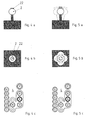
- the shift lever 2 is in the rest position 14. This is assigned to the parking shift stage P, which is signaled on the display 4 by a corresponding emphasis.
- the switching device 1 is additionally equipped with a locking button 22, which is integrated in the embodiment shown here in the shift lever 2 and is formed or arranged on this.
- the fuse button 22 is unconfirmed.
- the safety button 22 is designed so that in its unactuated state of the displaced in the rest position 14 shift lever 2 is secured in the rest position 14 and thus is unadjustable. The parking shift stage P is thus effectively secured.
- the safety key 22 is actuated, eg by depression. In its actuated state, the safety button 22 releases the shift lever 2, so that it can be brought out of the rest position 14.
- the locking button 22 in the rest position 14 ver admiratorym shift lever 2, however, the parking shift stage P and thus the parking brake of the transmission 6 remains active.
- 4a to 4c show the displaced to the starting position 9 shift lever 2 when actuated lock button 22.
- the fuse button 22 is designed so that it secures the shifted in the starting position 9 shift lever 2 in the initial position 9 in the actuated state, and so in that it can not be transferred into the adjacent unstable switching positions 10 to 13.
- the shift lever 2 can be adjusted only between the rest position 14 and the starting position 9.
- the transmission control 5 automatically activates the idle shift stage N when the shift lever 2 is transferred from the rest position 14 into the starting position 9.
- the shift lever 2 can deflect from its initial position 9 in the labile switching positions 10 to 13, but not in the stable rest position 14th
- a further backup in the form of a locking device not shown here may be provided.
- the shift lever 2 may be e.g. only be transferred from the rest position 14 in the starting position 9 when an ignition key is arranged in the ignition, while it is unscrewed from the trigger position and when the driver operates the service brake.
- the idle switching stage N is activated.
- the shift lever 2 can now be moved to the front, back, left and right in the corresponding labile switch positions 10 to 13.
- the transmission controller 5 arranges the deflection of the shift lever 2 in response to the direction of movement of this shift lever deflection movement of the Shift lever 2 in the virtual shift gate configuration 18 in the corresponding direction.
- the operation of the switching device 1 will be explained in more detail with reference to FIGS. 6 to 9 with several examples.
- the shift lever 2 In the initial state, the shift lever 2 is in the real starting position 9 and within the virtual shift gate configuration 18 in the idle shift stage N. According to the virtual automatic shift gate 19, only a deflection of the shift lever 2 in the front-shift position 10 and in the rear Switching position 11 to a switching operation, while deflections to the left and right are ignored.
- additional securing may be provided, such that the transmission control 5 also ignores forward deflection and backward deflection as long as the neutral gear shift N is activated and the service brake of the vehicle is unactuated , This means that when the neutral gear shift stage N is active, switching to another automatic gear shift stage by deflecting the shift lever 2 into one of the unstable shift positions 10 to 13 is only possible when the service brake of the vehicle is actuated.
- the shift lever 2 is deflected forward in the labile front-switching position 10.
- the transmission control 5 causes an activation of the reverse gear R.
- the virtual automatic shift gate 19 of the shift lever 2 is adjusted accordingly, which is shown in FIG. 6b of the display 4 can be removed.
- the transmission control 5 switches from the idle shift stage N to the forward shift stage D.
- the active shift state or the current position of the shift lever 2 within the virtual Wegsenkonfiguration 18 is shown in FIG. 7b again to remove the display 4.
- the forward shift stage D starting from the idle shift stage N, the first transmission gear is automatically engaged, which can also be seen in the display 4.
- the shift lever 2 If the shift lever 2 is located in the virtual automatic shift gate 19 in the forward shift stage D, it can be transferred into the virtual jogging lane 20 via a virtual linkage lane 20, as shown in FIG. 8a, by way of a deflection into the left shift position 12 there in the manual switching stage M, which according to Fig. 8b again the display 4 can be removed.
- the manual shift stage M By activating the manual shift stage M, the currently engaged transmission gear is not changed. In the example, the first gear is thus engaged.
- the shift lever 2 can now be deflected within the virtual tilting lane 20 by pre-tapping and tapping back into the labile forward shift position 10 or the unstable rear shift position 11. This is accompanied by a gradual upshifting and downshifting of the gears. In the example shown in FIG. 9b, 5th gear is engaged.
Landscapes
- Engineering & Computer Science (AREA)
- General Engineering & Computer Science (AREA)
- Mechanical Engineering (AREA)
- Arrangement Or Mounting Of Control Devices For Change-Speed Gearing (AREA)
- Control Of Transmission Device (AREA)
- Arrangement And Mounting Of Devices That Control Transmission Of Motive Force (AREA)
Applications Claiming Priority (1)
| Application Number | Priority Date | Filing Date | Title |
|---|---|---|---|
| DE102005062298A DE102005062298A1 (de) | 2005-12-24 | 2005-12-24 | Schaltvorrichtung für ein Getriebe |
Publications (3)
| Publication Number | Publication Date |
|---|---|
| EP1801463A2 true EP1801463A2 (fr) | 2007-06-27 |
| EP1801463A3 EP1801463A3 (fr) | 2008-06-18 |
| EP1801463B1 EP1801463B1 (fr) | 2013-10-23 |
Family
ID=37890529
Family Applications (1)
| Application Number | Title | Priority Date | Filing Date |
|---|---|---|---|
| EP06024481.1A Not-in-force EP1801463B1 (fr) | 2005-12-24 | 2006-11-25 | Dispositif pour changer la vitesse pour une boîte de vitesses |
Country Status (4)
| Country | Link |
|---|---|
| US (1) | US7878087B2 (fr) |
| EP (1) | EP1801463B1 (fr) |
| JP (1) | JP4747083B2 (fr) |
| DE (1) | DE102005062298A1 (fr) |
Cited By (2)
| Publication number | Priority date | Publication date | Assignee | Title |
|---|---|---|---|---|
| CN102815212A (zh) * | 2011-06-09 | 2012-12-12 | 现代自动车株式会社 | 点火控制类型的汽车杆设备 |
| EP2868948A1 (fr) * | 2013-10-29 | 2015-05-06 | Volvo Car Corporation | Procédé pour changer les vitesses et arrangement de changement de vitesse |
Families Citing this family (13)
| Publication number | Priority date | Publication date | Assignee | Title |
|---|---|---|---|---|
| DE102005062296B3 (de) * | 2005-12-24 | 2007-08-09 | Dr.Ing.H.C. F. Porsche Ag | Getriebeschaltvorrichtung |
| DE102007007667A1 (de) * | 2007-02-13 | 2008-08-14 | Leopold Kostal Gmbh & Co. Kg | Elektrische Schalteinrichtung für ein Kraftfahrzeug |
| DE102007037750B4 (de) * | 2007-08-10 | 2013-03-14 | Bayerische Motoren Werke Aktiengesellschaft | Wählhebel für ein Kraftfahrzeug |
| DE102007047120B4 (de) * | 2007-10-02 | 2013-01-10 | Audi Ag | Schalteinheit für ein insbesondere elektronisch geschaltetes Getriebe eines Kraftfahrzeugs |
| DE102008049935A1 (de) | 2008-10-02 | 2010-04-08 | Dura Automotive Systems Einbeck Gmbh | Verfahren zur Schaltbetätigung eines Automatikgetriebes oder automatischen Schaltgetriebes eines Fahrzeugs und Wählbetätigungsvorrichtung |
| GB0905843D0 (en) * | 2009-04-03 | 2009-05-20 | Bentley Motors Ltd | Selector |
| DE112011100277T5 (de) * | 2010-01-19 | 2012-11-08 | Honda Motor Co., Ltd. | Schaltvorrichtung |
| US20130220055A1 (en) * | 2012-02-28 | 2013-08-29 | Nissan North America, Inc. | Multifunctional integrated shifter |
| US9476501B2 (en) * | 2013-05-21 | 2016-10-25 | GM Global Technology Operations LLC | Gear shifter |
| US9115803B2 (en) * | 2013-08-28 | 2015-08-25 | Ford Global Technologies, Llc | Methods and systems for operating a transmission |
| DE102015102586A1 (de) * | 2015-02-24 | 2016-08-25 | Küster Holding GmbH | Schalteinheit für ein Getriebe eines Kraftfahrzeuges |
| KR102584369B1 (ko) * | 2018-12-11 | 2023-10-04 | 에스엘 주식회사 | 차량용 변속 장치 |
| CN112344007B (zh) * | 2019-08-08 | 2022-04-26 | 广州汽车集团股份有限公司 | 一种单稳态电子换挡机构的换挡方法 |
Citations (4)
| Publication number | Priority date | Publication date | Assignee | Title |
|---|---|---|---|---|
| DE19714495A1 (de) | 1997-04-08 | 1998-10-15 | Bayerische Motoren Werke Ag | Wähleinrichtung mit einer Anzeigeeinrichtung |
| DE10112698A1 (de) | 2001-03-16 | 2002-09-19 | Daimler Chrysler Ag | Schaltvorrichtung für ein Kraftfahrzeuggetriebe |
| DE10206985A1 (de) | 2002-02-20 | 2003-08-21 | Bayerische Motoren Werke Ag | Getriebeschalteinrichtung |
| DE202004004151U1 (de) | 2004-03-17 | 2004-06-03 | Zf Friedrichshafen Ag | Schaltvorrichtung für automatisierte oder automatische Getriebe |
Family Cites Families (17)
| Publication number | Priority date | Publication date | Assignee | Title |
|---|---|---|---|---|
| DE3929268A1 (de) * | 1989-09-02 | 1991-03-07 | Bayerische Motoren Werke Ag | Kraftfahrzeuggetriebe |
| JPH10100723A (ja) | 1996-09-27 | 1998-04-21 | Toyota Motor Corp | 自動変速機の表示装置 |
| DE19714459C2 (de) | 1997-04-08 | 2001-11-29 | Framatome Connectors Int | Steckverbinder mit einer Gehäuseverriegelung |
| DE19737296C2 (de) * | 1997-08-27 | 1999-11-18 | Daimler Chrysler Ag | Selbsttätige Schaltvorrichtung eines Gangwechselgetriebes mit einem Handwählorgan |
| JP3962968B2 (ja) * | 1999-04-12 | 2007-08-22 | スズキ株式会社 | 自動車用変速機のパーキング装置 |
| JP2001280463A (ja) * | 2000-03-31 | 2001-10-10 | Isuzu Motors Ltd | 車両の自動変速装置 |
| JP2002139143A (ja) * | 2000-11-06 | 2002-05-17 | Tokai Rika Co Ltd | 車両用変速機制御装置 |
| DE10208387B4 (de) * | 2001-02-28 | 2014-01-30 | Kabushiki Kaisha Tokai Rika Denki Seisakusho | Gerät zum elektrischen Steuern eines Getriebes eines Fahrzeuges |
| EP2339213B1 (fr) * | 2001-03-02 | 2014-09-03 | Toyota Jidosha Kabushiki Kaisha | Dispositif de changement de vitesse pour une véhicule |
| JP2002276782A (ja) * | 2001-03-16 | 2002-09-25 | Fuji Heavy Ind Ltd | 自動変速機の入力装置 |
| JP4590772B2 (ja) * | 2001-04-12 | 2010-12-01 | トヨタ自動車株式会社 | シフト制御装置 |
| DE10156091A1 (de) * | 2001-10-05 | 2003-07-10 | Zf Lemfoerder Metallwaren Ag | Signalgeber zum Einstellen der Betriebszustände einer selbsttätigen Schaltvorrichtung |
| JP3996380B2 (ja) * | 2001-11-27 | 2007-10-24 | 株式会社東海理化電機製作所 | シフトロック装置 |
| DE10223854A1 (de) * | 2002-05-28 | 2003-12-11 | Zf Lemfoerder Metallwaren Ag | Optische Anzeigevorrichtung einer Wählhebelanordnung |
| DE10326118B4 (de) | 2003-06-06 | 2005-04-14 | ZF Lemförder Metallwaren AG | Schaltvorrichtung zur mechanisch kopplungsfreien Übertragung von Schaltbefehlen an ein automatisches Kraftfahrzeuggetriebe |
| JP2005119394A (ja) * | 2003-10-15 | 2005-05-12 | Atsumi Tec:Kk | 車両用自動変速操作装置 |
| JP4789758B2 (ja) * | 2005-11-25 | 2011-10-12 | 日産自動車株式会社 | Atセレクタカバー |
-
2005
- 2005-12-24 DE DE102005062298A patent/DE102005062298A1/de not_active Ceased
-
2006
- 2006-11-25 EP EP06024481.1A patent/EP1801463B1/fr not_active Not-in-force
- 2006-12-13 JP JP2006335764A patent/JP4747083B2/ja not_active Expired - Fee Related
- 2006-12-26 US US11/645,838 patent/US7878087B2/en not_active Expired - Fee Related
Patent Citations (4)
| Publication number | Priority date | Publication date | Assignee | Title |
|---|---|---|---|---|
| DE19714495A1 (de) | 1997-04-08 | 1998-10-15 | Bayerische Motoren Werke Ag | Wähleinrichtung mit einer Anzeigeeinrichtung |
| DE10112698A1 (de) | 2001-03-16 | 2002-09-19 | Daimler Chrysler Ag | Schaltvorrichtung für ein Kraftfahrzeuggetriebe |
| DE10206985A1 (de) | 2002-02-20 | 2003-08-21 | Bayerische Motoren Werke Ag | Getriebeschalteinrichtung |
| DE202004004151U1 (de) | 2004-03-17 | 2004-06-03 | Zf Friedrichshafen Ag | Schaltvorrichtung für automatisierte oder automatische Getriebe |
Cited By (2)
| Publication number | Priority date | Publication date | Assignee | Title |
|---|---|---|---|---|
| CN102815212A (zh) * | 2011-06-09 | 2012-12-12 | 现代自动车株式会社 | 点火控制类型的汽车杆设备 |
| EP2868948A1 (fr) * | 2013-10-29 | 2015-05-06 | Volvo Car Corporation | Procédé pour changer les vitesses et arrangement de changement de vitesse |
Also Published As
| Publication number | Publication date |
|---|---|
| JP2007168771A (ja) | 2007-07-05 |
| EP1801463B1 (fr) | 2013-10-23 |
| DE102005062298A1 (de) | 2007-06-28 |
| EP1801463A3 (fr) | 2008-06-18 |
| US20070144294A1 (en) | 2007-06-28 |
| US7878087B2 (en) | 2011-02-01 |
| JP4747083B2 (ja) | 2011-08-10 |
Similar Documents
| Publication | Publication Date | Title |
|---|---|---|
| EP1338831B1 (fr) | Dispositif de changement de vitesse pour transmission | |
| EP2049818B1 (fr) | Dispositif de changement de vitesses pour une boîte de vitesses automatisée ou automatique | |
| DE102007010052A1 (de) | Steuer-/Regelvorrichtung für ein Automatikgetriebe | |
| EP1801463B1 (fr) | Dispositif pour changer la vitesse pour une boîte de vitesses | |
| WO2001031232A1 (fr) | Dispositif de commutation pour boite de vitesses automatique de vehicule a commande electronique | |
| DE4332265C1 (de) | Anordnung zum Steuern des Gangwechsels eines selbsttätig schaltenden Gangwechselgetriebes eines Kraftfahrzeuges | |
| EP1616116A1 (fr) | Boite de vitesses multi-etagee pour moteur a combustion interne | |
| WO2008074375A1 (fr) | Elément de commande de commutation pour une boîte de vitesses d'un véhicule automobile avec commutation à commande électronique | |
| EP1549866B1 (fr) | Unite d'entree de rapports de vitesse | |
| DE19850685A1 (de) | Wähleinrichtung für ein automatisches Getriebe eines Kraftfahrzeugs | |
| EP1432934A1 (fr) | Emetteur de signaux concu pour regler les etats de fonctionnement d'un dispositif de commutation automatique | |
| DE102005062296B3 (de) | Getriebeschaltvorrichtung | |
| DE102007047120B4 (de) | Schalteinheit für ein insbesondere elektronisch geschaltetes Getriebe eines Kraftfahrzeugs | |
| EP0616153A2 (fr) | Dispositif de changement de vitesse poir boîte de vitesses manuelle de véhicules à moteur | |
| DE3439161A1 (de) | Getriebesteuerung | |
| DE10315643B3 (de) | Shift by wire-Schaltung mit P-Position | |
| DE3337930C2 (de) | Wählschalter in einer Schaltsteuerung für Automatgetriebe | |
| DE3742600C2 (fr) | ||
| DE102006039955B4 (de) | Rückwärts- und Parksperrvorrichtung in einem Getriebesteuermechanismus | |
| DE102004060232A1 (de) | Elektrische Schalteinrichtung für ein automatisiertes Getriebe | |
| DE19849076A1 (de) | Wähleinrichtung für ein automatisch geschaltetes Getriebe eines Kraftfahrzeugs | |
| DE102005048875B4 (de) | Schalteinheit für ein elektronisch geschaltetes Getriebe eines Kraftfahrzeugs | |
| DE102004026106B4 (de) | Schaltvorrichtung eines Automatikgetriebes für Fahrzeuge | |
| DE10231518A1 (de) | Vorrichtung und Verfahren zur Steuerung eines automatisierten Schaltgetriebes eines Kraftfahrzeuges | |
| EP0025198A2 (fr) | Dispositif de commande de boîtes de vitesses à structure groupée pour véhicules à moteur |
Legal Events
| Date | Code | Title | Description |
|---|---|---|---|
| PUAI | Public reference made under article 153(3) epc to a published international application that has entered the european phase |
Free format text: ORIGINAL CODE: 0009012 |
|
| AK | Designated contracting states |
Kind code of ref document: A2 Designated state(s): AT BE BG CH CY CZ DE DK EE ES FI FR GB GR HU IE IS IT LI LT LU LV MC NL PL PT RO SE SI SK TR |
|
| AX | Request for extension of the european patent |
Extension state: AL BA HR MK YU |
|
| RAP1 | Party data changed (applicant data changed or rights of an application transferred) |
Owner name: DR. ING. H.C. F. PORSCHE AKTIENGESELLSCHAFT |
|
| PUAL | Search report despatched |
Free format text: ORIGINAL CODE: 0009013 |
|
| AK | Designated contracting states |
Kind code of ref document: A3 Designated state(s): AT BE BG CH CY CZ DE DK EE ES FI FR GB GR HU IE IS IT LI LT LU LV MC NL PL PT RO SE SI SK TR |
|
| AX | Request for extension of the european patent |
Extension state: AL BA HR MK RS |
|
| RIC1 | Information provided on ipc code assigned before grant |
Ipc: F16H 59/10 20060101ALI20080513BHEP Ipc: F16H 59/02 20060101AFI20070404BHEP |
|
| RAP1 | Party data changed (applicant data changed or rights of an application transferred) |
Owner name: DR. ING. H.C. F. PORSCHE AKTIENGESELLSCHAFT |
|
| 17P | Request for examination filed |
Effective date: 20081218 |
|
| AKX | Designation fees paid |
Designated state(s): DE FR GB IT |
|
| 17Q | First examination report despatched |
Effective date: 20090129 |
|
| RAP1 | Party data changed (applicant data changed or rights of an application transferred) |
Owner name: DR. ING. H.C. F. PORSCHE AG |
|
| GRAP | Despatch of communication of intention to grant a patent |
Free format text: ORIGINAL CODE: EPIDOSNIGR1 |
|
| INTG | Intention to grant announced |
Effective date: 20130730 |
|
| GRAS | Grant fee paid |
Free format text: ORIGINAL CODE: EPIDOSNIGR3 |
|
| GRAA | (expected) grant |
Free format text: ORIGINAL CODE: 0009210 |
|
| AK | Designated contracting states |
Kind code of ref document: B1 Designated state(s): DE FR GB IT |
|
| REG | Reference to a national code |
Ref country code: GB Ref legal event code: FG4D Free format text: NOT ENGLISH |
|
| REG | Reference to a national code |
Ref country code: DE Ref legal event code: R096 Ref document number: 502006013296 Country of ref document: DE Effective date: 20131219 |
|
| REG | Reference to a national code |
Ref country code: DE Ref legal event code: R097 Ref document number: 502006013296 Country of ref document: DE |
|
| REG | Reference to a national code |
Ref country code: FR Ref legal event code: ST Effective date: 20140731 |
|
| PG25 | Lapsed in a contracting state [announced via postgrant information from national office to epo] |
Ref country code: IT Free format text: LAPSE BECAUSE OF FAILURE TO SUBMIT A TRANSLATION OF THE DESCRIPTION OR TO PAY THE FEE WITHIN THE PRESCRIBED TIME-LIMIT Effective date: 20131023 |
|
| PLBE | No opposition filed within time limit |
Free format text: ORIGINAL CODE: 0009261 |
|
| STAA | Information on the status of an ep patent application or granted ep patent |
Free format text: STATUS: NO OPPOSITION FILED WITHIN TIME LIMIT |
|
| GBPC | Gb: european patent ceased through non-payment of renewal fee |
Effective date: 20140123 |
|
| 26N | No opposition filed |
Effective date: 20140724 |
|
| REG | Reference to a national code |
Ref country code: DE Ref legal event code: R097 Ref document number: 502006013296 Country of ref document: DE Effective date: 20140724 |
|
| PG25 | Lapsed in a contracting state [announced via postgrant information from national office to epo] |
Ref country code: GB Free format text: LAPSE BECAUSE OF NON-PAYMENT OF DUE FEES Effective date: 20140123 Ref country code: FR Free format text: LAPSE BECAUSE OF NON-PAYMENT OF DUE FEES Effective date: 20131223 |
|
| PGFP | Annual fee paid to national office [announced via postgrant information from national office to epo] |
Ref country code: DE Payment date: 20191024 Year of fee payment: 14 |
|
| REG | Reference to a national code |
Ref country code: DE Ref legal event code: R119 Ref document number: 502006013296 Country of ref document: DE |
|
| PG25 | Lapsed in a contracting state [announced via postgrant information from national office to epo] |
Ref country code: DE Free format text: LAPSE BECAUSE OF NON-PAYMENT OF DUE FEES Effective date: 20210601 |