EP1801559A2 - Verfahren zur Bestimmung der Lösungsmitteldurchlässigkeit von Filmen - Google Patents
Verfahren zur Bestimmung der Lösungsmitteldurchlässigkeit von Filmen Download PDFInfo
- Publication number
- EP1801559A2 EP1801559A2 EP06447068A EP06447068A EP1801559A2 EP 1801559 A2 EP1801559 A2 EP 1801559A2 EP 06447068 A EP06447068 A EP 06447068A EP 06447068 A EP06447068 A EP 06447068A EP 1801559 A2 EP1801559 A2 EP 1801559A2
- Authority
- EP
- European Patent Office
- Prior art keywords
- solvent
- film
- container layer
- amount
- permeability
- Prior art date
- Legal status (The legal status is an assumption and is not a legal conclusion. Google has not performed a legal analysis and makes no representation as to the accuracy of the status listed.)
- Granted
Links
Images


Classifications
-
- G—PHYSICS
- G01—MEASURING; TESTING
- G01N—INVESTIGATING OR ANALYSING MATERIALS BY DETERMINING THEIR CHEMICAL OR PHYSICAL PROPERTIES
- G01N15/00—Investigating characteristics of particles; Investigating permeability, pore-volume or surface-area of porous materials
- G01N15/08—Investigating permeability, pore-volume, or surface area of porous materials
- G01N15/082—Investigating permeability by forcing a fluid through a sample
- G01N15/0826—Investigating permeability by forcing a fluid through a sample and measuring fluid flow rate, i.e. permeation rate or pressure change
-
- G—PHYSICS
- G01—MEASURING; TESTING
- G01N—INVESTIGATING OR ANALYSING MATERIALS BY DETERMINING THEIR CHEMICAL OR PHYSICAL PROPERTIES
- G01N15/00—Investigating characteristics of particles; Investigating permeability, pore-volume or surface-area of porous materials
- G01N15/08—Investigating permeability, pore-volume, or surface area of porous materials
- G01N15/082—Investigating permeability by forcing a fluid through a sample
-
- G—PHYSICS
- G01—MEASURING; TESTING
- G01N—INVESTIGATING OR ANALYSING MATERIALS BY DETERMINING THEIR CHEMICAL OR PHYSICAL PROPERTIES
- G01N15/00—Investigating characteristics of particles; Investigating permeability, pore-volume or surface-area of porous materials
- G01N15/08—Investigating permeability, pore-volume, or surface area of porous materials
- G01N2015/0866—Sorption
- G01N2015/0873—Dynamic sorption, e.g. with flow control means
Definitions
- the present disclosure is related to the field of analytical measurements, more specifically it is related to a method for determination of solvent permeability of films or coatings, in particular usable for films or coatings with a thickness below 1 ⁇ m.
- Measurement of the permeability of membranes and foils by photoacoustic techniques is one of the possible techniques to measure permeability of rather thick films such as membranes, foils, etc.
- the central part of a photo acoustic membrane permeation measuring system is a measurement cell into which the membrane is inserted in such a way that it divides the cell into two separated volumes, i.e. the sample volume and the measurement volume.
- the component for which the permeation rate is to be measured is injected into the sample volume, either in a gaseous form having a well-controlled concentration in a buffer gas, or in a liquid form.
- the measurement volume is initially purged with a gas having a known (low or even zero) concentration of the component to be measured.
- the measurement volume is connected through gas tubing with a membrane pump and a photoacoustic cell in such a way that a completely closed volume is produced.
- the pump is controlled to be regularly switched on and the gas is mixed through the gas tubing allowing the measured component to enter the measuring photoacoustic cell.
- a liquid such as water
- a thin top coating is usually deposited onto photosensitive layers to limit water migration to these photosensitive layers, also referred to as "resists", underneath.
- These top coatings must meet multiple requirements, including efficiency as a barrier against leaching, a low amount of defects and transparency at 193 nm. In addition, they may not intermix with the photoresist, affect resist profiles or result in poorer resist performance than dry lithography.
- the present invention provides a method to measure the permeability of films or coatings towards solvents, e.g. water; this is also referred to in this application as the diffusion of the solvent, e.g. water, through thin films or (top) coatings.
- the (top) coatings or thin films are typically deposited onto a substrate and may have a thickness below 1 ⁇ m, preferably in the order of between 1 nm and 1 ⁇ m, which makes it impossible or very difficult to separate them from the substrate and, hence, to handle the thin films or coatings without a carrier or substrate.
- the present invention solves the problem of measuring the permeability of the films or coatings towards solvents, e.g. water, in particular of thin films with a thickness below 1 ⁇ m, without the need to isolate these films or coatings from the substrate.
- the method according to the present invention comprises:
- the method of the present invention thus comprises in a first step providing a substrate.
- the substrate may preferably be a flat substrate such as e.g. a silicon wafer.
- a first layer is deposited which is chosen such that it actively absorbs the solvent to be studied or can be saturated with the solvent to be studied.
- the first layer is also referred to as absorption or container layer.
- the absorption or container layer may be formed of porous material because such porous materials have a high absorption capacity into their pores. If the absorption or container layer needs to be activated to enhance absorption towards the solvent to be studied, an additional treatment may have to be done first, i.e. before a layer or coating is deposited on top of the absorption or container layer.
- Examples of such treatments may be methods known in the state of the art such as methods used to transform a hydrophobic material into a hydrophilic material and vice versa.
- the solvent to be studied is e.g. water
- a porous and hydrophilic material is chosen as container layer.
- the film or top coating to be studied is deposited onto the absorption or container layer, e.g. as a thin film with a thickness below 1 ⁇ m.
- the substrate comprising the absorption or container layer and the coating layer on top of the absorption or container layer is then brought into a pressurizable chamber. Thereafter, the pressure in the pressurizable chamber is decreased.
- the pressure may be decreased to a level of 10 -2 -10 -3 Torr or below (to which will be referred to in this application as vacuum).
- the pressurizable chamber is then filled with a gaseous substance of the solvent to be studied, also called moisture, and the pressure in the pressurizable chamber is then gradually increased from somewhere between vacuum and 10 -2 -10 -3 Torr up to the equilibrium vapor pressure of the solvent such that the solvent can penetrate through the film or top coating and can actively be absorbed into the absorption or container layer.
- the velocity at which the moisture is penetrating into the absorption or container layer can be monitored through the change in pressure. In case the velocity of the moisture penetration is sufficiently fast, the filling of the absorption or container layer, or in other words, the amount of solvent absorbed by the container layer and thus diffusing through the film or coating may be defined by the permeability of the top coating.
- a first value of a parameter indicative of the amount of solvent absorbed in the container layer is determined.
- the pressure in the pressurizable chamber is decreased very fast such that the solvent is desorbed or released from the absorption or container layer.
- the desorption process is defined by diffusion through the top coating.
- a second value of the parameter indicative of the amount of solvent absorbed in the container layer is determined.
- the amount of solvent diffused through the film or coating is determined from the first and second values of the parameter indicative of the amount of solvent absorbed in the container layer.
- the amount of solvent, e.g. water, that can penetrate through the film or top coating can be measured or determined by analytical tools such as Ellipsometry or Mass Spectrometry (MS), etc.
- the amount of solvent that penetrates through the film or top coating is a measure for the permeability of the film or top coating towards the (liquid) solvent, e.g. water.
- the solvent and the container layer may have hydrophilic properties.
- the solvent and the container layer may have hydrophobic properties.
- the method of the invention can be applied to predict the permeability toward solvents, e.g. water, of protective cover layers for photosensitive coatings used in photolithography in semiconductor processing, which is especially important in the case of immersion lithography.
- solvents e.g. water
- Another possible application field can be coatings used in high-end products such as flat panel displays based on organic light emitting diodes wherein even the smallest amount of solvent or liquid, e.g. water, uptake has to be prevented to avoid deterioration of functionality.
- the present invention also provides a system for determining the permeability of a film (7) towards a solvent using a substrate (5) with a container layer (6) in between the substrate (5) and a film (7), the system comprising:
- top film and “top coating” are used next to each other in the following description and refer to thin layers which can be deposited or coated onto a substrate and have a thickness in the order of between 1nm and 1 ⁇ m. It should be clear that the method of the invention as described below is applicable to both “thin film” and “top coating” and no distinction is intended to be made throughout the description. The method of the present invention is applicable to films with a thickness below or above 1 ⁇ m.
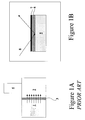
- Figure 1A represents a set-up used to determine the permeability of thicker films such as membranes towards solvents.
- a membrane 3 is placed in between a first volume 1 and a second volume 2.
- the first volume 1 is making contact to a first side of the membrane 3 and contains a high amount of solvent vapor.
- the second volume 2 making contact with a second side opposite to the first side of the membrane 3, the amount of solvent that can penetrate through the pores of the membrane 3 is measured by e.g. Mass Spectrometry using a mass spectrometer 4.
- This method is suitable to measure the permeability of rather thick layers having dimensions up to several microns that can be placed in a container without a carrier, but is not suitable for thin films and coatings with a thickness below 1 ⁇ m, which cannot be removed from their substrate (or carrier).
- the current invention discloses a method making it possible to determine the permeability and/or diffusion rate of solvents through thin films or top coatings having a thickness below 1 ⁇ m, with a minimum thickness in the range of 1 nm that cannot be isolated from or handled without a substrate or carrier.
- the method to determine the permeability of thin films or coatings towards solvents is schematically shown in Figure 1B and starts by depositing an absorption layer, also referred to as container layer 6, onto a substrate 5.
- the absorption or container layer 6 may be deposited onto the substrate 5 using any suitable deposition technique known by a person skilled in the art, such as e.g. chemical vapor deposition (CVD) techniques or spin-on techniques.
- the substrate 5 may preferably have a flat surface and may preferably be a silicon wafer. According to other embodiments of the invention, other semiconductor wafers, such as e.g. GaAs, may also be used.
- the absorption or container layer 6 may be chosen as a function of the solvent to be studied.
- the absorption or container layer 6 may preferably be made of hydrophilic material that easily absorbs water.
- the solvent to be studied and the absorption or container layer 6 used to absorb the solvent have either both hydrophobic properties or hydrophilic properties.
- the solvent to be studied has a low contact angle or good wetting ability towards the absorption or container layer 6.
- the absorption or container layer 6 may preferably be a porous material having pores with relative small pore sizes, because such porous materials have a high absorption capacity into their pores. Most preferred the pores of said porous material may be significantly smaller (e.g.
- suitable porous materials to be used as absorption or container layer 6 are commonly used low-k material in semiconductor processing such as porous Nano-Clustered Silica (NCS) or Chemically Vapor deposited (CVD) low-k material, for example (hydrogenated) silicon-oxy-carbide materials (SiCO(H)) such as ® Black Diamond and ® Aurora. (SiCO(H)).
- suitable porous materials are zeolites; these materials are generally hydrophilic.
- the absorption or container layer 6 may need to be activated to enhance absorption towards the solvent to be studied. Therefore, an additional treatment may have to be done before depositing the thin film or coating 7 on top of it. Examples of such treatments may be methods known by persons skilled in the art such as, for example, methods used to transform a hydrophobic material into a hydrophilic material or vice versa.
- the absorption or container layer 6, e.g. SiCO(H) material may first be made hydrophilic by means of e.g. an anneal process.
- the absorption or container layer 6 When the absorption or container layer 6 is formed by zeolites, the absorption or container layer 6 may be UV-cured, hereby breaking OH-bonds in the zeolites, for making it hydrophobic or may be damaged in e.g. a O 2 plasma, hereby making it hydrophylic.
- the thickness of the absorption or container layer 6 may preferably be significantly thicker than the thickness of the thin layer or coating 7 such that sufficient amount of solvent, e.g. water, can be absorbed or condensed and there is sufficient time to study the evaporation kinetics later on during permeability measurements, i.e. that there is sufficient time before the solvent vapor is completely absorbed and desorbed again.
- the minimum thickness of the absorption or container layer 6 used may be dependent on the analytical tool used to study the evaporation kinetics in the absorption or container layer 6. For example, using e.g. ellipsometry the minimum thickness of the absorption or container layer 6 may preferably be around 50 nm.
- the thin film or top coating 7 to be studied is deposited onto the absorption or container layer 6.
- the substrate 5 comprising the absorption or container layer 6 and a thin film or coating layer 7 on top of the absorption or container layer 6 is then transferred into a pressurizable chamber and the pressure is decreased.
- the pressure may preferably be decreased to a level of 10 -2 -10 -3 Torr or below (to which will be referred to in this application as vacuum).
- the minimum pressure depends on the equilibrium vapor pressure of the solvent of interest. Most solvents, which are in liquid phase at room temperature, may have equilibrium vapor pressures between 10 to 100 Torr and a decreased level of 10 -2 -10 -3 Torr may be sufficient for these solvent.
- the pressurizable chamber is then filled with a gaseous substance of the solvent to be studied, also called solvent moisture, and the pressure in the pressurizable chamber is gradually increased from vacuum up to the equilibrium vapor pressure of the solvent such that the solvent penetrates through the thin film or top coating 7 and is actively absorbed or condensed into the absorption or container layer 6.
- the velocity at which solvent moisture is penetrating into the absorption or container layer 6 can be monitored through the change in pressure.
- a first value of a parameter indicative of the amount of solvent absorbed in the container layer 6 is measured. Thereafter, the pressure in the pressurizable chamber is decreased very fast such that the solvent is desorbed or released from the absorption or container layer 7.
- the degree of filling of the absorption or container layer 7 is monitored using Lorentz-Lorenz equation (as illustrated in equation 2, see further).
- a second value of the parameter indicative of the amount of solvent absorbed in the container layer 6 is measured.
- the pressure may be decreased to a level of 10 -2 -10 -3 Torr or below (to which will referred to in this application as vacuum).
- the amount of solvent absorbed must be sufficient to be detected afterwards by analytical tools. For example, in the case of ellipsometry, where the amount of solvent absorbed is determined by measuring a change in refractive index, a change of 0.02 in refractive index between the absorption or container layer 6 with and without solvent in its pores may provide sufficient sensitivity.
- open porosity is meant the ratio of accessible pore volume to the total pore volume, accessible meaning connected to the surface of the sample. Or in other words, the ratio of pore volume that can be filled with the solvent to be studied to the total pore volume.
- the accessible pore volume can be different from the total pore volume because the material can comprise dead-end pores and/or non-connected cavities, the latter meaning that the pores are formed in the material but do not appear at the surface of the material and thus, cannot be filled with the solvent to be studied.
- open porosity also called effective porosity, refers to the fraction of the total pore volume which is filled with the solvent to be studied.
- the maximum amount of the absorbed solvent e.g. water
- the maximum amount of the absorbed solvent is a measure for the porosity of the absorption or container layer 6.
- Most of the suitable low-k materials used as absorption or container layers 6 may have porosity values between 30-50%.
- the desorption process is limited and defined by diffusion through the thin film or top coating 7.
- the amount of solvent that can diffuse through the thin film or top coating 7 as a function of time is a measure for the permeability of the thin film or top coating 7. This amount of solvent is determined from the first and second values of the parameter indicative of the amount of absorbed solvent in the container layer as determined above.
- the amount of solvent diffused through the thin film or top coating 7 as a function of decrease/increase in pressure may be Ellipsometry, also referred to as Ellipsometric measurements or Ellipsometric porosimetry measurements.
- Ellipsometry measures the change in state of light reflected from the surface of a sample. Ellipsometric measurements are based on the analysis of hysteresis loops that appear due to processes of capillary condensation in absorption and desorption of vapor out of pores of a porous material. The hysteresis loops appear because the effective radius of curvature of a condensed liquid meniscus is different during the absorption and desorption processes.
- the ellipsometric porosimetry measurement technique is reviewed in " The Optics Source Book", Editor Sybil P. Parker, 1988, McGraw-Hill . The ellipsometric measurements are performed using single or multiwave length ellipsometry.
- V 1 the amount of solvent (expressed as volume) penetrated through a coating or thin film 7 (or in other words the volume of condensed liquid)
- V l S ⁇ d ⁇ P 100
- N 6 l ⁇ ⁇ ⁇ N M
- ⁇ is the density of the diffusing solvent, e.g. water.
- the net flow (Phi) through the thin film or top coating 7 is directly proportional to the diffusion constant.
- the diffusion coefficient is proportional to pore size and inversely proportional to the viscosity of diffused liquid and pores tortuousity.
- the tortuousity of pores is a variable which defines the straightness of the flow paths of e.g. a solvent in the pores, and is thus related to the shape of the pores. For example, a pore having the shape of a straight tube may have a tortuousity of 1, whereas common porous materials may have tortuousity values between 2 and 5.
- the tortuousity can experimentally be determined from resistivity measurements.
- Equations (4) and (5) also allow to estimate a range of thicknesses for the thin film or top coating 7 that can be evaluated for determining the permeability of the thin film or top coating 7 by e.g. using ellipsometry as analytical tool.
- the minimum thickness of a top coating or thin film 7 can be derived from absorption-desorption graphs e.g. as illustrated in Figure 3A and 3B for a coated NCS film. This figure shows results of evaluation for a 10 nm thick top coating 7 deposited on top of a porous NCS film used as an absorption or container layer 6. It can be seen that the time between two measurements is about 20 s and two measurements were done in the region of the linear slope of the desorption curve.
- the metrology of the invention is suitable to evaluate layers with a thickness of a few nm, for example 5 nm.
- the minimum thickness of the top coating 7 can be reduced up to 1 nm (limited by pumping speed) using more fast ellipsometric tools such as for instance a single wavelength laser ellipsometer.
- the maximum thickness of a top coating or thin film 7 that can be evaluated for permeability using the method according to the invention and preferably with ellipsometry as analytical tool, may be defined (or limited) by a reasonable time that can be used for the permeability measurements.
- the linear desorption region, as shown in Figure 3B corresponds to 10 s.
- the above estimations show that the proposed method according to the invention can be used for evaluation of top coatings 7 with a thickness varying from 1 nm to several microns (e.g. to 36 ⁇ m).
- the analytical tool to measure the amount of solvent diffused through the thin film or top coating 7 as a function of decrease/increase in pressure may be Mass Spectrometry.
- the present invention also includes a system for determining the permeability of a film (7) towards a solvent using a substrate (5) with a container layer (6) in between the substrate (5) and a film (7).
- the system comprises a pressurizable chamber for holding said substrate (5) comprising the container layer (6) and film (7), as well as means for controlling operation of the pressurizable chamber, e.g. a suitable electronic controller such as a microcontroller.
- the controller is adapted to carry out a series of steps as indicated above for any of the embodiments of the present invention, e.g.
- the controller may include (or there could be a separate device responsive to an output of the controller including) means for determining a first value of a parameter indicative of the amount of solvent absorbed in the container layer (6).
- the controller is also adapted to decrease the pressure in said pressurizable chamber thereafter such that the absorbed solvent diffuses back through the film (7).
- the controller may include (or there could be a separate device responsive to an output of the controller including) means for determining a second value of the parameter indicative of the amount of solvent absorbed in the container layer (6).
- the controller may include (or there could be a separate device responsive to an output of the controller including) means for determining from the first and second values of the parameter indicative of the amount of absorbed solvent in the container layer, the amount of solvent diffusing through the film (7), the amount of solvent diffused through the film (7) being a measure for the permeability of the film (7) towards the solvent.
- the means for determining may be implemented as a microcontroller or any other computational device, e.g. a specifically programmed microprocessor, such as an embedded microprocessor or an FPGA.
- the controller may be adapted to decrease the pressure in the pressurizable chamber to a level of 10 -2 -10 -3 Torr or below.
- the presurized chamber may have a pressure transducer coupled to the controller providing feedback as to the pressure therein for control purposes.
- the means for determining the amount of solvent diffusing through said film (7) may also include means for ellipsometric measurements and/or means for Mass Spectrometric measurements as described above.
- the method according to the invention can, for example, be used to predict or determine solvent permeability or penetration in a variety of thin films or coatings 7 .
- a lot of application fields are possible and the invention is not limited to the examples and applications given below.
- top coatings 7 may be deposited onto photosensitive layers or resists, to protect the photosensitive layers from leaching and degradation effects originating from contact with the immersion liquid.
- the method according to the invention can be applied and will not only give information about the amount of immersion liquid (e.g. water) taken up by the top coatings 7 but also about the permeability or diffusion rate of the immersion liquid through the top coatings 7.
- Example 1 Ellipsometric measurements to determine diffusion rate of water in a hydrophilic and hydrophobic SiCO(H) low-k material
- Figure 2A illustrates the change of pressure in the pressurizable chamber as a function of time for a first SiOC material (A).
- Figure 2B shows the change in absorptive mass (solvent) as a function of time for the first SiOC material (A) and for a second SiOC material (D).
- the first SiOC material (A) may, according to this example, be a hydrophobic SiOC(H) low k-material.
- the second SiOC material (D) may, according to this example, be a (pre-treated) hydrophilic low-k SiOC(H).
- the change in (vapor) pressure is the same as the absorbed mass of solvent.
- the diffusion rate is thus the same as the change in pressure and therefore the process is limited by absorption (not diffusion).
- the absorption/desorption rate is much smaller than in the second SiOC material (D) and is also determined by diffusion and not only by absorption/desorption.
- Example 2 Determination of the amount of water permeated through a top coating used in immersion lithography using a NCS (Nano Clustered Silica) layer as container layer.
- NCS Nano Clustered Silica
- NCS Nano Clustered Silica
- the NCS layer 6 is coated onto a substrate 5; the thickness of the NCS layer 6 is 400 nm and has a porosity (P) of 30%.
- the NCS container layer 6 is covered by a top coating 7.
- the top coating 7 is used in immersion lithography as a protective coating for photosensitive layers.
- the container layer (NCS) 6 is completely saturated with water by transferring said substrate 5 into a pressurizable chamber, which is filled with water vapor, which diffuses through the top coating 7 ( Figure 3A, absorption region) into the NCS layer 6.
- the time needed to desorb the water (evaporation) from the NCS layer 6 through the top coating 7 can be
Landscapes
- Chemical & Material Sciences (AREA)
- Physics & Mathematics (AREA)
- General Physics & Mathematics (AREA)
- Immunology (AREA)
- Life Sciences & Earth Sciences (AREA)
- Analytical Chemistry (AREA)
- Biochemistry (AREA)
- General Health & Medical Sciences (AREA)
- Dispersion Chemistry (AREA)
- Health & Medical Sciences (AREA)
- Pathology (AREA)
- Fluid Mechanics (AREA)
- Investigating Or Analysing Materials By Optical Means (AREA)
- Investigating Or Analyzing Non-Biological Materials By The Use Of Chemical Means (AREA)
- Other Investigation Or Analysis Of Materials By Electrical Means (AREA)
- Separation Using Semi-Permeable Membranes (AREA)
Applications Claiming Priority (1)
| Application Number | Priority Date | Filing Date | Title |
|---|---|---|---|
| US75344905P | 2005-12-22 | 2005-12-22 |
Publications (3)
| Publication Number | Publication Date |
|---|---|
| EP1801559A2 true EP1801559A2 (de) | 2007-06-27 |
| EP1801559A3 EP1801559A3 (de) | 2007-11-21 |
| EP1801559B1 EP1801559B1 (de) | 2010-07-21 |
Family
ID=37575961
Family Applications (1)
| Application Number | Title | Priority Date | Filing Date |
|---|---|---|---|
| EP06447068A Expired - Lifetime EP1801559B1 (de) | 2005-12-22 | 2006-05-23 | Verfahren zur Bestimmung der Lösungsmitteldurchlässigkeit von Filmen |
Country Status (5)
| Country | Link |
|---|---|
| US (1) | US7458251B2 (de) |
| EP (1) | EP1801559B1 (de) |
| JP (1) | JP4892333B2 (de) |
| AT (1) | ATE475078T1 (de) |
| DE (1) | DE602006015595D1 (de) |
Cited By (3)
| Publication number | Priority date | Publication date | Assignee | Title |
|---|---|---|---|---|
| GB2456295A (en) * | 2007-12-04 | 2009-07-15 | Montfort Services Sdn Bhd | Method and apparatus for measuring the absorption of a volatile compound |
| FR3026846A1 (fr) * | 2014-10-03 | 2016-04-08 | Commissariat Energie Atomique | Dispositif de mesure du gonflement et de l'impregnation d'un enrobe bitumineux en contact avec une solution de lixiviation, et procede associe |
| CN109238155A (zh) * | 2018-11-01 | 2019-01-18 | 上海市计量测试技术研究院 | 采用等效物理结构模型测量SiO2薄膜厚度的方法 |
Families Citing this family (8)
| Publication number | Priority date | Publication date | Assignee | Title |
|---|---|---|---|---|
| FR2886015B1 (fr) * | 2005-05-18 | 2007-07-13 | Commissariat Energie Atomique | Procede de mesure de la porosite par ellipsometrie et dispositif mettant en oeuvre un tel procede |
| US7907264B1 (en) * | 2007-09-07 | 2011-03-15 | Kla-Tencor Corporation | Measurement of thin film porosity |
| US8711356B2 (en) * | 2010-02-25 | 2014-04-29 | Stichting Imec Nederland | Gas sensor with a porous layer that detectably affects a surface lattice resonant condition of a nanoparticle array |
| JP5849370B2 (ja) * | 2011-08-22 | 2016-01-27 | 住友化学株式会社 | ガスバリア性積層フィルムの検査方法、ガスバリア性積層フィルムの製造方法、ガスバリア性積層フィルムを使用した電子デバイスの検査方法およびガスバリア性積層フィルムを使用した電子デバイスの製造方法 |
| SG11201600947PA (en) * | 2013-10-08 | 2016-03-30 | Univ Nanyang Tech | Method and arrangement for determining at least one pore-related parameter of a porous material |
| US9546943B1 (en) * | 2015-03-21 | 2017-01-17 | J.A. Woollam Co., Inc | System and method for investigating change in optical properties of a porous effective substrate surface as a function of a sequence of solvent partial pressures at atmospheric pressure |
| CN108007843B (zh) * | 2017-12-19 | 2024-01-30 | 中国石油天然气集团公司 | 一种用于评价高温高压下溶解氧在防腐涂层中渗透性的装置及方法 |
| CN113289845B (zh) * | 2021-04-07 | 2023-09-29 | 浙江普汇电子科技有限公司 | 一种局部排气和分格检测法加速氨纶底襟生产装置 |
Family Cites Families (7)
| Publication number | Priority date | Publication date | Assignee | Title |
|---|---|---|---|---|
| US6319736B1 (en) * | 1998-08-28 | 2001-11-20 | Interuniversitair Microelektronica Centrum (Imec) | Apparatus and method for determining porosity |
| DE20000779U1 (de) * | 2000-01-18 | 2000-08-03 | Illing, Gerhard, 26721 Emden | Differenzdruckmeßsystem zur Bestimmung der Permeabilität, der Sorption und des Diffusionskoeffizienten stoffdurchlässiger Materialien |
| EP1172847A3 (de) * | 2000-07-10 | 2004-07-28 | Interuniversitair Micro-Elektronica Centrum Vzw | Methode, eine poröse Siliziumoxidschicht herzustellen |
| US6766682B2 (en) * | 2001-10-19 | 2004-07-27 | Desert Cryogenics Llc | Precise measurement system for barrier materials |
| JP3958235B2 (ja) * | 2002-04-05 | 2007-08-15 | 住友ベークライト株式会社 | 水蒸気バリア性評価用セルおよび水蒸気バリア性評価方法 |
| US6981403B2 (en) * | 2003-10-31 | 2006-01-03 | Mocon, Inc. | Method and apparatus for measuring gas transmission rates of deformable or brittle materials |
| JP2007040712A (ja) * | 2005-07-29 | 2007-02-15 | Takenaka Komuten Co Ltd | 塗材の透気性試験方法及びコンクリートの中性化率算出方法 |
-
2006
- 2006-05-23 AT AT06447068T patent/ATE475078T1/de not_active IP Right Cessation
- 2006-05-23 DE DE602006015595T patent/DE602006015595D1/de not_active Expired - Lifetime
- 2006-05-23 EP EP06447068A patent/EP1801559B1/de not_active Expired - Lifetime
- 2006-12-06 US US11/634,410 patent/US7458251B2/en active Active
- 2006-12-22 JP JP2006346094A patent/JP4892333B2/ja active Active
Cited By (3)
| Publication number | Priority date | Publication date | Assignee | Title |
|---|---|---|---|---|
| GB2456295A (en) * | 2007-12-04 | 2009-07-15 | Montfort Services Sdn Bhd | Method and apparatus for measuring the absorption of a volatile compound |
| FR3026846A1 (fr) * | 2014-10-03 | 2016-04-08 | Commissariat Energie Atomique | Dispositif de mesure du gonflement et de l'impregnation d'un enrobe bitumineux en contact avec une solution de lixiviation, et procede associe |
| CN109238155A (zh) * | 2018-11-01 | 2019-01-18 | 上海市计量测试技术研究院 | 采用等效物理结构模型测量SiO2薄膜厚度的方法 |
Also Published As
| Publication number | Publication date |
|---|---|
| DE602006015595D1 (de) | 2010-09-02 |
| EP1801559A3 (de) | 2007-11-21 |
| JP2007171204A (ja) | 2007-07-05 |
| ATE475078T1 (de) | 2010-08-15 |
| JP4892333B2 (ja) | 2012-03-07 |
| US20070148327A1 (en) | 2007-06-28 |
| EP1801559B1 (de) | 2010-07-21 |
| US7458251B2 (en) | 2008-12-02 |
Similar Documents
| Publication | Publication Date | Title |
|---|---|---|
| Zangooie et al. | Vapor sensitivity of thin porous silicon layers | |
| EP1801559B1 (de) | Verfahren zur Bestimmung der Lösungsmitteldurchlässigkeit von Filmen | |
| Ruminski et al. | Humidity‐compensating sensor for volatile organic compounds using stacked porous silicon photonic crystals | |
| Zhao et al. | Wetting properties of thin liquid polyethylene propylene films | |
| US7042570B2 (en) | Porous thin film time-varying reflectivity analysis of samples | |
| US10041873B2 (en) | Porosity measurement of semiconductor structures | |
| US20110019207A1 (en) | Method for optical characterisation | |
| US7685865B2 (en) | Method and apparatus for measuring the rate of permeation | |
| CN1096286C (zh) | 薄膜过滤系统对数降低值预测及多孔薄膜完整性试验方法 | |
| EP1032816B1 (de) | Vorrichtung und verfahren zur bestimmung der porosität | |
| US20120184047A1 (en) | Nanoplasmonic device | |
| US20070108465A1 (en) | Porous microstructure multi layer spectroscopy and biosensing | |
| TW201805617A (zh) | 在氣體吸附下之關鍵尺寸量測 | |
| Arwin et al. | Protein adsorption in thin porous silicon layers | |
| Çapan et al. | A new approach for the adsorption kinetics using surface plasmon resonance results | |
| TW201740094A (zh) | 以毛細管冷凝法量測半導體結構 | |
| Zangooie et al. | Water interaction with thermally oxidized porous silicon layers | |
| US7399449B1 (en) | Microfabricated diffusion source | |
| Füredi et al. | Disentangling adsorption and absorption in microporous polymers | |
| Klyui et al. | Features of the use of optical reflection from thin porous silicon for detection of organic liquids | |
| Dammel et al. | Resist component leaching in 193-nm immersion lithography | |
| EP1722213B1 (de) | Verfahren zur Quantifizierung der hydrophilen Eigenschaften poröser Materialien | |
| Eloy-Giorni et al. | Water diffusion through geomembranes under hydraulic pressure | |
| Baklanov et al. | Characterisation of low-k dielectric films by ellipsometric porosimetry | |
| Shamiryan et al. | Solvent diffusion in porous low-k dielectric films |
Legal Events
| Date | Code | Title | Description |
|---|---|---|---|
| PUAI | Public reference made under article 153(3) epc to a published international application that has entered the european phase |
Free format text: ORIGINAL CODE: 0009012 |
|
| AK | Designated contracting states |
Kind code of ref document: A2 Designated state(s): AT BE BG CH CY CZ DE DK EE ES FI FR GB GR HU IE IS IT LI LT LU LV MC NL PL PT RO SE SI SK TR |
|
| AX | Request for extension of the european patent |
Extension state: AL BA HR MK YU |
|
| PUAL | Search report despatched |
Free format text: ORIGINAL CODE: 0009013 |
|
| AK | Designated contracting states |
Kind code of ref document: A3 Designated state(s): AT BE BG CH CY CZ DE DK EE ES FI FR GB GR HU IE IS IT LI LT LU LV MC NL PL PT RO SE SI SK TR |
|
| AX | Request for extension of the european patent |
Extension state: AL BA HR MK YU |
|
| 17P | Request for examination filed |
Effective date: 20080521 |
|
| AKX | Designation fees paid |
Designated state(s): AT BE BG CH CY CZ DE DK EE ES FI FR GB GR HU IE IS IT LI LT LU LV MC NL PL PT RO SE SI SK TR |
|
| RAP1 | Party data changed (applicant data changed or rights of an application transferred) |
Owner name: IMEC |
|
| GRAP | Despatch of communication of intention to grant a patent |
Free format text: ORIGINAL CODE: EPIDOSNIGR1 |
|
| GRAS | Grant fee paid |
Free format text: ORIGINAL CODE: EPIDOSNIGR3 |
|
| GRAA | (expected) grant |
Free format text: ORIGINAL CODE: 0009210 |
|
| AK | Designated contracting states |
Kind code of ref document: B1 Designated state(s): AT BE BG CH CY CZ DE DK EE ES FI FR GB GR HU IE IS IT LI LT LU LV MC NL PL PT RO SE SI SK TR |
|
| REG | Reference to a national code |
Ref country code: GB Ref legal event code: FG4D |
|
| REG | Reference to a national code |
Ref country code: CH Ref legal event code: EP |
|
| REG | Reference to a national code |
Ref country code: IE Ref legal event code: FG4D |
|
| REF | Corresponds to: |
Ref document number: 602006015595 Country of ref document: DE Date of ref document: 20100902 Kind code of ref document: P |
|
| REG | Reference to a national code |
Ref country code: NL Ref legal event code: VDEP Effective date: 20100721 |
|
| LTIE | Lt: invalidation of european patent or patent extension |
Effective date: 20100721 |
|
| PG25 | Lapsed in a contracting state [announced via postgrant information from national office to epo] |
Ref country code: AT Free format text: LAPSE BECAUSE OF FAILURE TO SUBMIT A TRANSLATION OF THE DESCRIPTION OR TO PAY THE FEE WITHIN THE PRESCRIBED TIME-LIMIT Effective date: 20100721 Ref country code: FI Free format text: LAPSE BECAUSE OF FAILURE TO SUBMIT A TRANSLATION OF THE DESCRIPTION OR TO PAY THE FEE WITHIN THE PRESCRIBED TIME-LIMIT Effective date: 20100721 Ref country code: LT Free format text: LAPSE BECAUSE OF FAILURE TO SUBMIT A TRANSLATION OF THE DESCRIPTION OR TO PAY THE FEE WITHIN THE PRESCRIBED TIME-LIMIT Effective date: 20100721 Ref country code: NL Free format text: LAPSE BECAUSE OF FAILURE TO SUBMIT A TRANSLATION OF THE DESCRIPTION OR TO PAY THE FEE WITHIN THE PRESCRIBED TIME-LIMIT Effective date: 20100721 |
|
| PG25 | Lapsed in a contracting state [announced via postgrant information from national office to epo] |
Ref country code: IS Free format text: LAPSE BECAUSE OF FAILURE TO SUBMIT A TRANSLATION OF THE DESCRIPTION OR TO PAY THE FEE WITHIN THE PRESCRIBED TIME-LIMIT Effective date: 20101121 Ref country code: SI Free format text: LAPSE BECAUSE OF FAILURE TO SUBMIT A TRANSLATION OF THE DESCRIPTION OR TO PAY THE FEE WITHIN THE PRESCRIBED TIME-LIMIT Effective date: 20100721 Ref country code: BG Free format text: LAPSE BECAUSE OF FAILURE TO SUBMIT A TRANSLATION OF THE DESCRIPTION OR TO PAY THE FEE WITHIN THE PRESCRIBED TIME-LIMIT Effective date: 20101021 Ref country code: CY Free format text: LAPSE BECAUSE OF FAILURE TO SUBMIT A TRANSLATION OF THE DESCRIPTION OR TO PAY THE FEE WITHIN THE PRESCRIBED TIME-LIMIT Effective date: 20100721 Ref country code: PL Free format text: LAPSE BECAUSE OF FAILURE TO SUBMIT A TRANSLATION OF THE DESCRIPTION OR TO PAY THE FEE WITHIN THE PRESCRIBED TIME-LIMIT Effective date: 20100721 Ref country code: PT Free format text: LAPSE BECAUSE OF FAILURE TO SUBMIT A TRANSLATION OF THE DESCRIPTION OR TO PAY THE FEE WITHIN THE PRESCRIBED TIME-LIMIT Effective date: 20101122 |
|
| PG25 | Lapsed in a contracting state [announced via postgrant information from national office to epo] |
Ref country code: SE Free format text: LAPSE BECAUSE OF FAILURE TO SUBMIT A TRANSLATION OF THE DESCRIPTION OR TO PAY THE FEE WITHIN THE PRESCRIBED TIME-LIMIT Effective date: 20100721 Ref country code: BE Free format text: LAPSE BECAUSE OF FAILURE TO SUBMIT A TRANSLATION OF THE DESCRIPTION OR TO PAY THE FEE WITHIN THE PRESCRIBED TIME-LIMIT Effective date: 20100721 Ref country code: LV Free format text: LAPSE BECAUSE OF FAILURE TO SUBMIT A TRANSLATION OF THE DESCRIPTION OR TO PAY THE FEE WITHIN THE PRESCRIBED TIME-LIMIT Effective date: 20100721 Ref country code: GR Free format text: LAPSE BECAUSE OF FAILURE TO SUBMIT A TRANSLATION OF THE DESCRIPTION OR TO PAY THE FEE WITHIN THE PRESCRIBED TIME-LIMIT Effective date: 20101022 |
|
| PG25 | Lapsed in a contracting state [announced via postgrant information from national office to epo] |
Ref country code: DK Free format text: LAPSE BECAUSE OF FAILURE TO SUBMIT A TRANSLATION OF THE DESCRIPTION OR TO PAY THE FEE WITHIN THE PRESCRIBED TIME-LIMIT Effective date: 20100721 |
|
| PLBE | No opposition filed within time limit |
Free format text: ORIGINAL CODE: 0009261 |
|
| STAA | Information on the status of an ep patent application or granted ep patent |
Free format text: STATUS: NO OPPOSITION FILED WITHIN TIME LIMIT |
|
| PG25 | Lapsed in a contracting state [announced via postgrant information from national office to epo] |
Ref country code: IT Free format text: LAPSE BECAUSE OF FAILURE TO SUBMIT A TRANSLATION OF THE DESCRIPTION OR TO PAY THE FEE WITHIN THE PRESCRIBED TIME-LIMIT Effective date: 20100721 Ref country code: CZ Free format text: LAPSE BECAUSE OF FAILURE TO SUBMIT A TRANSLATION OF THE DESCRIPTION OR TO PAY THE FEE WITHIN THE PRESCRIBED TIME-LIMIT Effective date: 20100721 Ref country code: SK Free format text: LAPSE BECAUSE OF FAILURE TO SUBMIT A TRANSLATION OF THE DESCRIPTION OR TO PAY THE FEE WITHIN THE PRESCRIBED TIME-LIMIT Effective date: 20100721 Ref country code: RO Free format text: LAPSE BECAUSE OF FAILURE TO SUBMIT A TRANSLATION OF THE DESCRIPTION OR TO PAY THE FEE WITHIN THE PRESCRIBED TIME-LIMIT Effective date: 20100721 Ref country code: EE Free format text: LAPSE BECAUSE OF FAILURE TO SUBMIT A TRANSLATION OF THE DESCRIPTION OR TO PAY THE FEE WITHIN THE PRESCRIBED TIME-LIMIT Effective date: 20100721 |
|
| 26N | No opposition filed |
Effective date: 20110426 |
|
| PG25 | Lapsed in a contracting state [announced via postgrant information from national office to epo] |
Ref country code: ES Free format text: LAPSE BECAUSE OF FAILURE TO SUBMIT A TRANSLATION OF THE DESCRIPTION OR TO PAY THE FEE WITHIN THE PRESCRIBED TIME-LIMIT Effective date: 20101101 |
|
| REG | Reference to a national code |
Ref country code: DE Ref legal event code: R097 Ref document number: 602006015595 Country of ref document: DE Effective date: 20110426 |
|
| PG25 | Lapsed in a contracting state [announced via postgrant information from national office to epo] |
Ref country code: MC Free format text: LAPSE BECAUSE OF NON-PAYMENT OF DUE FEES Effective date: 20110531 |
|
| REG | Reference to a national code |
Ref country code: CH Ref legal event code: PL |
|
| PG25 | Lapsed in a contracting state [announced via postgrant information from national office to epo] |
Ref country code: CH Free format text: LAPSE BECAUSE OF NON-PAYMENT OF DUE FEES Effective date: 20110531 Ref country code: LI Free format text: LAPSE BECAUSE OF NON-PAYMENT OF DUE FEES Effective date: 20110531 |
|
| REG | Reference to a national code |
Ref country code: IE Ref legal event code: MM4A |
|
| PG25 | Lapsed in a contracting state [announced via postgrant information from national office to epo] |
Ref country code: IE Free format text: LAPSE BECAUSE OF NON-PAYMENT OF DUE FEES Effective date: 20110523 |
|
| PG25 | Lapsed in a contracting state [announced via postgrant information from national office to epo] |
Ref country code: LU Free format text: LAPSE BECAUSE OF NON-PAYMENT OF DUE FEES Effective date: 20110523 |
|
| PG25 | Lapsed in a contracting state [announced via postgrant information from national office to epo] |
Ref country code: TR Free format text: LAPSE BECAUSE OF FAILURE TO SUBMIT A TRANSLATION OF THE DESCRIPTION OR TO PAY THE FEE WITHIN THE PRESCRIBED TIME-LIMIT Effective date: 20100721 |
|
| PG25 | Lapsed in a contracting state [announced via postgrant information from national office to epo] |
Ref country code: HU Free format text: LAPSE BECAUSE OF FAILURE TO SUBMIT A TRANSLATION OF THE DESCRIPTION OR TO PAY THE FEE WITHIN THE PRESCRIBED TIME-LIMIT Effective date: 20100721 |
|
| REG | Reference to a national code |
Ref country code: FR Ref legal event code: PLFP Year of fee payment: 11 |
|
| REG | Reference to a national code |
Ref country code: FR Ref legal event code: PLFP Year of fee payment: 12 |
|
| REG | Reference to a national code |
Ref country code: FR Ref legal event code: PLFP Year of fee payment: 13 |
|
| P01 | Opt-out of the competence of the unified patent court (upc) registered |
Effective date: 20230513 |
|
| PGFP | Annual fee paid to national office [announced via postgrant information from national office to epo] |
Ref country code: DE Payment date: 20250423 Year of fee payment: 20 |
|
| PGFP | Annual fee paid to national office [announced via postgrant information from national office to epo] |
Ref country code: GB Payment date: 20250423 Year of fee payment: 20 |
|
| PGFP | Annual fee paid to national office [announced via postgrant information from national office to epo] |
Ref country code: FR Payment date: 20250423 Year of fee payment: 20 |
|
| REG | Reference to a national code |
Ref country code: DE Ref legal event code: R071 Ref document number: 602006015595 Country of ref document: DE |
|
| REG | Reference to a national code |
Ref country code: GB Ref legal event code: PE20 Expiry date: 20260522 |
|
| PG25 | Lapsed in a contracting state [announced via postgrant information from national office to epo] |
Ref country code: GB Free format text: LAPSE BECAUSE OF EXPIRATION OF PROTECTION Effective date: 20260522 |