EP1801763A2 - Verfahren zum Übertragen von Infrarot-Fernsteuerdaten und Erlernen einer Infrarot-Fernsteuervorrichtung - Google Patents
Verfahren zum Übertragen von Infrarot-Fernsteuerdaten und Erlernen einer Infrarot-Fernsteuervorrichtung Download PDFInfo
- Publication number
- EP1801763A2 EP1801763A2 EP06016954A EP06016954A EP1801763A2 EP 1801763 A2 EP1801763 A2 EP 1801763A2 EP 06016954 A EP06016954 A EP 06016954A EP 06016954 A EP06016954 A EP 06016954A EP 1801763 A2 EP1801763 A2 EP 1801763A2
- Authority
- EP
- European Patent Office
- Prior art keywords
- infrared
- signal
- data
- remote control
- control device
- Prior art date
- Legal status (The legal status is an assumption and is not a legal conclusion. Google has not performed a legal analysis and makes no representation as to the accuracy of the status listed.)
- Withdrawn
Links
Images

Classifications
-
- G—PHYSICS
- G08—SIGNALLING
- G08C—TRANSMISSION SYSTEMS FOR MEASURED VALUES, CONTROL OR SIMILAR SIGNALS
- G08C19/00—Electric signal transmission systems
- G08C19/16—Electric signal transmission systems in which transmission is by pulses
- G08C19/28—Electric signal transmission systems in which transmission is by pulses using pulse code
Definitions
- the present invention relates to a learning-type (intelligent) infra-red remote control device used to remotely operate or control household appliances and the like using a personal computer.
- the present invention also relates to a device for connecting through USB communications an infrared control device that sends and receives infrared light and a host such as a personal computer.
- infrared signals used in infrared remote control devices in electric home appliances include the signal format of the Kaden Seihin Kyoukai (the Association for Electric Home Appliances) (the Kadenkyo format) and manufacturers' formats that provide extensions and modifications of the same.
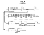
- the basic structure of the signal shown in Fig. 4, is formed from: a header (a) indicating the start of a transmission signal + a custom code (b) indicating the control (instruction) type + a data code (c) indicating the contents of the control + an end bit (d) indicating the end of the transmission signal; a repeat header (e); and a repeat end bit (f).
- the time interval for one entire pulse from the leading edge (on) to the trailing edge (off) of a pulse and then to the leading edge of the next pulse is referred to as the pulse width.
- the time from the leading edge (on) to the trailing edge (off) of the pulse is referred to as the mark width.
- the header (a) has a mark width of 9 ms and a pulse width of 13.5 ms.
- the custom code (b) and the data code (c) are formed from a combination of sixteen "0"s, which have a mark width of 0.56 ms and a pulse width of 1.125 ms, and "1"s, which have a mark width of 0.56 ms and a pulse width of 2.25 ms.
- the end bit (d) has a mark width of 0.56 ms and a pulse width of 40.5 ms.
- the repeat header (e) has a mark width of 9 ms and a pulse width of 11.25 ms.
- the repeat end bit (f) has a mark width of 0.56 ms and a pulse width of 96.75 ms.
- U.S. Patent Application Publication No. 2002/0129289 published on September 12, 2002 , discloses a personal computer having an embedded controller - keyboard controller (ECKBC) that is interconnected with a CPU via a peripheral component interconnect (PCI) bus and associated bridge, and also to an infrared controller.
- EKBC embedded controller - keyboard controller
- PCI peripheral component interconnect
- the CPU is able to access the infrared controller, which thereby is able to operate as a receiver for remote control of the personal computer.
- Publication No. 2002/0129289 was also published on April 5, 2002 as Japanese Patent Publication No. 2002-101476 , and is hereby incorporated by reference herein in its entirety.
- USB Universal Serial Bus
- USB communication is growing in popularity as a communication method between personal computers and peripherals or home appliances.
- USB communication is becoming the primary method for communicating with home appliances, with these appliances being referred to sometimes as USB devices.
- Infrared communication devices are also part of this trend, with USB communication being used frequently with the host CPU, e.g., a personal computer.
- USB Ver. 1.1 Shortly after implementation (USB Ver. 1.1), two types of USB were available: 1.5 Mbps (low-speed) and 12 Mbps (full-speed). For storage devices, e.g., hard drives, that send and receive large amounts of data, even full-speed USB was inadequate. To address this limitation, subsequent standards (USB Ver. 2.0) have been developed and implemented for 480 Mbps (high-speed) communications.
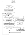
- a learning circuit when learning is started (step F1), a learning circuit initializes memory and the like as necessary (step F2).
- An infrared signal to be learned for the purpose of sampling is transmitted in the direction of an infrared receiver, and the signal received by the receiver is converted to an electrical signal that is sent to the learning circuit.
- the learning circuit performs the following operations to learn the signal.
- step F4 After entering a main learning loop (step F4), a determination is made as to whether sampling has been completed or not (step F4), and if sampling has been completed, the signal data stored in a USB buffer is sent to a host CPU by way of a USB interface (step F15), and the operation is completed (step F11).
- step F5 a determination is made as to whether a signal has been received or not. If there is no input signal, the sampling completion evaluation (step F4) is performed again. If an input signal is present, a mark width, a pulse width, and a carrier count are stored in the USB output buffer (step F14).
- the USB buffer is checked to see if the packet data has filled the buffer (step F9). If the buffer is full, the signal data stored in the USB buffer is sent to the host CPU by way of the USB interface (step F16). Then, control returns to the main learning loop (step F3) to process the next signal.
- USB Universal Asynchronous Receiver Transmitter
- USB Ver.2.0-compatible USB interface is generally provided as a standard feature for connecting to other peripherals.
- USB Ver.1.1 full-speed compatible interface will be required just to transfer data from the infrared remote control device.
- an expensive RISC Reduced Instruction Set Computer
- an internal USB interface that performs full-speed USB communication may be installed.
- an infrared remote control device is equipped with an infrared receiver receiving an infrared signal from an infrared transmitter and converting the signal to an electric signal, and an infrared control device controlling a home appliance based on the signal from the infrared receiver or sending the signal to a host CPU to store the signal.
- Communication between the host CPU and the infrared control device is performed with compression by encoding the signal into PD number data (sequence data) corresponding to each pulse data in the signal.
- the volume of data communicated between the infrared control device and the host CPU can be compressed to 1/8.
- Encoding for data compression is performed by a "look-up" in a table that associates pulse data with PD numbers.
- a single PD number may be represented by 4 bits, in a table containing up to 16 types of pulse data. In this manner, all pulse data used in standard infrared remote control devices can be stored, and the data can be compressed sufficiently to allow communication to take place adequately using USB Ver. 1. low-speed communication.
- a learning infrared remote control device Referring to Fig. 1 through Fig. 3, an embodiment according to the present invention of a learning infrared remote control device will be described.
- a personal computer is used to operate/control a home appliance.
- Input devices such as a keyboard and mouse are also connected through infrared communication.
- Fig. 1 shows the infrared remote control device 1, including an infrared control circuit 2 and a host CPU (personal computer) 3.
- the infrared control circuit 2 is connected to an infrared receiver 4, a learning circuit 5, and an infrared transmitter LED 6.
- the infrared control circuit 2 is also connected to the host CPU 3 by way of a USB Ver.1.1 low-speed compatible interface.
- the infrared control circuit 2, the infrared receiver 4, and the learning circuit 5 may be installed for example in the case of the host CPU 3.
- the infrared transmitter LED 6 is generally set up outside the case of the host CPU 3 since it must be installed in an appropriate position facing a target home appliance 7.
- a remote control 8, a keyboard 9, and a mouse 10 communicate with the infrared control circuit 2 by way of the infrared receiver 4.
- the infrared control circuit 2 is equipped with an internal table 11, in which a PD number is assigned to each type of pulse data.
- pulse data representing infrared signal waveforms can be assigned to PD numbers, e.g., the 16 numbers 0 - 15 represented by 4 bits.
- the header is assigned to PD number 0, "0"s in the custom code and the data code are assigned PD number 1, "1"s in the custom code and the data code are assigned PD number 2, the end bit is assigned PD number 3, the repeat header is assigned PD number 4, and the repeat end bit is assigned PD number 5.
- the infrared signal received by the infrared receiver 4 from the remote control 8 is converted to a corresponding electric signal and sent to the infrared control circuit 2.
- the infrared control circuit 2 analyzes the transferred signal and, based on the results of this analysis, outputs (communicates) associated signals to the CPU 3 and to the external home appliance 7 by way of the infrared transmitter LED 6 and the like.
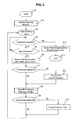
- step G1 When learning is started (step G1), the learning circuit 5 performs initialization needed for the learning operation of the memory and the like (step G2).
- step G2 When an infrared signal to be learned is sent toward the infrared receiver for sampling, the receiver converts the received signal to an electrical signal and sends it via the infrared control circuit 2 to the learning circuit 5.
- the learning circuit 5 performs the following operations to learn the sampled signal.
- step G4 a determination is made as to whether sampling has been completed or not (step G4), and if sampling has been completed the sequence data (PD number series) stored in a USB buffer is sent to a host CPU 3 by way of the infrared control circuit 2 and a USB interface of the host CPU 3 (step G10), and the operation is completed (step G11).
- the host CPU 3 stores this data.
- step G5 a determination is made as to whether a signal has been received or not (step G5). If there is no input signal, the sampling completion evaluation (step G4) is performed again. If an input signal is present, the pulse data (the mark width, the pulse width, and the carrier count) are measured (step G6).
- step G7 An evaluation is performed to see whether the pulse data has already been registered (step G7). If it has not been registered, an available PD number is assigned to the measured pulse data and the information is entered in the table 11. The PD number corresponding to the pulse data is stored in the USB output buffer (step G8).
- the USB buffer is checked to see if the packet data has filled the buffer (step G9). If the buffer is full, the signal data stored in the USB buffer is sent to the host CPU 3 by way of the USB interface (step G13), and the host CPU 3 stores this data. Then, control returns to the main learning loop (step G3) to process the next signal.
- the sequence data output by the learning circuit 5 to the infrared control device 2 for the host CPU 3 to store is encoded by look up in the table 11. For example, in the case of header + "01101011” (custom code) + “01001011” (custom code) + “01100110” (data code) + "00101110” (data code) + end bit, the encoded result output to the host CPU 3 would be "0 12212122 12112122 12211221 11212221 3". (The spaces are inserted simply to delimit the header, the custom codes, the data codes, and the end bit. They would not be used in practice.)
- the sequence data stored in the host CPU 3 is read directly in its compressed form and then decoded into the original signal by looking up the table 11.
- the volume of data communicated can be significantly reduced so that USB Ver.1.1 low-speed communication can be used.
- the cost of the USB interface can be reduced.
- the invention includes combinations and subcombinations of the various elements, features, functions and/or properties disclosed herein.
- the following claims define certain combinations and subcombinations, which are regarded as novel and non-obvious. Additional claims for other combinations and subcombinations of features, functions, elements and/or properties may be presented in this or a related application.
Landscapes
- Physics & Mathematics (AREA)
- General Physics & Mathematics (AREA)
- Selective Calling Equipment (AREA)
Applications Claiming Priority (1)
| Application Number | Priority Date | Filing Date | Title |
|---|---|---|---|
| JP2005367059A JP2007174116A (ja) | 2005-12-20 | 2005-12-20 | 赤外線リモコンデータの通信方法及び学習型赤外線リモコン装置 |
Publications (1)
| Publication Number | Publication Date |
|---|---|
| EP1801763A2 true EP1801763A2 (de) | 2007-06-27 |
Family
ID=37907398
Family Applications (1)
| Application Number | Title | Priority Date | Filing Date |
|---|---|---|---|
| EP06016954A Withdrawn EP1801763A2 (de) | 2005-12-20 | 2006-08-14 | Verfahren zum Übertragen von Infrarot-Fernsteuerdaten und Erlernen einer Infrarot-Fernsteuervorrichtung |
Country Status (3)
| Country | Link |
|---|---|
| US (1) | US20070234383A1 (de) |
| EP (1) | EP1801763A2 (de) |
| JP (1) | JP2007174116A (de) |
Cited By (9)
| Publication number | Priority date | Publication date | Assignee | Title |
|---|---|---|---|---|
| CN102509444A (zh) * | 2011-12-09 | 2012-06-20 | 广东长虹电子有限公司 | 一种数据传输的方法 |
| CN102790621A (zh) * | 2012-06-08 | 2012-11-21 | 深圳市创荣发电子有限公司 | 红外数据处理存储方法及红外遥控器 |
| CN103489305A (zh) * | 2013-09-16 | 2014-01-01 | 华南理工大学 | 一种应用于智能家居的红外遥控学习系统及方法 |
| CN103941668A (zh) * | 2013-12-31 | 2014-07-23 | 海尔集团公司 | 用于家电控制的用户操作终端 |
| CN104217576A (zh) * | 2014-07-10 | 2014-12-17 | 广州市河东电子有限公司 | 一种红外脉冲信号的解编码方法 |
| CN104269044A (zh) * | 2014-09-27 | 2015-01-07 | 扬州市越扬电器制造有限公司 | 遥控信息传输器以及一种遥控器 |
| CN104314556A (zh) * | 2014-10-22 | 2015-01-28 | 徐州隆安光电科技有限公司 | 一种矿用数字压力计采集与分析系统 |
| CN105336151A (zh) * | 2014-08-07 | 2016-02-17 | 杭州海康威视数字技术股份有限公司 | 红外遥控装置、红外遥控信号学习方法和红外遥控方法 |
| CN113706851A (zh) * | 2021-08-13 | 2021-11-26 | 珠海格力智能装备有限公司 | 遥控器红外信号的解码方法、装置与遥控器 |
Families Citing this family (10)
| Publication number | Priority date | Publication date | Assignee | Title |
|---|---|---|---|---|
| US9257040B2 (en) * | 2011-06-30 | 2016-02-09 | Flirc, Inc. | Method and device for learning and playing back electromagnetic signals |
| CN103729998A (zh) * | 2013-12-09 | 2014-04-16 | 乐视致新电子科技(天津)有限公司 | 一种解码方法及装置 |
| US9843317B2 (en) | 2014-09-15 | 2017-12-12 | Xiaomi Inc. | Method and device for processing PWM data |
| CN104378090B (zh) * | 2014-09-15 | 2017-02-15 | 小米科技有限责任公司 | Pwm数据的处理方法及装置 |
| CN105469589A (zh) * | 2015-12-30 | 2016-04-06 | 苏州博众精工科技有限公司 | 一种基于单片机的多功能遥控器 |
| CN106448129A (zh) * | 2016-10-26 | 2017-02-22 | 青岛海信电器股份有限公司 | 一种红外遥控数据中干扰脉冲的消除方法和装置 |
| CN111091702A (zh) * | 2019-12-29 | 2020-05-01 | 眸芯科技(上海)有限公司 | 基于脉宽检测的自学习红外解码方法、装置及系统 |
| CN111817725B (zh) * | 2020-08-21 | 2024-10-11 | 济南赛英立德电子信息股份有限公司 | 一种空调红外遥控码库的高效率压缩算法 |
| KR20230020106A (ko) | 2021-08-03 | 2023-02-10 | 삼성전자주식회사 | 원격 제어 장치, 전자 장치 및 그 제어 방법들 |
| CN115953888B (zh) * | 2022-12-30 | 2025-10-17 | 深圳创维数字技术有限公司 | 解码处理方法、测试装置、解码处理系统及可读存储介质 |
Family Cites Families (3)
| Publication number | Priority date | Publication date | Assignee | Title |
|---|---|---|---|---|
| US5819294A (en) * | 1997-08-06 | 1998-10-06 | Philips Electronics North America Corporation | Automatic configuration mechanism for universal remote |
| US6098174A (en) * | 1998-08-03 | 2000-08-01 | Cirrus Logic, Inc. | Power control circuitry for use in a computer system and systems using the same |
| JP2002101476A (ja) * | 2000-09-25 | 2002-04-05 | Toshiba Corp | 情報処理装置 |
-
2005
- 2005-12-20 JP JP2005367059A patent/JP2007174116A/ja active Pending
-
2006
- 2006-08-07 US US11/462,891 patent/US20070234383A1/en not_active Abandoned
- 2006-08-14 EP EP06016954A patent/EP1801763A2/de not_active Withdrawn
Cited By (10)
| Publication number | Priority date | Publication date | Assignee | Title |
|---|---|---|---|---|
| CN102509444A (zh) * | 2011-12-09 | 2012-06-20 | 广东长虹电子有限公司 | 一种数据传输的方法 |
| CN102790621A (zh) * | 2012-06-08 | 2012-11-21 | 深圳市创荣发电子有限公司 | 红外数据处理存储方法及红外遥控器 |
| CN102790621B (zh) * | 2012-06-08 | 2015-06-24 | 深圳市创荣发电子有限公司 | 红外数据处理存储方法及红外遥控器 |
| CN103489305A (zh) * | 2013-09-16 | 2014-01-01 | 华南理工大学 | 一种应用于智能家居的红外遥控学习系统及方法 |
| CN103941668A (zh) * | 2013-12-31 | 2014-07-23 | 海尔集团公司 | 用于家电控制的用户操作终端 |
| CN104217576A (zh) * | 2014-07-10 | 2014-12-17 | 广州市河东电子有限公司 | 一种红外脉冲信号的解编码方法 |
| CN105336151A (zh) * | 2014-08-07 | 2016-02-17 | 杭州海康威视数字技术股份有限公司 | 红外遥控装置、红外遥控信号学习方法和红外遥控方法 |
| CN104269044A (zh) * | 2014-09-27 | 2015-01-07 | 扬州市越扬电器制造有限公司 | 遥控信息传输器以及一种遥控器 |
| CN104314556A (zh) * | 2014-10-22 | 2015-01-28 | 徐州隆安光电科技有限公司 | 一种矿用数字压力计采集与分析系统 |
| CN113706851A (zh) * | 2021-08-13 | 2021-11-26 | 珠海格力智能装备有限公司 | 遥控器红外信号的解码方法、装置与遥控器 |
Also Published As
| Publication number | Publication date |
|---|---|
| JP2007174116A (ja) | 2007-07-05 |
| US20070234383A1 (en) | 2007-10-04 |
Similar Documents
| Publication | Publication Date | Title |
|---|---|---|
| EP1801763A2 (de) | Verfahren zum Übertragen von Infrarot-Fernsteuerdaten und Erlernen einer Infrarot-Fernsteuervorrichtung | |
| TWI321734B (en) | A serial bus device with address assignment by a master device | |
| US6040792A (en) | Universal serial bus to parallel bus signal converter and method of conversion | |
| US5734487A (en) | Computer system incorporating an infrared link for reduced interference communication with a radio transceiver | |
| TWI223154B (en) | Generalized I2C slave transmitter/receiver state machine | |
| CN1242339C (zh) | 可重新配置闪速媒体读取器的设备及其方法 | |
| CN101206793B (zh) | Rf通信模块以及rf通信系统 | |
| US8762763B2 (en) | Single-wire transmission interface and method of transmission through single-wire | |
| US11106618B2 (en) | Method for addressing an integrated circuit on a bus and corresponding device | |
| US20190266122A1 (en) | Multilane heterogenuous serial bus | |
| CN113626360B (zh) | 一种低速mipi观测式soc芯片及其运行方法 | |
| CN105679004A (zh) | 一种主设备控制多个从设备的方法和系统 | |
| CN103000008A (zh) | 遥控接收设备响应遥控信号的方法和装置 | |
| CN103136930A (zh) | 红外遥控系统的发射端及其实现方法 | |
| CN101881948A (zh) | 基于无线移动通信网的远程空调机控制启动器设计方法 | |
| US20030119553A1 (en) | Transmission apparatus for cellulous phone | |
| CN101685433B (zh) | 由主装置指定地址的串联总线装置 | |
| US20060149863A1 (en) | System for extending length of a connection to a USB device | |
| US20130336420A1 (en) | Method of Transmission through Single Wire | |
| US7536608B2 (en) | System and method for using network interface card reset pin as indication of lock loss of a phase locked loop and brownout condition | |
| HK1105708A (en) | Method for communicating infrared remote control data and learning infrared remote control device | |
| EP2568687A2 (de) | Fernzugriffssystem, elektronische Vorrichtung und Verfahren zum Verarbeiten eines Fernzugriffs | |
| CN109726604B (zh) | 一种接触卡与终端之间的数据交换通信方法 | |
| CN201751920U (zh) | 一种计算机红外遥控系统 | |
| CN101630296A (zh) | Usb附接器及其内部数据传输方法 |
Legal Events
| Date | Code | Title | Description |
|---|---|---|---|
| PUAI | Public reference made under article 153(3) epc to a published international application that has entered the european phase |
Free format text: ORIGINAL CODE: 0009012 |
|
| AK | Designated contracting states |
Kind code of ref document: A2 Designated state(s): AT BE BG CH CY CZ DE DK EE ES FI FR GB GR HU IE IS IT LI LT LU LV MC NL PL PT RO SE SI SK TR |
|
| AX | Request for extension of the european patent |
Extension state: AL BA HR MK YU |
|
| REG | Reference to a national code |
Ref country code: HK Ref legal event code: DE Ref document number: 1105708 Country of ref document: HK |
|
| STAA | Information on the status of an ep patent application or granted ep patent |
Free format text: STATUS: THE APPLICATION IS DEEMED TO BE WITHDRAWN |
|
| 18D | Application deemed to be withdrawn |
Effective date: 20100301 |
|
| REG | Reference to a national code |
Ref country code: HK Ref legal event code: WD Ref document number: 1105708 Country of ref document: HK |