EP1801822A2 - Induktorvorrichtung, Leiterplatte, und elektonisches Gerät, welches diese nutzt - Google Patents
Induktorvorrichtung, Leiterplatte, und elektonisches Gerät, welches diese nutzt Download PDFInfo
- Publication number
- EP1801822A2 EP1801822A2 EP06077082A EP06077082A EP1801822A2 EP 1801822 A2 EP1801822 A2 EP 1801822A2 EP 06077082 A EP06077082 A EP 06077082A EP 06077082 A EP06077082 A EP 06077082A EP 1801822 A2 EP1801822 A2 EP 1801822A2
- Authority
- EP
- European Patent Office
- Prior art keywords
- core
- inductor
- vibration preventing
- supporting member
- substrate
- Prior art date
- Legal status (The legal status is an assumption and is not a legal conclusion. Google has not performed a legal analysis and makes no representation as to the accuracy of the status listed.)
- Withdrawn
Links
Images


Classifications
-
- H—ELECTRICITY
- H01—ELECTRIC ELEMENTS
- H01F—MAGNETS; INDUCTANCES; TRANSFORMERS; SELECTION OF MATERIALS FOR THEIR MAGNETIC PROPERTIES
- H01F27/00—Details of transformers or inductances, in general
- H01F27/24—Magnetic cores
- H01F27/26—Fastening parts of the core together; Fastening or mounting the core on casing or support
- H01F27/266—Fastening or mounting the core on casing or support
-
- H—ELECTRICITY
- H01—ELECTRIC ELEMENTS
- H01F—MAGNETS; INDUCTANCES; TRANSFORMERS; SELECTION OF MATERIALS FOR THEIR MAGNETIC PROPERTIES
- H01F27/00—Details of transformers or inductances, in general
- H01F27/34—Special means for preventing or reducing unwanted electric or magnetic effects, e.g. no-load losses, reactive currents, harmonics, oscillations, leakage fields
-
- H—ELECTRICITY
- H01—ELECTRIC ELEMENTS
- H01F—MAGNETS; INDUCTANCES; TRANSFORMERS; SELECTION OF MATERIALS FOR THEIR MAGNETIC PROPERTIES
- H01F17/00—Fixed inductances of the signal type
- H01F17/04—Fixed inductances of the signal type with magnetic core
- H01F17/06—Fixed inductances of the signal type with magnetic core with core substantially closed in itself, e.g. toroid
- H01F17/062—Toroidal core with turns of coil around it
-
- H—ELECTRICITY
- H01—ELECTRIC ELEMENTS
- H01F—MAGNETS; INDUCTANCES; TRANSFORMERS; SELECTION OF MATERIALS FOR THEIR MAGNETIC PROPERTIES
- H01F27/00—Details of transformers or inductances, in general
- H01F27/02—Casings
- H01F27/027—Casings specially adapted for combination of signal type inductors or transformers with electronic circuits, e.g. mounting on printed circuit boards
-
- H—ELECTRICITY
- H01—ELECTRIC ELEMENTS
- H01F—MAGNETS; INDUCTANCES; TRANSFORMERS; SELECTION OF MATERIALS FOR THEIR MAGNETIC PROPERTIES
- H01F27/00—Details of transformers or inductances, in general
- H01F27/24—Magnetic cores
-
- H—ELECTRICITY
- H01—ELECTRIC ELEMENTS
- H01F—MAGNETS; INDUCTANCES; TRANSFORMERS; SELECTION OF MATERIALS FOR THEIR MAGNETIC PROPERTIES
- H01F27/00—Details of transformers or inductances, in general
- H01F27/33—Arrangements for noise damping
-
- H—ELECTRICITY
- H01—ELECTRIC ELEMENTS
- H01F—MAGNETS; INDUCTANCES; TRANSFORMERS; SELECTION OF MATERIALS FOR THEIR MAGNETIC PROPERTIES
- H01F27/00—Details of transformers or inductances, in general
- H01F27/06—Mounting, supporting or suspending transformers, reactors or choke coils not being of the signal type
- H01F2027/065—Mounting on printed circuit boards
Definitions
- the present general inventive concept relates to an inductor apparatus, a circuit board and an electronic device using the same, and more particularly, to an inductor apparatus, a circuit board and an electronic device using the same which is capable of minimizing noises and vibrations.
- an inductor induces voltage in proportion to variation of current.
- the inductor prevents rapid variation of current in an electric circuit and filters an electric noise.
- the inductor has been used widely in an electronic device, an oscillating circuit, a current storage component or the like together with a resistor and a capacitor.
- FIG. 1 is a plane view illustrating a conventional inductor apparatus
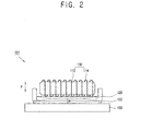
- FIG. 2 is a side view illustrating the inductor apparatus in FIG. 1, which generates vibrations.
- an inductor apparatus 101 includes an inductor 110, a supporting member 120 and a substrate 130.
- the inductor 110 includes a core 112 formed in a circular loop shape, and a coil 114 winding the core 112.
- the inductor 110 is supported to the supporting member 120 to be mounted on the substrate 130.
- the inductor 110 is applied with current from the substrate 130 to perform a predetermined function.
- the supporting member 120 supports the inductor 110 on a surface thereof.
- a supporting pin 122 supports the supporting member 120 to the substrate 130.
- Other circuit elements (not illustrated) are mounted on the substrate 130.
- noises and vibrations may be caused by an electromagnetic force generated from the inductor 110 according to variation of current.
- a magnetic field is formed to have a direction "B.”
- an electromagnetic force is generated to have a direction "F” to the coil 114.
- the electromagnetic force generated to the coil 114 is transferred to the core 112, and to the supporting member 120. Accordingly, referring to "a" in FIG. 2, the electromagnetic force having the direction "F” causes vibration to the supporting member 120.
- the vibration of the supporting member 120 is transferred to the substrate 130 and the circuit elements mounted thereon, and thereby damages or deforms the substrate 130 and the circuit elements.
- an electromagnetic force generated to the coil 114 may cause vibration having an audio frequency, and thereby causes noises.
- the present general inventive concept provides an inductor apparatus, a circuit board and an electronic device using the same, which is capable of minimizing noises and vibrations.
- an inductor apparatus including an inductor having a core formed in a loop shape to form a hollow part, and a coil winding the core, and a supporting member including a supporting surface supporting the core to face the hollow part, and a vibration preventing hole formed to correspond to the hollow part of the core.
- the core can be formed in a circular shape, and the vibration preventing hole can be formed in a circular shape to have the same center as the core.
- the core can be formed in a circular shape, and the vibration preventing hole can be formed in a regular polygonal shape to have the same center as the core.
- the core can be formed in one of a circular shape, an oval shape and a polygonal shape
- the vibration preventing hole can be formed in one of a circular shape, an oval shape and a polygonal shape.
- the core and the vibration preventing hole can have the same center.
- the vibration preventing hole can have a size to correspond to the hollow part.
- the inductor apparatus may further include a first vibration preventing member formed of an elastic material to be interposed between the core and the supporting member.
- the inductor apparatus may further include a substrate to which the supporting member is supported so that the inductor is mounted on the substrate, and a second vibration preventing member formed of an elastic material to be interposed between the supporting member and the substrate.
- the coil may include a PEW wire.
- the inductor apparatus may further include a substrate on which the inductor is mounted, wherein the supporting member includes a supporting pin extending from a circumference surrounding the supporting surface to be supported to the substrate.
- circuit board including a substrate, an inductor having a core formed in a loop shape to form a hollow part, and a coil winding the core, and a supporting member having a supporting surface supporting the core to face the hollow part and a vibration preventing hole formed to correspond to the hollow part of the core, and mounting the inductor on the substrate.
- the core can be formed in a circular shape, and the vibration preventing hole can be formed in a circular shape to have the same center as the core.
- the core can be formed in a circular shape, and the vibration preventing hole can be formed in a regular polygonal shape to have the same center as the core.
- the core can formed in one of a circular shape, an oval shape and a polygonal shape
- the vibration preventing hole can be formed in one of a circular shape, an oval shape and a polygonal shape.
- the core and the vibration preventing hole can have the same center.
- the vibration preventing hole can have a size to correspond to the hollow part.
- the circuit board can further include a first vibration preventing member formed of an elastic material to be interposed between the core and the supporting member.
- the circuit board can further include a second vibration preventing member formed of an elastic material to be interposed between the supporting member and the substrate.
- the coil can include a PEW wire.
- the supporting member can include a supporting pin extending from a circumference surrounding the supporting surface to be supported to the substrate.
- an electronic device including a circuit board, the circuit board including: a substrate; an inductor having a core formed in a loop shape to form a hollow part, and a coil winding the core, and a supporting member including a supporting surface supporting the core to face the hollow part and a vibration preventing hole formed to correspond to the hollow part of the core, and mounting the inductor on the substrate.
- an inductor assembly including an inductor including a loop-shaped core and a winding around the core; and a supporting member to support the inductor on one side thereof and including a hole in a center portion thereof to correspond with a center of the core.
- the supporting member can further include: at least one support pin extending extending from another side opposite the one side to connect with a substrate.
- the inductor assembly can further include: a first vibration preventing member disposed between the core and the supporting member to absorb vibrations therebetween; and a second vibration member disposed between the supporting member and the substrate to absorb vibrations therebetween.
- an inductor apparatus 1 includes an inductor 10 and a supporting member 20, and can be mounted on a substrate 30.
- the substrate 30 is installed in an electronic device (not illustrated) to perform a predetermined function.
- Other circuit elements may be mounted on the substrate 30.
- the substrate 30 may be provided as an image signal generating driving part installed in a TV, or other circuit boards including the inductor 10.
- the electronic device may be provided as a TV, audio equipment or other electronic devices including the inductor 10.
- the inductor 10 includes a core 12 formed in a loop shape to have a hollow part 13, and a coil 14 winding around the core 12.
- the core 12 is formed in a circular loop shape to form the hollow part 13, but alternatively, the core 12 may be formed in a polygonal loop shape, such as a rectangular loop shape or the like, or in a curved loop shape such as an oval loop shape or the like.
- the core 12 can be formed to be a closed loop, but alternatively, opposite ends of the core 12 may be distanced from each other as long as inner and outer areas thereof can be distinguishably formed.
- the core 12 is formed in phenolic resins or other plastics, or in iron or other metals.
- the coil 14 winds around the core 12 to have a predetermined inductance, and is electrically connected to the substrate 30.
- the coil 14 generates an induced electromotive force based on variation of current supplied from the substrate 30.
- the coil 14 can wind all over the core 12 to have a predetermined pitch. Accordingly, an electromagnetic force generated from the respective parts of the core 12 can be balanced, and thereby minimize vibrations.
- the coil 14 may wind around a part of the core 12, or the coil 14 may wind around the core 12 to have a different pitch.
- the coil 14 can be provided as a PEW wire, which has one wire. Thus, vibration of the supporting member 20 can be minimized.
- the coil 14 may be provided as a LITZ wire, which has a plurality of wires twisted around each other.
- the coil 14 can be liquid impregnated with an insulating varnish.
- the supporting member 20 includes a supporting surface 22 to support the core 12 and to face the hollow part 13. That is, the supporting member 20 supports the inductor 10 so that an axis (O) extending through the center of the core 12 is perpendicular to a planar direction of the supporting surface 22 of the supporting member 20.
- the supporting member 20 includes a vibration preventing hole 24 formed through a center portion to correspond with the hollow part 13 of the core 12.
- the vibration preventing hole 24 can be formed in a circular shape to have the same center as the core 12 (referring to O in FIG. 3). That is, the vibration preventing hole 24 can be formed co-axially with the core 12. Accordingly, vibration of the supporting member 30 by means of an electromagnetic force generated to the coil 14 can be symmetrical with respect to the center thereof, and thereby minimize vibrations.
- the vibration preventing hole 24 has a size to correspond with the hollow part 13.
- the vibration preventing hole 24 can have a maximized size as long as the supporting member 20 remains strong enough to support the core 12.
- the diameter of the vibration preventing hole 24 may be the same as the inside diameter of the core 12.
- the vibration preventing hole 24 can be formed in a circular shape, but alternatively, the vibration preventing hole 24 may be formed in a regular polygonal shape, a polygonal shape, an oval shape, a curved shape or other shapes as long as it is formed to correspond with the hollow part 13.
- the supporting member 20 includes at least one supporting pin 26.
- the supporting pin(s) 26 extends from a circumference 23 surrounding the supporting surface 22 to be supported to the substrate 30.
- the supporting pin(s) 26 extends from an opposite side of the supporting member 20 with respect to the supporting surface 22, and couples the supporting member 20 to the substrate 30, and to thereby mount the inductor 10 on the substrate 30.
- the supporting pin(s) 26 may extend from a part of the supporting member 20 to correspond to the supporting surface 22.
- the supporting pin(s) 26 may be omitted in view of an alternate mounting means.
- the supporting member 20 may be supported to the substrate 30 by an adhesive or other coupling members.
- the inductor apparatus 1 can minimize vibration caused by an electromagnetic force generated to the coil 14.
- an electromagnetic force F is generated to be transferred to the core 12 and to the supporting member 20 through the supporting surface 22, and to vibrate the supporting member 20. That is, the supporting member 20 stores vibration energy, and becomes a medium for vibration.
- the amplitude of vibration may be at a maximum in the center of the supporting member 20 corresponding to the hollow part 13.
- the vibration energy stored in the supporting member 20 may be transferred to the substrate 30, and accordingly, the supporting member 20 may collide with the substrate 30 and generate noises.
- the supporting member 20 includes the vibration preventing hole 24 corresponding to the hollow part 13, vibration of the supporting member 20 can be reduced (refer to "a" in FIG. 4 to illustrate vibrations), and storage of vibration energy can be prevented. Accordingly, noises and vibrations caused by the electromagnetic force can be minimized.
- the supporting member 20 having the vibration preventing hole 24 can efficiently minimize noises and vibrations.
- the inductor apparatus 1 includes a first vibration preventing member 40 interposed between the core 12 and the supporting member 20 and can be formed of an elastic material.
- the first vibration preventing member 40 may be respectively adhered to the core 12 and the supporting surface 22 by an adhesive.
- the first vibration preventing member 40 may be formed of rubber or a plastic material having elasticity.
- the first vibration preventing member 40 prevents vibration from being transferred from the core 12 to the supporting member 20.
- the first vibration preventing member 40 may be omitted as necessary.
- the inductor apparatus 1 includes a second vibration preventing member 50 interposed between the supporting member 20 and the substrate 30 and formed of an elastic material.
- the second vibration preventing member 50 may be adhered to the supporting member 20 by an adhesive.
- the second vibration preventing member 50 may be formed of the same material as the first vibration preventing member 40, or the second vibration preventing member 50 may be formed of rubber or a plastic material having an elasticity.
- the second vibration preventing member 50 prevents vibration from being transferred from the supporting member 20 to the substrate 30.
- the second vibration preventing member 50 may be omitted as necessary.
- a circuit board includes a substrate 30, an inductor 10, and a supporting member 20.
- the inductor 10 includes a core 12 formed in a loop shape to form a hollow part 13 and a coil 14 winding the core 12.
- the supporting member 20 includes a supporting surface 22 to support the core 12 to face the hollow part 13, and a vibration preventing hole 24 formed to correspond with the hollow part 13.
- the supporting member 20 mounts the inductor 10 on the substrate 30.
- the inductor apparatus, the circuit board, and the electronic device using the same according to the present general inventive concept can minimize noises and vibrations caused by an electromagnetic force generated to the coil of the inductor according to variation of current.
Landscapes
- Engineering & Computer Science (AREA)
- Power Engineering (AREA)
- Microelectronics & Electronic Packaging (AREA)
- Coils Or Transformers For Communication (AREA)
Applications Claiming Priority (1)
| Application Number | Priority Date | Filing Date | Title |
|---|---|---|---|
| KR1020050127904A KR20070066561A (ko) | 2005-12-22 | 2005-12-22 | 인덕터장치, 회로기판 및 이를 이용한 전자기기 |
Publications (2)
| Publication Number | Publication Date |
|---|---|
| EP1801822A2 true EP1801822A2 (de) | 2007-06-27 |
| EP1801822A3 EP1801822A3 (de) | 2009-08-05 |
Family
ID=37963934
Family Applications (1)
| Application Number | Title | Priority Date | Filing Date |
|---|---|---|---|
| EP06077082A Withdrawn EP1801822A3 (de) | 2005-12-22 | 2006-11-23 | Induktorvorrichtung, Leiterplatte, und elektonisches Gerät, welches diese nutzt |
Country Status (4)
| Country | Link |
|---|---|
| US (1) | US7868722B2 (de) |
| EP (1) | EP1801822A3 (de) |
| KR (1) | KR20070066561A (de) |
| CN (1) | CN1996518A (de) |
Families Citing this family (6)
| Publication number | Priority date | Publication date | Assignee | Title |
|---|---|---|---|---|
| KR101111189B1 (ko) * | 2010-07-14 | 2012-02-15 | 주식회사 아모그린텍 | 인덕터 단자대 및 이를 이용한 인덕터 장치 |
| US9136050B2 (en) * | 2010-07-23 | 2015-09-15 | Cyntec Co., Ltd. | Magnetic device and method of manufacturing the same |
| JP2013201377A (ja) * | 2012-03-26 | 2013-10-03 | Panasonic Corp | リアクトル装置 |
| US10049808B2 (en) * | 2014-10-31 | 2018-08-14 | Samsung Electro-Mechanics Co., Ltd. | Coil component assembly for mass production of coil components and coil components made from coil component assembly |
| US10172237B1 (en) * | 2017-08-28 | 2019-01-01 | Osram Sylvania Inc. | Space-efficient PCB-based inductor |
| EP3933861A1 (de) * | 2020-07-03 | 2022-01-05 | Eltek AS | Verfahren zur herstellung eines cm- oder dm-induktors sowie cm- oder dm-induktor |
Family Cites Families (26)
| Publication number | Priority date | Publication date | Assignee | Title |
|---|---|---|---|---|
| GB603309A (en) | 1944-10-12 | 1948-06-14 | Patelhold Patentverwertung | Improvements in bodies of powdered magnetic material of high permeability |
| US3290635A (en) | 1964-02-07 | 1966-12-06 | Westinghouse Electric Corp | Damped magnetic cores |
| JPS57170519U (de) * | 1981-04-20 | 1982-10-27 | ||
| DE3340985C2 (de) * | 1983-11-10 | 1986-06-12 | Kurt 1000 Berlin Kazubek | Vorrichtung zur Halterung von Ringkern-Transformatoren und -Drosseln |
| DE3440985A1 (de) | 1984-11-09 | 1986-05-15 | German 8700 Würzburg Gresser | Orthopaedisch optimierter fahrzeugsitz |
| US4612246A (en) | 1985-03-21 | 1986-09-16 | Westinghouse Electric Corp. | Lubricated polyester enameled electrical conductors |
| US4623865A (en) | 1985-05-09 | 1986-11-18 | General Electric Company | Current transformer arrangement for ground fault circuit interrupters |
| US4754250A (en) * | 1985-08-05 | 1988-06-28 | Firma Wilhelm Sedlbauer Gmbh | Holding device for toroidal cores provided with windings |
| JPH01243407A (ja) * | 1987-11-26 | 1989-09-28 | Matsushita Electric Works Ltd | チョークコイル |
| FR2679377B1 (fr) | 1991-07-18 | 1995-03-17 | Mecagis | Dispositif d'amortissement mecanique d'un tore magnetique dans un boitier. |
| JPH0661062A (ja) * | 1992-08-06 | 1994-03-04 | Fujitsu Ltd | ノイズ除去素子 |
| JPH0897575A (ja) | 1994-09-26 | 1996-04-12 | Nec Kansai Ltd | 高周波回路実装構体およびその製造方法 |
| JPH08138944A (ja) * | 1994-11-11 | 1996-05-31 | Fuji Electric Co Ltd | 有鉄心環状コイルの固定具 |
| JP3097485B2 (ja) * | 1995-02-03 | 2000-10-10 | 株式会社村田製作所 | チョークコイル |
| US5675121A (en) * | 1995-06-05 | 1997-10-07 | Pulse Engineering, Inc. | Precision graphics foil header |
| JPH09148141A (ja) * | 1995-11-28 | 1997-06-06 | Mitsui Petrochem Ind Ltd | ケース収納型磁心 |
| US5706358A (en) * | 1996-07-26 | 1998-01-06 | Ashworth; William J. | Magnetic audio transducer with hinged armature |
| JPH11186049A (ja) | 1997-12-19 | 1999-07-09 | Taiyo Yuden Co Ltd | 可変リニアリティコイル |
| CN1277625C (zh) * | 1998-02-06 | 2006-10-04 | 并木精密宝石株式会社 | 电磁式驱动器及其安装构造 |
| JP2000223363A (ja) | 1999-01-28 | 2000-08-11 | Matsushita Electric Ind Co Ltd | 電子部品およびこれを実装する配線基板 |
| JP4472097B2 (ja) | 2000-03-28 | 2010-06-02 | 北芝電機株式会社 | 直流モータのブラシ防振構造 |
| JP3794928B2 (ja) | 2000-04-17 | 2006-07-12 | 東京精電株式会社 | 低騒音・低損失リアクトル |
| US6642827B1 (en) * | 2000-09-13 | 2003-11-04 | Pulse Engineering | Advanced electronic microminiature coil and method of manufacturing |
| JP3900030B2 (ja) * | 2002-07-11 | 2007-04-04 | 東海ゴム工業株式会社 | 能動型ダイナミックダンパ |
| US6912133B2 (en) * | 2002-07-22 | 2005-06-28 | Magnetic Design Labs Inc. | Ruggedized inverter chassis |
| US7598837B2 (en) * | 2003-07-08 | 2009-10-06 | Pulse Engineering, Inc. | Form-less electronic device and methods of manufacturing |
-
2005
- 2005-12-22 KR KR1020050127904A patent/KR20070066561A/ko not_active Withdrawn
-
2006
- 2006-11-22 US US11/562,664 patent/US7868722B2/en not_active Expired - Fee Related
- 2006-11-23 EP EP06077082A patent/EP1801822A3/de not_active Withdrawn
- 2006-12-13 CN CNA2006101669901A patent/CN1996518A/zh active Pending
Also Published As
| Publication number | Publication date |
|---|---|
| CN1996518A (zh) | 2007-07-11 |
| KR20070066561A (ko) | 2007-06-27 |
| EP1801822A3 (de) | 2009-08-05 |
| US7868722B2 (en) | 2011-01-11 |
| US20070146108A1 (en) | 2007-06-28 |
Similar Documents
| Publication | Publication Date | Title |
|---|---|---|
| JP6715101B2 (ja) | 振動発電機、振動発電ユニット、振動発電モジュールおよび電気機器 | |
| CN102078857B (zh) | 线性振动器 | |
| TW459124B (en) | Vibration actuator having an elastic member between a suspension plate and a magnetic circuit device | |
| US8786144B2 (en) | Linear vibration motor | |
| US20140132089A1 (en) | Linear vibration motor | |
| US20120169148A1 (en) | Linear vibration motor | |
| US20110266892A1 (en) | Vibration generating device | |
| US9025796B2 (en) | Vibration generator | |
| US8742634B2 (en) | Linear vibration motor | |
| US11778386B2 (en) | Sound production device and electronic apparatus therefor | |
| US20170126109A1 (en) | Vibration motor | |
| US20110062801A1 (en) | Linear vibrator | |
| US6023518A (en) | Electromagnetic sound generator | |
| US7868722B2 (en) | Inductor apparatus, circuit board, and electronic device using the same | |
| US8933597B2 (en) | Linear vibration motor | |
| KR20010098828A (ko) | 다기능 바이브레이션 액추에이터 | |
| JP2013118308A (ja) | トランスおよびスイッチング電源装置 | |
| US20120146433A1 (en) | Linear vibrator | |
| JP2951561B2 (ja) | 電子機器用コイル部品 | |
| US6114934A (en) | Variable linearity coil | |
| CN111724979A (zh) | 线圈部件和电子装置 | |
| US7034756B2 (en) | Antenna coil device | |
| KR20120101797A (ko) | 진동 발생기 | |
| KR102066662B1 (ko) | 진동 모터 | |
| US9030274B2 (en) | Filter assembly |
Legal Events
| Date | Code | Title | Description |
|---|---|---|---|
| PUAI | Public reference made under article 153(3) epc to a published international application that has entered the european phase |
Free format text: ORIGINAL CODE: 0009012 |
|
| AK | Designated contracting states |
Kind code of ref document: A2 Designated state(s): AT BE BG CH CY CZ DE DK EE ES FI FR GB GR HU IE IS IT LI LT LU LV MC NL PL PT RO SE SI SK TR |
|
| AX | Request for extension of the european patent |
Extension state: AL BA HR MK YU |
|
| RIN1 | Information on inventor provided before grant (corrected) |
Inventor name: LEE, SANG-HOON Inventor name: CHO, JIN-HYUN Inventor name: OH, PIL-YONG Inventor name: KANG, JEONG-IL Inventor name: HWANG, SUNG-HO |
|
| PUAL | Search report despatched |
Free format text: ORIGINAL CODE: 0009013 |
|
| AK | Designated contracting states |
Kind code of ref document: A3 Designated state(s): AT BE BG CH CY CZ DE DK EE ES FI FR GB GR HU IE IS IT LI LT LU LV MC NL PL PT RO SE SI SK TR |
|
| AX | Request for extension of the european patent |
Extension state: AL BA HR MK RS |
|
| AKX | Designation fees paid | ||
| REG | Reference to a national code |
Ref country code: DE Ref legal event code: 8566 |
|
| STAA | Information on the status of an ep patent application or granted ep patent |
Free format text: STATUS: THE APPLICATION IS DEEMED TO BE WITHDRAWN |
|
| 18D | Application deemed to be withdrawn |
Effective date: 20100206 |