EP1801912B1 - Procédé pour la fabrication d'un support d'antenne - Google Patents
Procédé pour la fabrication d'un support d'antenne Download PDFInfo
- Publication number
- EP1801912B1 EP1801912B1 EP05027921A EP05027921A EP1801912B1 EP 1801912 B1 EP1801912 B1 EP 1801912B1 EP 05027921 A EP05027921 A EP 05027921A EP 05027921 A EP05027921 A EP 05027921A EP 1801912 B1 EP1801912 B1 EP 1801912B1
- Authority
- EP
- European Patent Office
- Prior art keywords
- tube
- clamp
- widened
- outer tube
- starting
- Prior art date
- Legal status (The legal status is an assumption and is not a legal conclusion. Google has not performed a legal analysis and makes no representation as to the accuracy of the status listed.)
- Expired - Lifetime
Links
Images







Classifications
-
- H—ELECTRICITY
- H01—ELECTRIC ELEMENTS
- H01Q—ANTENNAS, i.e. RADIO AERIALS
- H01Q1/00—Details of, or arrangements associated with, antennas
- H01Q1/12—Supports; Mounting means
- H01Q1/1207—Supports; Mounting means for fastening a rigid aerial element
- H01Q1/1221—Supports; Mounting means for fastening a rigid aerial element onto a wall
-
- H—ELECTRICITY
- H01—ELECTRIC ELEMENTS
- H01Q—ANTENNAS, i.e. RADIO AERIALS
- H01Q1/00—Details of, or arrangements associated with, antennas
- H01Q1/12—Supports; Mounting means
Definitions
- the invention relates to a method for producing an antenna holder and to a method for producing a component set for an antenna holder mountable with the component set with the features according to the preamble of claim 1.
- Such a method is from the German utility model DE 202 19 274 U1 known.
- This document discloses an antenna holder with a mounting base, an antenna mast and holding means for attaching the antenna mast to the mounting base.
- the mounting base comprises two intermeshing tubes, an outer tube and an inner tube.
- the holding means are formed by a clamp and a counter-clamp, which can be connected to one another by a screw connection such that the clamp and the counter-clamp clamp a portion of the mounting base between their clamp inner sides. More details on the production of the mounting base can be found in the utility model DE 202 19 274 U1 do not remove.
- the invention has for its object to provide a cost-effective method of manufacturing an antenna holder, are reliably avoided in the unwanted movements or vibrations of the mounting base after installation of the antenna holder, for example on a roof of a housing.
- the invention provides that at least one of the two tubes is widened with the aid of a Aufweitwerkmaschinees before the inner tube is inserted into the outer tube.
- a significant advantage of the invention is to be seen in the fact that it is possible due to the expansion step, very cost-effective to achieve a quasi-optimal adaptation of the outer diameter of the inner tube to the inner diameter of the outer tube.
- the method according to the invention can be resorted to standard tubes with standard dimensions, ie with a standard inner diameter or standard outer diameter; because an adaptation of the inner tube to the outer tube and / or vice versa according to the invention by a separate expansion step. It is therefore not necessary in the method according to the invention to resort to custom-made or custom-made tubes for the production of the antenna holder, but inexpensive standard material can be used.
- Another important advantage of the invention is that due to the expansion step, a quasi arbitrarily precise adjustment of the inner tube to the outer tube or vice versa can be done so that the two tubes can slide into each other in the ideal case completely free of play.
- Such a backlash makes it possible to achieve a particularly high stability of the antenna holder after a roof installation, so that even strong gusts of wind can not cause appreciable oscillations in the interior of the mounting base.
- the antenna holder thus has a particularly high mechanical stability.
- the expansion of the tube is preferably carried out with a mandrel whose outer diameter is greater than the inner diameter of the tube to be expanded, by the mandrel is driven through the tube, whereby the inner diameter and, consequently, the outer diameter of the tube is increased.
- the expansion of the inner tube can for example, in the context of a so-called calibration step.
- the widening of the tube (s) preferably takes place in a range between 1/10 mm (0.1 mm) and 3/10 mm (0.2 mm) - based on the inner diameter of the respective tube.
- the expansion is about 2/10 mm (0.2 mm).
- the outer diameter of the finished manufactured inner tube corresponds to the inner diameter of the finished manufactured outer tube such that the two tubes without play, at least approximately backlash-free, is displaceable.
- a starting tube is used for producing the outer tube, the inner diameter of which is too small for the inner tube to be inserted, it is considered advantageous if the starting tube is widened with the aid of the widening tool and the formation of an expanded starting tube and the outer tube is formed with the expanded starting tube becomes.
- the outer tube is still coated after widening, for example with a rust protection layer, it is considered advantageous if the starting tube is widened such that the inner diameter of the widened output tube corresponds to the outer diameter of the inner tube plus a predetermined tolerance value plus twice the coating thickness of the respective coating corresponds, which is still applied to the inside of the expanded output tube after performing the Aufweit suitses.
- the inner tube is still coated after widening, for example with a rust protection layer, it is considered advantageous if the starting tube is widened such that the outer diameter of the widened output tube reduces the inner diameter of the outer tube minus a predetermined tolerance value and less twice the coating thickness of the respective coating corresponds, which is still applied to the outside of the expanded output tube after performing the Aufweit suitses.
- a rust-preventive layer for example, a chromium layer or a zinc layer, in particular by hot-dip galvanizing, be applied to the expanded starting tube, be it the outer tube or the inner tube.
- the antirust layer preferably has a thickness between 5/100 mm (0.05 mm) to 12/100 mm (0.12 mm).
- a clamp and a counter-clamp for mounting the antenna mast are made, wherein the clamp and / or the clamp is made of a different, harder material than the outer tube, the inner sides of the clamp during assembly of the Clamp the antenna mast.
- An advantage of this embodiment of the method is the fact that due to the different materials for the clamp and / or counter clamp on the one hand and the clamped portion of the mounting base on the other hand during tightening the screw to an at least slight deformation or deformation of the mounting base by the harder and concomitantly material-related "stable" clamp / counter clamp, whereby the clamped portion of the mounting base, for example, the outer tube of the mounting base, to the shape of the clamp / counter-clamp when attaching the screw, at least slightly adjusted.
- the mounting base loses on its outer side its previously existing shape, preferably its rotational symmetry, so that subsequent rotation of the antenna mast relative to the mounting base is made more difficult or, in the ideal case, completely impossible.
- the mounting base can still be made very stable; because the deformation is not achieved by a constructive weakening of the mounting base (eg by a particularly thin outer tube), but instead by a harder clamp / counter-clamp material.
- a constructive weakening of the mounting base eg by a particularly thin outer tube
- a harder clamp / counter-clamp material e.g., a harder clamp / counter-clamp material.
- when tightening the screw connection such an intimate connection between the clamp / counter clamp and the mounting base is caused that it is very similar to a welded connection; So it is a kind of "cold welding" performed when tightening the screw.
- the stability of the antenna holder is significantly improved overall, so that the installation of even larger antennas with even larger cross-sectional areas and wind loads than previously possible.
- a particularly strong and thus suitable material for an antenna holder for example, steel, so that it is considered advantageous if the clamp, the counter-clamp and the mounting base are made of steel, for the clamp and / or for the clamp a harder steel grade than is selected for the mounting base.
- suitable materials include stainless steel, plastic, glass fiber reinforced plastic or aluminum.
- a harder material is selected for the clamp and / or the counter clamp than for the mounting base.
- the mounting base is made of plastic, for example, a harder plastic, a glass fiber reinforced plastic, aluminum, steel or stainless steel can be used as the material for the clamp and / or counter clamp. Passes the mounting base For example, from glass fiber reinforced plastic, it can be used as a material for the clamp and / or clamp a harder glass fiber reinforced plastic, aluminum, steel or stainless steel. If the mounting base is made of aluminum, preference is given to steel or stainless steel for the clamp and / or counter clamp. The same applies to other material combinations.
- the clamp and the counter-clamp and the outer tube of the mounting base are dimensioned such that the clamped outer tube is at least on the outer wall side, for example, both the outer wall side and inner wall side, deformed by a proper tightening the screw.
- the inner tube and the outer tube are clamped together in such a way that they are fixed relative to one another. This additional jamming significantly increases the stability of the mounting base.
- the clamp and / or the counter-clamp are provided with projections which are pressed when tightening the screw into the mounting base and deform it.
- the clamp is provided with projections, and the counter clamp has a smooth clamp inside.
- the smooth inner side of the clamp is formed by a gutter part, which is held by at least two U-shaped holding elements.
- the two U-shaped holding elements can, for example, at their two ends in each case with a thread be fitted to which nuts are screwed to form the screw and for securing the holding means to the mounting base.
- the gutter part has a curvature which is adapted to the outer diameter of the portion of the mounting base clamped by the clamp and the counter-clamp.
- the mounting base is provided with fastening elements by means of which it can be fastened on two adjacent rafters or roof battens.
- the outer wall side of the mounting base, in particular that of the outer tube is - at least in the section which is provided for fastening the clamp / clamp - in cross-section preferably round or polygonal designed to allow any or virtually arbitrary adjustment angle of the antenna mast relative to the mounting base.
- the clamp and the counter clamp are dimensioned so small that an attachment of the antenna mast to the mounting base is possible even after mounting the mounting base on rafters or roof battens.
- the counter clamp is preferably made smaller than the clamp because the counter clamp must find space "below” the mounting base in the roof area.
- small in this context means that the counter clamp in the radial direction - seen from the mounting base - a smaller maximum distance from the mounting base than the clamp.
- the foot of the antenna mast is preferably attached directly to the clamp outer side of the clamp, for example glued, screwed or welded.
- a clamp which is formed by a U-profile is particularly stable, light and thus advantageous.
- the side walls of the U-profile preferably have two mutually opposite recesses for receiving the mounting base.
- the contour of the recesses is preferably formed in multiple stages, wherein protrusions are formed by the steps of the contour, which are pressed when tightening the screw in the mounting base and deform it.
- FIGS. 1 . 1A . 1B and 1C to 9 For the sake of clarity, the same reference signs are used for identical or comparable components.
- FIG. 1 is an embodiment of an antenna holder 10 - not shown to scale for clarity - shown.
- the antenna holder 10 has an antenna mast 20, which is fastened by means of holding means 30 to a mounting base 40 of the antenna holder 10.
- the longitudinal direction of the antenna mast 20 extends along the Y direction and the mounting base 40 is oriented in the X direction with respect to its longitudinal direction. It should be mentioned in this context that the antenna mast 20 via the holding means 30 is pivotally attached to the mounting base so that it can be pivoted in the plane defined by the Y and Z directions with respect to the mounting base 40.
- the mounting base 40 has an inner tube 50, with its in the FIG. 1 right end 60 is inserted into an outer tube 70 of the mounting base 40.
- An Indian FIG. 1 left end 80 of the inner tube 50 is attached to a fastener 90 in the form of an angle or T-profile.
- the fastening element 90 has holes 100 with which the fastening element 90 can be screwed to a rafter of a roof.
- the holes 100 of the fastener 90 are offset in the X direction, to avoid that when screwing the fastener 90 on a timber rafters splitting of the roof rafter can occur.
- the arrangement of the holes 100 in the fastening element 90 is preferably symmetrical to the center M of the fastening element 90.
- the outer diameter d of the inner space 50 is adapted very precisely to the inner diameter D of the outer tube 70; Due to this adaptation of the two diameters d and D is achieved that the inner tube 50 can be moved largely free of play and "rattle-free" in the outer tube 70.
- the relative position of the inner tube 50 in the outer tube 70 is determined by a fixing screw 110 which is screwed by means of a thread 120 in the outer tube 70, whereby a fixing or fixing of the position of the inner tube 50 within the outer tube 70 is achieved.
- the holding means 30 have a clamp 150 which cooperates with a counter-clamp 160.
- the counter-clamp 160 has two holding elements 170 and 180, each with threads 190 are fitted and screwed by means of nuts 200 to the clamp 150.
- the counter-clamp 160 also has a gutter part 210 which, after tightening the two holding elements 170 and 180 on the clamp 150, rests against a section 220 of the outer tube 70 on the outer wall side.
- a further fastening element 250 can be seen, which is attached to the outer tube 70, for example, welded.
- the further fastening element 90 is preferably likewise a T or angled profile as in the case of the fastening element 90.
- the further fastening element 250 is likewise provided with holes 100, which allow a tightening of the further fastening element 250 on a rafter.
- the arrangement of the holes 100 in the further fastening element 250 is preferably symmetrical to the center M of the fastening element 250 in the longitudinal direction L.
- the inner tube 50 and the outer tube 70 are attached to the two fastening elements 90 and 250 offset.
- the center axis M1 of the inner tube 50 is not aligned with the center M of the fastening element 90 in the longitudinal direction L, but is offset by an offset V.
- the center axis M2 of the outer tube 70 offset by an offset V relative to the center M of the fastener 250 - seen in the longitudinal direction L.
- the offset V respectively forms a shorter attachment section L1 and a longer attachment section L2.
- the attachment point P - this is the center of the section at which the two tubes 50 and 70 are respectively attached to its fastening element - thus has in each case a distance from the center M of the fastener, which corresponds to the offset V.
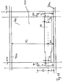
- the mounting base 40 of the antenna holder 10 is shown in a forward view after being mounted on a pitched roof 700.
- rafters 710 which extend obliquely downwards or upwards at the angle of inclination of the roof and battens 720, which are bolted to the rafters 710 and transverse to the rafters and thus extend horizontally.
- battens 720 which are bolted to the rafters 710 and transverse to the rafters and thus extend horizontally.
- the mounting base 40 is screwed onto the rafters 710. It can be seen that the mounting base 40 is mounted such that the shorter mounting portion L1 faces the lower roof batten 720a. The longer attachment portion L2 faces the upper batten 720b.
- the distance A1 of the mounting base to the lower batten 720a can be made very small, so that a maximum distance A2 between the mounting base and the upper batten 720b is achieved; Specifically, a distance A2 greater by the offset V is possible than if the two tubes 50 and 70 were mounted centrally on their two fastening elements 90 and 250. Due to the arrangement of the mounting base remote from the upper roof batten 720b, it is possible, even with very pointed roofs, to mount the antenna mast 20 (cf. FIG. 1 ) to pivot to a vertical position without the antenna mast 20 previously abuts against the upper roof batten 720b.
- FIG. 1B shows an embodiment of a device 800 with a expansion tool in the form of a mandrel 805, with which pipes, such as the outer tube 70 and / or the inner tube 50 according to the FIG. 1 , expand or widen the inner tube side, in order to achieve an optimal adaptation of the tube diameters to one another.
- the mandrel 805 which may have the shape of a straight circular cone or a truncated cone for the expansion in the cross-section round tubes, for example, has a maximum outer diameter Dk1.
- This outer diameter Dk1 of the mandrel 805 is larger than the inner diameter Div of an output tube 810, which is expanded and the outer tube 70 according to the FIG. 1 should be processed further.
- the mandrel 805 is forced through the exit tube 810 under the application of a mechanical force F, the inside diameter Div and outside diameter Dav of the exit tube 810 expand FIG. 1B for reasons of clarity only shown schematically.
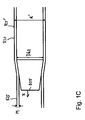
- the inner tube 50 according to the FIG. 1 edit (cf. Figure 1C ).
- the Figure 1C shows a second output tube 825, the expanded and the inner tube 50 according to the FIG. 1 should be processed further.
- expansion of the tubes 810 and 825 shown can be otherwise performed regardless of how the cross section of the tubes is formed.
- An expansion is possible with any cross-sections, for example in round, oval or even polygonal (triangular, square, pentagonal, etc.) cross sections; Of course, the cross-section of the expansion tool or mandrel 805 is to be selected accordingly.
- the antenna mast 20 and the clamp 150 are shown again in detail in a side view. It can be seen that the antenna mast 20 with its mast base 300 is attached to the outside 310 of the clip 150, for example glued, screwed or welded.
- the Clamp 150 is a U-profile with two side walls 320 and 330, which are arranged parallel to each other, at least approximately parallel to each other. The two side walls 320 and 330 are interconnected by a connecting part 340 that extends along the X direction.
- the clamp 150 is shown in a cross section.
- the side wall 330 according to FIG. 2 is provided with such a recess 350, wherein the two recesses of the two side walls 320 and 330 are aligned along the X direction.
- the recess 350 has a contour 360 which is provided with a plurality of steps 370.
- steps 370 projections 380 are formed, which are pressed in an attachment of the clamp 150 in the outer wall of the outer tube 70.
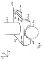
- the clamp 150 is shown in a three-dimensional representation. You can see the two side walls 320 and 330 and the two recesses 350 in the two side walls.
- the connecting part 340 is shown, which holds the two side walls 320 and 330 spaced from each other and connects to each other.
- FIG. 4 With a dashed line is in the FIG. 4 the outer tube 70 according to FIG. 1 represented, on which the clamp 150 is attached.
- Holes 400 through which in the FIG. 1 already mentioned holding elements 170 and 180 can be passed through the connecting part 340 and secured by means of the nuts 200.
- FIG. 5 is the counter clamp 160 according to FIG. 1 shown in a view from above. You can see the gutter part 210 as well the two holding elements 170 and 180, with which the gutter part 210 is screwed to the clamp 150.
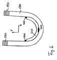
- the counter-clamp 160 is shown in a cross section. It can be seen that the retaining member 170 is attached by means of welds, of which in the FIG. 6 By way of example, three welds are designated by the reference numeral 410.
- the holding elements 170 and 180 are formed by U-shaped bent rods, which are provided at their ends in each case with the thread 190.
- FIG. 7 shows the counter clamp 160 again in a three-dimensional representation. It can be seen the gutter part 210, which is curved so that its inner side 420 is adapted to the outer diameter of the outer tube 70, so that the gutter part 210 fits after mounting on the outer tube 70 to this fitting.
- FIG. 8 the outer tube 70 and the inner tube 50 located therein are shown in a cross section. It can be seen that the outer diameter d of the inner tube 50 corresponds to the inner diameter D of the outer tube 70 very well, so that the inner tube 50 in the outer tube 70 is rattle-free and play-free displacement.
- the outer tube 70 is shown after the clamp 150 and the counter-clamp 160 have been mounted. It can be seen that the outer tube 70 is deformed by the shape of the side walls 320 and 330 of the clamp 150. Specifically, the protrusions 380 of the contour 360 of the two side walls 320 and 330 press (see. FIG. 3 ) in the outer wall 500 of the outer tube 70 and deform the outer tube 70 at least on the outer wall side to form dents 510. It may also come to an inner wall-side deformation of the outer tube 70, so that the inner tube 50 is clamped in the outer tube 70 and can not move in this. A deformation of the inner tube 50 may occur, but does not have to.
- the stability of the antenna holder 10 is significantly increased, because in addition to the fixation by the fixing screw 110 according to FIG. 1 now also a further fixation of the outer tube 70 with the inner tube 50 by the holding means 30 takes place.
- the material of the clamp 150 and the material of the counter-clamp 160 is harder than the material of the outer tube 70
- both the outer tube 70 and the clamp 150 and the counter-clamp 160 are made of steel; however, a harder steel grade than the outer tube 70 is selected for the clamp 150 and the opposing clamp 160.
- clamp 150 and the counter-clamp 160 are, for example, stainless steel, plastic, glass fiber reinforced plastic or aluminum.
- outer tube 70 a material from this group of materials is preferably also used, but the clamp and / or the counter-clamp should be made of a harder material than the outer tube 70, at least in its attachment portion 220th
Landscapes
- Support Of Aerials (AREA)
- Lining Or Joining Of Plastics Or The Like (AREA)
- Mutual Connection Of Rods And Tubes (AREA)
- Details Of Aerials (AREA)
Claims (12)
- Procédé de fabrication d'un support (10) d'antenne ou de fabrication d'un ensemble de composants pour un support d'antenne apte à être monté à l'aide de l'ensemble de composants, avec une base de montage (40) qui comprend au moins un tube intérieur (50) et un tube extérieur (70),
le tube extérieur (70) et le tube intérieur (50) étant fabriqués dans le procédé de telle sorte que le diamètre extérieur (d) du tube intérieur (50) soit plus petit que le diamètre intérieur (D) du tube extérieur (70) et que le tube intérieur puisse coulisser dans le tube extérieur,
caractérisé en ce que
au moins l'un des deux tubes (50, 70) est évasé à l'aide d'un outil d'évasement (805) avant que le tube intérieur soit inséré dans le tube extérieur. - Procédé selon la revendication 1, caractérisé en ce que l'évasement du ou des tubes est réalisé à l'aide d'un mandrin (805) dont le diamètre extérieur (Dk1, Dk2) est plus grand que le diamètre intérieur (Div) du tube (810, 815) à évaser en faisant passer le mandrin dans le tube, ce qui agrandit le diamètre intérieur et le diamètre extérieur du tube.
- Procédé selon la revendication 2, caractérisé en ce que l'évasement s'effectue dans le cadre d'une étape de calibrage.
- Procédé selon les revendications précédentes, caractérisé en ce que l'étape d'évasement est réalisée de telle sorte que le diamètre extérieur (d) du tube intérieur (50) corresponde au diamètre intérieur (D) du tube extérieur (70) pour que le tube intérieur puisse coulisser sans jeu et au moins approximativement sans jeu dans le tube extérieur.
- Procédé selon l'une des revendications précédentes, caractérisé en ce que pour fabriquer le tube extérieur (70), on utilise un tube de départ (810) dont le diamètre intérieur (Div) est trop petit pour le tube intérieur (50) qui doit y être inséré, en ce que le tube de départ est évasé à l'aide de l'outil d'évasement pour former un tube de départ (810') évasé et en ce que le tube extérieur (70) est formé avec le tube de départ (810') évasé.
- Procédé selon la revendication 5, caractérisé en ce que le tube de départ (810) est évasé de telle sorte que le diamètre intérieur (Din) du tube de départ (810') évasé corresponde au diamètre extérieur (d) du tube intérieur (50) plus une valeur prédéterminée de tolérance (Tw) et plus le double de l'épaisseur (Bs) d'un revêtement qui est encore appliqué sur le côté intérieur (810) du tube de départ (810') évasé après la réalisation de l'étape d'évasement.
- Procédé selon l'une des revendications 1 à 4 qui précèdent, caractérisé en ce que pour fabriquer le tube intérieur (50), on utilise un tube de départ (825) dont le diamètre extérieur est trop petit pour le tube extérieur (70),
en ce que le tube de départ est évasé à l'aide de l'outil d'évasement pour former un tube de départ (825') évasé et
en ce que le tube intérieur (50) est formé avec le tube de départ évasé. - Procédé selon la revendication 7, caractérisé en ce que le tube de départ (825) est évasé de telle sorte que le diamètre extérieur (d') du tube de départ (825') évasé corresponde au diamètre intérieur (D) du tube extérieur (70) diminué d' une valeur prédéterminée de tolérance (Tw) et diminué du double de l'épaisseur (Bs) d'un revêtement qui est encore appliqué sur le côté extérieur (830) du tube de départ (825') évasé après la réalisation de l'étape d'évasement.
- Procédé selon l'une des revendications 6 ou 8 qui précèdent, caractérisé en ce que comme revêtement, on applique une couche de protection antirouille et en particulier une couche de chrome ou de zinc.
- Procédé selon l'une des revendications précédentes, caractérisé en ce que l'on fabrique un collier de serrage (150) et un collier de serrage complémentaire de fixation d'un mât d'antenne, le collier de serrage et/ou le collier de serrage complémentaire (160) étant réalisés en un autre matériau plus dur que celui du tube extérieur que les côtés intérieurs des colliers de serrage serrent lors du montage du mât de l'antenne.
- Procédé selon la revendication 10, caractérisé en ce que le collier de serrage, le collier de serrage complémentaire et/ou la base de montage sont réalisées en matière synthétique, en matière synthétique renforcée de fibres de verre, en aluminium, en acier ou en acier inoxydable.
- Procédé selon l'une des revendications 10 ou 11 qui précèdent, caractérisé en ce que le collier de serrage et le collier de serrage complémentaire ainsi que le tube extérieur de la base de montage sont dimensionnés de telle sorte qu'un serrage correct d'une liaison vissée déforme au moins le côté extérieur du tube extérieur serré.
Priority Applications (3)
| Application Number | Priority Date | Filing Date | Title |
|---|---|---|---|
| EP05027921A EP1801912B1 (fr) | 2005-12-20 | 2005-12-20 | Procédé pour la fabrication d'un support d'antenne |
| DE502005004476T DE502005004476D1 (de) | 2005-12-20 | 2005-12-20 | Verfahren zum Herstellen eines Antennenhalters |
| AT05027921T ATE398844T1 (de) | 2005-12-20 | 2005-12-20 | Verfahren zum herstellen eines antennenhalters |
Applications Claiming Priority (1)
| Application Number | Priority Date | Filing Date | Title |
|---|---|---|---|
| EP05027921A EP1801912B1 (fr) | 2005-12-20 | 2005-12-20 | Procédé pour la fabrication d'un support d'antenne |
Publications (2)
| Publication Number | Publication Date |
|---|---|
| EP1801912A1 EP1801912A1 (fr) | 2007-06-27 |
| EP1801912B1 true EP1801912B1 (fr) | 2008-06-18 |
Family
ID=35705349
Family Applications (1)
| Application Number | Title | Priority Date | Filing Date |
|---|---|---|---|
| EP05027921A Expired - Lifetime EP1801912B1 (fr) | 2005-12-20 | 2005-12-20 | Procédé pour la fabrication d'un support d'antenne |
Country Status (3)
| Country | Link |
|---|---|
| EP (1) | EP1801912B1 (fr) |
| AT (1) | ATE398844T1 (fr) |
| DE (1) | DE502005004476D1 (fr) |
Family Cites Families (5)
| Publication number | Priority date | Publication date | Assignee | Title |
|---|---|---|---|---|
| DE1577111A1 (de) * | 1966-02-10 | 1970-02-19 | Siemens Ag | Verfahren zur Herstellung einer gleitenden Verbindung zwischen gegeneinander verschiebbaren Teilen |
| DE7606386U1 (de) * | 1976-03-03 | 1977-02-24 | Allendorfer Fabrik Fuer Stahlverarbeitung Ing. Herbert Panne Kg, 6331 Allendorf | Vorrichtung zum aufweiten von rohrenden |
| DE29714098U1 (de) * | 1997-08-07 | 1997-11-27 | Korflür, Reinhold, 59067 Hamm | Dachhalterung für eine Antenne |
| DE10262260B4 (de) | 2001-12-11 | 2013-04-18 | Hans Georg Engbarth | Antennenhalter |
| DE10258148B4 (de) * | 2001-12-11 | 2008-05-21 | Hans Georg Engbarth | Antennenhalter |
-
2005
- 2005-12-20 EP EP05027921A patent/EP1801912B1/fr not_active Expired - Lifetime
- 2005-12-20 DE DE502005004476T patent/DE502005004476D1/de not_active Expired - Lifetime
- 2005-12-20 AT AT05027921T patent/ATE398844T1/de active
Also Published As
| Publication number | Publication date |
|---|---|
| EP1801912A1 (fr) | 2007-06-27 |
| ATE398844T1 (de) | 2008-07-15 |
| DE502005004476D1 (de) | 2008-07-31 |
Similar Documents
| Publication | Publication Date | Title |
|---|---|---|
| DE10357844B4 (de) | Befestigungssystem | |
| DE102013021885B4 (de) | Vorrichtung zur Befestigung eines Fensters oder einer Tür in einer Wandöffnung und Verfahren zum Einbau eines Fensters oder einer Tür in eine Wandöffnung | |
| WO2020084143A1 (fr) | Système d'habillage de paroi, arrangement du système d'habillage et procédé pour le montage du système d'habillage | |
| EP2237365A2 (fr) | Support d'antennes | |
| EP2913536B1 (fr) | Support d'antennes | |
| EP0447936B1 (fr) | Dispositif pour la fixation d'éléments d'installation | |
| DE3440012A1 (de) | Vorrichtung zur halterung von masten fuer aussenantennen | |
| EP3951114B1 (fr) | Dispositif de fixation | |
| DE10018658B4 (de) | Rundschalungsmodul | |
| EP1770823B1 (fr) | Support pour une antenne | |
| EP1801912B1 (fr) | Procédé pour la fabrication d'un support d'antenne | |
| DE102007022459B4 (de) | Antennenhalter und Verfahren zu dessen Befestigung | |
| DE102005047898A1 (de) | Antennenhalter und Verfahren zu dessen Befestigung | |
| WO2003004793A2 (fr) | Structure d'ancrage pour toit | |
| EP1965077B1 (fr) | Support de générateur de toit pour éolienne | |
| EP1088943A2 (fr) | Support de montage avec accessoire de montage | |
| DE102006027173B4 (de) | Antennenhalter | |
| DE102005007114B4 (de) | Masthalter | |
| DE102007022597A1 (de) | Dachgeneratorträger für Windgeneratoren | |
| EP3316395B1 (fr) | Dispositif de fixation et son procédé de fabrication | |
| EP3268556B1 (fr) | Élément de fixation et système de fixation pour fixer des panneaux composites, notamment pour des éléments de façade | |
| WO2020007633A1 (fr) | Renforcement de pièce de robinetterie pour un évier et procédé pour soutenir une pièce de robinetterie au niveau d'un évier | |
| EP1365084B1 (fr) | Revêtement ajouré pour parties de bâtiment composé de barres à section circulaire | |
| EP3239537B1 (fr) | Dispositif de fixation et son procede de fabrication | |
| DE60314090T9 (de) | Befestigungssystem |
Legal Events
| Date | Code | Title | Description |
|---|---|---|---|
| PUAI | Public reference made under article 153(3) epc to a published international application that has entered the european phase |
Free format text: ORIGINAL CODE: 0009012 |
|
| 17P | Request for examination filed |
Effective date: 20060303 |
|
| AK | Designated contracting states |
Kind code of ref document: A1 Designated state(s): AT BE BG CH CY CZ DE DK EE ES FI FR GB GR HU IE IS IT LI LT LU LV MC NL PL PT RO SE SI SK TR |
|
| AX | Request for extension of the european patent |
Extension state: AL BA HR MK YU |
|
| GRAP | Despatch of communication of intention to grant a patent |
Free format text: ORIGINAL CODE: EPIDOSNIGR1 |
|
| GRAS | Grant fee paid |
Free format text: ORIGINAL CODE: EPIDOSNIGR3 |
|
| AKX | Designation fees paid |
Designated state(s): AT CH DE LI |
|
| GRAA | (expected) grant |
Free format text: ORIGINAL CODE: 0009210 |
|
| AK | Designated contracting states |
Kind code of ref document: B1 Designated state(s): AT CH DE LI |
|
| REF | Corresponds to: |
Ref document number: 502005004476 Country of ref document: DE Date of ref document: 20080731 Kind code of ref document: P |
|
| REG | Reference to a national code |
Ref country code: CH Ref legal event code: NV Representative=s name: PETER RUTZ Ref country code: CH Ref legal event code: EP |
|
| PLBE | No opposition filed within time limit |
Free format text: ORIGINAL CODE: 0009261 |
|
| STAA | Information on the status of an ep patent application or granted ep patent |
Free format text: STATUS: NO OPPOSITION FILED WITHIN TIME LIMIT |
|
| 26N | No opposition filed |
Effective date: 20090319 |
|
| REG | Reference to a national code |
Ref country code: CH Ref legal event code: PCAR Free format text: NEW ADDRESS: ALPENSTRASSE 14 POSTFACH 7627, 6302 ZUG (CH) |
|
| PGFP | Annual fee paid to national office [announced via postgrant information from national office to epo] |
Ref country code: DE Payment date: 20241231 Year of fee payment: 20 |
|
| PGFP | Annual fee paid to national office [announced via postgrant information from national office to epo] |
Ref country code: AT Payment date: 20241213 Year of fee payment: 20 |
|
| PGFP | Annual fee paid to national office [announced via postgrant information from national office to epo] |
Ref country code: CH Payment date: 20250101 Year of fee payment: 20 |
|
| REG | Reference to a national code |
Ref country code: CH Ref legal event code: H14 Free format text: ST27 STATUS EVENT CODE: U-0-0-H10-H14 (AS PROVIDED BY THE NATIONAL OFFICE) Effective date: 20251220 Ref country code: DE Ref legal event code: R071 Ref document number: 502005004476 Country of ref document: DE |
|
| REG | Reference to a national code |
Ref country code: AT Ref legal event code: MK07 Ref document number: 398844 Country of ref document: AT Kind code of ref document: T Effective date: 20251220 |