EP1802505B1 - Servofrein pneumatique - Google Patents
Servofrein pneumatique Download PDFInfo
- Publication number
- EP1802505B1 EP1802505B1 EP05801551A EP05801551A EP1802505B1 EP 1802505 B1 EP1802505 B1 EP 1802505B1 EP 05801551 A EP05801551 A EP 05801551A EP 05801551 A EP05801551 A EP 05801551A EP 1802505 B1 EP1802505 B1 EP 1802505B1
- Authority
- EP
- European Patent Office
- Prior art keywords
- control housing
- brake booster
- pneumatic brake
- booster
- ventilating
- Prior art date
- Legal status (The legal status is an assumption and is not a legal conclusion. Google has not performed a legal analysis and makes no representation as to the accuracy of the status listed.)
- Ceased
Links
Images

Classifications
-
- B—PERFORMING OPERATIONS; TRANSPORTING
- B60—VEHICLES IN GENERAL
- B60T—VEHICLE BRAKE CONTROL SYSTEMS OR PARTS THEREOF; BRAKE CONTROL SYSTEMS OR PARTS THEREOF, IN GENERAL; ARRANGEMENT OF BRAKING ELEMENTS ON VEHICLES IN GENERAL; PORTABLE DEVICES FOR PREVENTING UNWANTED MOVEMENT OF VEHICLES; VEHICLE MODIFICATIONS TO FACILITATE COOLING OF BRAKES
- B60T13/00—Transmitting braking action from initiating means to ultimate brake actuator with power assistance or drive; Brake systems incorporating such transmitting means, e.g. air-pressure brake systems
- B60T13/10—Transmitting braking action from initiating means to ultimate brake actuator with power assistance or drive; Brake systems incorporating such transmitting means, e.g. air-pressure brake systems with fluid assistance, drive, or release
- B60T13/24—Transmitting braking action from initiating means to ultimate brake actuator with power assistance or drive; Brake systems incorporating such transmitting means, e.g. air-pressure brake systems with fluid assistance, drive, or release the fluid being gaseous
- B60T13/46—Vacuum systems
- B60T13/52—Vacuum systems indirect, i.e. vacuum booster units
- B60T13/57—Vacuum systems indirect, i.e. vacuum booster units characterised by constructional features of control valves
Definitions
- the invention relates to a pneumatic brake booster for motor vehicles with an amplifier housing, which is divided by at least one, with a pneumatic differential pressure, axially movable wall in at least one working chamber and at least one vacuum chamber, with a, the differential pressure controlling, arranged in a control housing control valve Connection of the working chamber with the vacuum chamber or the atmosphere, which consists of two concentrically arranged sealing seats and an elastically deformable valve body, with an actuatable input member which is connected to a valve piston whose movement in the axial direction by an insertable into the control housing in the radial direction Cross member is limited, with an elastic reaction element, with an output member which acts on a master cylinder with an amplifying force, as well as with ventilation channels, which e are provided in the control housing and allow evacuation or venting of the working chamber.
- Such a pneumatic brake booster is for example from the DE 41 24 683 A1 known. This has in each case four ventilation channels, wherein a U-shaped cross member surrounds two diametrically opposed ventilation channels. As an improvement, the response and release behavior of the known brake booster is considered.
- the object is achieved in that two ventilation channels and two ventilation channels are provided in the control housing, which extend over an entire available circular cross-section of the control housing, and the ventilation channels are each interrupted by two webs for receiving the cross member.
- a further improvement of the response dynamics is achieved in that the ventilation channels extend in the axial direction approximately over the length of the venting channels. This considerably increases the flow cross-section of the ventilation channels. At the same time, the air flow is improved because the axial distance between the ventilation channels and the flow-critical region of the sealing seats of the control valve is optimally shortened.
- the ventilation channels are arranged symmetrically distributed diametrically opposite each other on a circumference of the control housing.
- Ventilation channels each extend over an angle of about 80 ° and the ventilation channels each extend over an angle of about 100 ° of the available circular cross-section of the control housing. This division has to be an optimal relationship between response and release dynamics proved.
- the webs are arranged distributed symmetrically within the one ventilation channel diametrically opposite to the webs of the second ventilation channel on the circumference of the control housing.
- the reaction element and a head flange of the output member are arranged in a sleeve which is designed substantially cylindrical and arranged on the control housing, so that the reaction element in the axial direction of the head flange on the one hand and the control housing and the On the other hand valve piston adjacent and rests in the radial direction of the sleeve. Furthermore, it is advantageous that thereby the gap extrusion of the reaction element in the transition region between the sleeve and the control housing can be minimized, which leads to damage of the reaction element.
- the sleeve has in an advantageous embodiment of the invention at its ends means for mounting improvement. These may be formed, for example, as a chamfer or as radially outwardly trained collar.
- the sleeve is advantageously fixed by means of a holding element in the axial direction, which is provided biased by a return spring of the brake booster, wherein the holding element simultaneously serves to guide the output member.
- An additional holding element for the sleeve is eliminated.
- connection channels and the ventilation channels of the control housing are offset by an angle of approximately 90 ° relative to the central axis thereof. This makes it possible to manufacture the control housing with up to four nests in the injection mold.
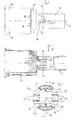
- Fig. 1 shows an embodiment of a pneumatic brake booster according to the invention in tandem design in longitudinal section, which comprises a booster housing 2 having a first housing half shell 3 and a second housing half shell, not shown, which are preferably pressed together by means of forming measures.
- the interior of the booster housing 2 is divided into a first, front, master cylinder-side booster chamber 6 and a second, rear brake pedal-side booster chamber 7 with the help of an approximately centrally arranged, fixed partition wall 5, wherein the partition wall 5 has a centrally disposed, circular recess 8, which is penetrated by a control housing 9 and its cylindrical extension 10.
- the partition wall 5 is sealingly attached to the extension 10 by means of a sealing element 11.
- the first, front booster chamber 6 is by a first movable wall 12 in a first vacuum chamber 14 of constant pressure and in a first working chamber 15 variable pressure and the second, rear booster chamber 7 through a second movable wall 13 in a second vacuum chamber 16 and a second working chamber 17 divided.
- the second, not shown, housing half shell is provided with a vacuum port, by means of which the first vacuum chamber 14 can be connected to a suitable vacuum source, such as an intake manifold of the motor vehicle engine, or to a vacuum pump.
- the first housing half-shell 3 is provided with an axial portion 19 of smaller diameter, in which the control housing 9 is guided axially movable sealed.
- a control valve 4 is provided, which is a allows controlled ventilation of the two working chambers 15,17 and thereby controls the pressure difference between the vacuum chambers 14,16 and the working chambers 15,17.
- the control valve 4 is actuated by an input member 18 which is connected to a brake pedal, not shown, and consists of a formed on the control housing 9 first sealing seat 20, one, formed on a connected to the input member 18 valve piston 22 second sealing seat 21 and a, with two sealing seats 20,21 cooperating valve body 23, which is pressed by means of a, supported on a guide member 24 valve spring 25 against the valve seats 20,21.
- the second working chamber 17 can be connected to the first vacuum chamber 14 via two ventilation channels 26 running laterally in the control housing 9.
- the braking force is transmitted via an end face on the control housing 9 fitting rubber-elastic reaction element 27 and a head flange 30 exhibiting output member 31 on an actuating piston of a master cylinder of the motor vehicle brake system, not shown, which is mounted on the vacuum side end of the brake booster 1.
- the input force applied to the input member 18 is transmitted to the reaction member 27 by means of the valve piston 22.
- a return spring 32 which is supported on the vacuum-side end wall of the booster housing 2, holds the movable walls 12,13 in the initial position shown.
- a return spring 33 is provided, which is arranged between a, arranged on the input member 18 holding member 34 and the guide member 24 of the control valve 4 and whose force provides a bias of the valve piston 22 and its valve seat 21 relative to the valve body 23.
- valve piston 22 The return movement of the valve piston 22 at the end of a braking operation is limited by a cross member 36 which is insertable in the radial direction in the control housing 9 and which rests in the release position of the brake booster shown in the drawing on the booster housing 2.
- the valve body 23 has a cooperating with the two sealing seats 20,21 annular sealing surface 37 which is stiffened by means of a metallic, L-shaped stiffening element 38 and provided with a plurality of axial passages 39.
- a pneumatic space 40 is limited.
- the flow channels formed by the passages 39 connect the pneumatic space 40 with an annular space 41 delimited by the sealing seats 20, 21, in which the afore-mentioned ventilation channels 35 open, so that the side of the valve body facing away from the sealing surface 37 23 trained pneumatic space 40 is constantly in communication with the second working chamber 17 and the valve body 23, a pressure compensation takes place.
- connection between the first and the second vacuum chambers 14,16 carried by one or more openings 28 in the extension 10 of the control housing 9, which are provided in the region between the partition wall 5 and the second movable wall 13.
- Connecting channels 42 are provided in the extension 10 of the control housing 9, which connect the first and the second vacuum chamber 14,16 together.
- two connection channels 42 are provided which extend in the axial direction from the second working chamber 17 to the first working chamber 15 and open radially into the first working chamber 15.
- a connecting channel 42 is formed in each case by axial side walls 43,49 and a radial side wall 44.
- Fig. 1 shows the brake booster 1 in a longitudinal section through two planes, the second connection channel 42 is not visible, however, the symmetrical structure of the brake booster 1 is clearly apparent from the figures described below.
- the reaction element 27 and the head flange 30 of the output member 31 are arranged in a cylindrical sleeve 29 which is arranged on the control housing 9 and which serves to avoid damage to the control housing, which may result from acting on the output member transverse forces.
- Fig. 1 the reaction element 27 adjacent in the axial direction on the one hand to the head flange 30 and on the other hand to the control housing 9 and the valve piston 22 at. In the radial direction, the reaction element 27 adjoins the sleeve 29. Due to the cylindrical configuration of the sleeve 29, the gap extrusion of the reaction element 27 in the transition region between the sleeve 29 and the control housing 9 is minimized, which can lead to damage of the reaction element 27. Furthermore, the sleeve 29 is easy to manufacture and thereby inexpensive.
- the sleeve 29 is fixed to the control housing 9 by a holding element 56, which in turn is biased by the return spring 32 of the brake booster 1.
- the holding element 56 an inner, axial, cylindrical extension 45 which serves to guide the output member 31 in the radial direction.
- the sleeve 29 has chamfers 46 at their ends.
- 29 may be provided radially outwardly formed collars at the ends of the sleeve.
- the second movable wall 13 is formed by a diaphragm plate 47 and an adjacent rolling diaphragm 48, the radially inner sealing bead 50 is clamped in a formed in the extension 10 of the control housing 9 annular groove 51 with the aid of a radially inwardly directed bias.
- the rolling diaphragm 48 has a desired kink point at which the rolling diaphragm 48 is folded on the control housing 9 after assembly.
- the resulting fold 52 allows a large bias of the Dichtwulstes 50 and at the same time ensures the investment of the rolling diaphragm 48 on the diaphragm plate 47. Due to the large radial bias of the rolling diaphragm 48, a small radial space of the interface control housing-diaphragm disc rolling diaphragm are possible, in particular one small radial depth of the annular groove 51, in which the sealing bead 50 is buttoned.
- the sealing bead 50 has an encircling sealing surface 53 on a lower side.
- the radially inner sealing bead 50 is designed such that it can tilt in the direction of the second working chamber 17, wherein the sealing surface 53 of a bottom of the annular groove 51 is lifted to allow a rapid pressure reduction from the second vacuum chamber 16 in the direction of working chamber 17 via the sealing bead 50.
- the sealing bead 50 Due to the tilting function of the sealing bead 50 can also in the case of a pressure surge from the side of the second vacuum chamber 16, which, for example, upon actuation of the brake booster 1 without vacuum in open Radniken or sudden withdrawal of a vacuum hose from the first vacuum chamber 14 of the brake booster 1 arise can, a Auskn adoptedn the rolling diaphragm 48 can be prevented and the pressure can be reduced in the direction of working chamber 17.
- Fig. 2 to 4 show various views and sections of the control housing 9 of the according to Fig. 1 described brake booster 1. It shows Fig. 2 a side view, Fig. 3 a cross section along in Fig. 2 shown line AA and Fig. 4 a longitudinal section along in Fig. 3 shown line BB.
- the ventilation channels 35 are each interrupted by two webs 54, which serve to receive, guide and fix the cross member 36.
- the webs 54 within the one aeration channel 35 are arranged symmetrically distributed diametrically opposite to the webs 54 within the second ventilation channel 35 on a circumference of the control housing 9.
- the ventilation channels 26,35 are arranged symmetrically distributed diametrically opposite each other on the circumference of the control housing 9.
- the two ventilation channels 26 each extend over an angle of about 80 ° and the two ventilation channels 35 each extend over an angle of about 100 ° of the available circular cross-section of the control housing 9.
- This division has proven to be the optimum ratio between response and release dynamics.
- the ventilation channels 35 are interrupted only by a cross-section of the webs 54 which is as small as possible for stability.
- a possible large flow cross-section of the channels 26,35 is realized, which allows fast ventilation of the working chamber. This improves the response and release behavior of the brake booster 1, which depends on the speed of the ventilation and venting of the working chambers 15,17.
- the ventilation channels 35 have a radially extending outlet region, which is bounded by outer walls 55 of the ventilation channels 26.
- the ventilation channels 35 extend in the axial direction approximately over the length of the venting channels 26, whereby the flow cross section of the ventilation channels 35 is considerably increased. At the same time, the air flow is improved because the axial distance between the ventilation channels 35 and the flow-critical region of the sealing seats 20,21 of the control valve 4 is optimally shortened.
- the connecting channels 42 and the ventilation channels 35 are offset by an angle of approximately 90 ° relative to the central axis M arranged to each other. This makes a very economical production of the control housing 9 with up to four nests in the injection mold possible.
- the brake booster 1 according to the invention is shown as a tandem version. In principle, however, the invention is suitable for all pneumatic brake booster in tandem and single version.
Landscapes
- Engineering & Computer Science (AREA)
- Transportation (AREA)
- Mechanical Engineering (AREA)
- Braking Systems And Boosters (AREA)
Claims (11)
- Servofrein pneumatique (1) pour véhicule automobile
avec un boîtier de servofrein (2) qui est divisé par au moins une paroi (12, 13) axialement mobile et pouvant être sollicitée par une pression différentielle pneumatique, en au moins une chambre de travail (15, 17) et au moins une chambre sous dépression (14, 16),
avec une soupape de commande (4), disposée dans un boîtier de commande (9) et commandant la pression différentielle, pour la liaison de la chambre de travail (15, 17) avec la chambre sous dépression (14, 16) ou l'atmosphère, laquelle soupape de commande est constituée de deux sièges d'étanchéité (20, 21) disposés concentriquement l'un à l'autre ainsi que d'un corps de soupape (23) déformable élastiquement,
avec un organe d'entrée (18) pouvant être actionné, qui est relié à un piston de soupape (22) dont le mouvement dans la direction axiale est limité par un organe transversal (36) pouvant être introduit dans le boîtier de commande (9) dans la direction radiale,
avec un élément de réaction (27) élastique,
avec un organe de sortie (31) qui agit sur un cylindre principal avec une force d'amplification,
ainsi qu'avec des canaux d'aération et de purge d'air (35, 26) qui sont prévus dans le boîtier de commande (9) et permettent la mise à l'atmosphère ou la ventilation de la chambre de travail (15, 17),
caractérisé en ce que dans le boîtier de commande (9) sont prévus deux canaux de purge d'air (26) ainsi que deux canaux d'aération (35) qui s'étendent sur toute une section circulaire disponible du boîtier de commande (9), et les canaux d'aération (35) sont interrompus chacun par deux pontets (54) pour recevoir l'organe transversal (36). - Servofrein pneumatique (1) selon la revendication 1, caractérisé en ce que les canaux d'aération (35) s'étendent dans la direction axiale approximativement sur la longueur des canaux de purge d'air (26).
- Servofrein pneumatique (1) selon la revendication 2, caractérisé en ce que les canaux d'aération et de purge d'air (35, 26) sont disposés symétriquement répartis et diamétralement opposés sur un pourtour du boîtier de commande (9).
- Servofrein pneumatique (1) selon la revendication 3, caractérisé en ce que les canaux de purge d'air (26) s'étendent chacun sur un angle d'environ 80° et les canaux d'aération (36) s'étendent chacun sur un angle d'environ 100° de la section circulaire disponible du boîtier de commande (9).
- Servofrein pneumatique (1) selon la revendication 3 ou 4, caractérisé en ce que les pontets (54) à l'intérieur d'un canal d'aération (35) sont disposés symétriquement répartis et diamétralement opposés aux pontets (54) à l'intérieur du second canal d'aération (35), sur le pourtour du boîtier de commande (9).
- Servofrein pneumatique (1) selon la revendication 5, caractérisé en ce que l'élément de réaction (27) ainsi qu'une bride de tête (30) de l'organe de sortie (31) sont disposés dans une douille (29) qui est de forme sensiblement cylindrique et disposée sur le boîtier de commande (9), ce qui fait que l'élément de réaction (27) est adjacent dans la direction axiale d'une part à la bride de tête (30) et d'autre part au boîtier de commande (9) et au piston de soupape (22), et s'applique contre la douille (29), dans la direction radiale.
- Servofrein pneumatique (1) selon la revendication 6, caractérisé en ce que la douille cylindrique (29) présente à ses extrémités des moyens pour améliorer le montage.
- Servofrein pneumatique (1) selon la revendication 7, caractérisé en ce que la douille (29) est réalisée biseautée à ses extrémités.
- Servofrein pneumatique (1) selon la revendication 7, caractérisé en ce que la douille (29) présente à ses extrémités une collerette réalisée radialement vers l'extérieur.
- Servofrein pneumatique (1) selon la revendication 8 ou 9, caractérisé en ce que la douille (29) est fixée dans la direction axiale au moyen d'un élément de retenue (56) qui est prévu précontraint par un ressort de rappel (32) du servofrein (1), l'élément de retenue (56) servant en même temps à guider l'organe de sortie (31).
- Servofrein pneumatique (1) selon l'une quelconque des revendications précédentes, dans lequel le servofrein (1) est réalisé dans une construction tandem dont le volume intérieur est divisé à l'aide d'une cloison (5) en un premier compartiment de servofrein (6) et en un second compartiment de servofrein (7), la cloison (5) présentant un évidement (8) de forme circulaire, disposé au centre, qui est traversé par le boîtier de commande (9) et la cloison (5) s'applique, au moyen d'un élément d'étanchéité (11), de manière étanche contre le boîtier de commande (9), avec une première ainsi qu'une seconde paroi mobile (12, 13) qui divisent le premier compartiment de servofrein (6) en une première chambre sous dépression (14) et en une première chambre de travail (15), et le second compartiment de servofrein (7) en une seconde chambre sous dépression (16) et en une seconde chambre de travail (17), ainsi qu'avec un ou plusieurs canaux de liaison (42) entre la première chambre de travail (15) et la seconde chambre de travail (17) pour une compensation de la pression entre ces deux chambres (15, 17), caractérisé en ce que les canaux de liaison (42) et les canaux d'aération (35) du boîtier de commande (9) sont disposés décalés les uns par rapport aux autres d'un angle d'environ 90° par rapport à son axe médian (M).
Applications Claiming Priority (3)
| Application Number | Priority Date | Filing Date | Title |
|---|---|---|---|
| DE102004050581 | 2004-10-15 | ||
| DE102005047528A DE102005047528A1 (de) | 2004-10-15 | 2005-10-04 | Pneumatischer Bremskraftverstärker |
| PCT/EP2005/055085 WO2006042795A1 (fr) | 2004-10-15 | 2005-10-07 | Servofrein pneumatique |
Publications (2)
| Publication Number | Publication Date |
|---|---|
| EP1802505A1 EP1802505A1 (fr) | 2007-07-04 |
| EP1802505B1 true EP1802505B1 (fr) | 2008-03-19 |
Family
ID=35759193
Family Applications (1)
| Application Number | Title | Priority Date | Filing Date |
|---|---|---|---|
| EP05801551A Ceased EP1802505B1 (fr) | 2004-10-15 | 2005-10-07 | Servofrein pneumatique |
Country Status (4)
| Country | Link |
|---|---|
| US (1) | US7634960B2 (fr) |
| EP (1) | EP1802505B1 (fr) |
| DE (2) | DE102005047528A1 (fr) |
| WO (1) | WO2006042795A1 (fr) |
Families Citing this family (2)
| Publication number | Priority date | Publication date | Assignee | Title |
|---|---|---|---|---|
| JP4222382B2 (ja) | 2006-04-28 | 2009-02-12 | トヨタ自動車株式会社 | 車両制動装置 |
| FR2949739B1 (fr) * | 2009-09-07 | 2011-10-14 | Bosch Gmbh Robert | Piston d'actionneur de servofrein et servofrein equipe d'un tel piston. |
Family Cites Families (10)
| Publication number | Priority date | Publication date | Assignee | Title |
|---|---|---|---|---|
| JPS60108582U (ja) * | 1983-12-28 | 1985-07-23 | 自動車機器株式会社 | ブレ−キ倍力装置 |
| FR2587288B1 (fr) * | 1985-09-19 | 1987-11-27 | Bendix France | Servomoteur d'assistance au freinage comprenant une butee de plongeur de valve en fil metallique |
| DE4124683C2 (de) * | 1991-07-25 | 1998-07-09 | Teves Gmbh Alfred | Unterdruck-Bremskraftverstärker |
| US5245829A (en) * | 1992-09-02 | 1993-09-21 | General Motors Corporation | Brake booster with dual durometer rear bearing |
| JP3045027B2 (ja) * | 1994-12-28 | 2000-05-22 | ボッシュ ブレーキ システム株式会社 | 倍力装置における弁プランジャの抜止め構造 |
| DE19654271A1 (de) * | 1995-12-26 | 1997-07-03 | Aisin Seiki | Unterdruck-Kraftverstärker für eine Fahrzeugbremsanlage |
| FR2744086B1 (fr) | 1996-01-30 | 1998-08-14 | Alliedsignal Europ Services | Servomoteur pneumatique d'assistance au freinage a clapet perfectionne |
| FR2794090B1 (fr) | 1999-05-31 | 2001-08-31 | Delphi Tech Inc | Amplificateur de force de freinage perfectionne |
| US6584883B2 (en) * | 2001-10-09 | 2003-07-01 | Delphi Technologies, Inc. | Pneumatic brake booster |
| FR2855133B1 (fr) * | 2003-05-22 | 2005-07-15 | Bosch Gmbh Robert | Amplificateur a depression pour l'assistance au freinage d'un vehicule automobile comportant un siege de valve ameliore |
-
2005
- 2005-10-04 DE DE102005047528A patent/DE102005047528A1/de not_active Withdrawn
- 2005-10-07 DE DE502005003387T patent/DE502005003387D1/de not_active Expired - Lifetime
- 2005-10-07 US US11/665,199 patent/US7634960B2/en active Active
- 2005-10-07 WO PCT/EP2005/055085 patent/WO2006042795A1/fr not_active Ceased
- 2005-10-07 EP EP05801551A patent/EP1802505B1/fr not_active Ceased
Also Published As
| Publication number | Publication date |
|---|---|
| WO2006042795A1 (fr) | 2006-04-27 |
| US20070266849A1 (en) | 2007-11-22 |
| DE102005047528A1 (de) | 2006-05-04 |
| EP1802505A1 (fr) | 2007-07-04 |
| DE502005003387D1 (de) | 2008-04-30 |
| US7634960B2 (en) | 2009-12-22 |
Similar Documents
| Publication | Publication Date | Title |
|---|---|---|
| EP0420947B1 (fr) | Servofrein a depression pour vehicules a moteur | |
| DE3900416C2 (de) | Unterdruckbremskraftverstärker | |
| EP2331376B1 (fr) | Servofrein pneumatique | |
| EP2531387B1 (fr) | Servofrein | |
| DE4124683A1 (de) | Unterdruck-bremskraftverstaerker | |
| DE3018270C2 (fr) | ||
| DE4027562A1 (de) | Unterdruck-bremskraftverstaerker | |
| EP1802505B1 (fr) | Servofrein pneumatique | |
| EP0322524A1 (fr) | Servofrein en tandem pour véhicules à moteur | |
| DE102019208406A1 (de) | Bremssystemdämpfvorrichtung | |
| EP1910142B1 (fr) | Servofrein pneumatique et membrane destinee a ce servofrein | |
| EP0681539B1 (fr) | Servofrein a depression pour vehicules | |
| EP1802506B1 (fr) | Servofrein pneumatique | |
| EP0950595B1 (fr) | Ensemble soupape pour servofrein à vide | |
| EP2379387B1 (fr) | Amplificateur pneumatique de force de freinage pour un système de freinage d'un véhicule | |
| DE10054251A1 (de) | Unterdruck-Bremskraftverstärker | |
| DE19539601B4 (de) | Unterdruckbremskraftverstärker für Kraftfahrzeuge | |
| DE102005054758A1 (de) | Pneumatischer Bremskraftverstärker in Tandembauweise | |
| DE102019209892A1 (de) | Bremssystemdämpfvorrichtung mit einem weiteren Raum | |
| DE102006033534A1 (de) | Pneumatischer Bremskraftverstärker | |
| DE60302464T2 (de) | Unterdruckbremskraftverstärker | |
| DE60132219T2 (de) | Pneumatischer bremskraftverstärker und zugehöriges herstellungsverfahren | |
| DE102004014930B3 (de) | Tandem-Bremskraftverstärker mit Trennwandabstützung | |
| EP1655192B1 (fr) | Servofrein à dépression pour véhicules automobiles | |
| DE10308053A1 (de) | Unterdruckbremskraftverstärker |
Legal Events
| Date | Code | Title | Description |
|---|---|---|---|
| PUAI | Public reference made under article 153(3) epc to a published international application that has entered the european phase |
Free format text: ORIGINAL CODE: 0009012 |
|
| 17P | Request for examination filed |
Effective date: 20070515 |
|
| AK | Designated contracting states |
Kind code of ref document: A1 Designated state(s): DE FR |
|
| GRAP | Despatch of communication of intention to grant a patent |
Free format text: ORIGINAL CODE: EPIDOSNIGR1 |
|
| DAX | Request for extension of the european patent (deleted) | ||
| RBV | Designated contracting states (corrected) |
Designated state(s): DE FR |
|
| GRAS | Grant fee paid |
Free format text: ORIGINAL CODE: EPIDOSNIGR3 |
|
| GRAA | (expected) grant |
Free format text: ORIGINAL CODE: 0009210 |
|
| AK | Designated contracting states |
Kind code of ref document: B1 Designated state(s): DE FR |
|
| REF | Corresponds to: |
Ref document number: 502005003387 Country of ref document: DE Date of ref document: 20080430 Kind code of ref document: P |
|
| ET | Fr: translation filed | ||
| PLBE | No opposition filed within time limit |
Free format text: ORIGINAL CODE: 0009261 |
|
| STAA | Information on the status of an ep patent application or granted ep patent |
Free format text: STATUS: NO OPPOSITION FILED WITHIN TIME LIMIT |
|
| 26N | No opposition filed |
Effective date: 20081222 |
|
| REG | Reference to a national code |
Ref country code: FR Ref legal event code: PLFP Year of fee payment: 11 |
|
| REG | Reference to a national code |
Ref country code: FR Ref legal event code: PLFP Year of fee payment: 12 |
|
| REG | Reference to a national code |
Ref country code: FR Ref legal event code: PLFP Year of fee payment: 13 |
|
| REG | Reference to a national code |
Ref country code: FR Ref legal event code: PLFP Year of fee payment: 14 |
|
| REG | Reference to a national code |
Ref country code: DE Ref legal event code: R084 Ref document number: 502005003387 Country of ref document: DE |
|
| REG | Reference to a national code |
Ref country code: DE Ref legal event code: R081 Ref document number: 502005003387 Country of ref document: DE Owner name: CONTINENTAL AUTOMOTIVE TECHNOLOGIES GMBH, DE Free format text: FORMER OWNER: CONTINENTAL TEVES AG & CO. OHG, 60488 FRANKFURT, DE |
|
| PGFP | Annual fee paid to national office [announced via postgrant information from national office to epo] |
Ref country code: FR Payment date: 20221028 Year of fee payment: 18 |
|
| PGFP | Annual fee paid to national office [announced via postgrant information from national office to epo] |
Ref country code: DE Payment date: 20220531 Year of fee payment: 18 |
|
| REG | Reference to a national code |
Ref country code: DE Ref legal event code: R119 Ref document number: 502005003387 Country of ref document: DE |
|
| PG25 | Lapsed in a contracting state [announced via postgrant information from national office to epo] |
Ref country code: FR Free format text: LAPSE BECAUSE OF NON-PAYMENT OF DUE FEES Effective date: 20231031 Ref country code: DE Free format text: LAPSE BECAUSE OF NON-PAYMENT OF DUE FEES Effective date: 20240501 |