EP1803604A2 - Eisenbahndrehgestell ausgerüstet mit einem linearen Induktionsantrieb - Google Patents
Eisenbahndrehgestell ausgerüstet mit einem linearen Induktionsantrieb Download PDFInfo
- Publication number
- EP1803604A2 EP1803604A2 EP05028323A EP05028323A EP1803604A2 EP 1803604 A2 EP1803604 A2 EP 1803604A2 EP 05028323 A EP05028323 A EP 05028323A EP 05028323 A EP05028323 A EP 05028323A EP 1803604 A2 EP1803604 A2 EP 1803604A2
- Authority
- EP
- European Patent Office
- Prior art keywords
- cross
- induction motor
- linear induction
- members
- bogie
- Prior art date
- Legal status (The legal status is an assumption and is not a legal conclusion. Google has not performed a legal analysis and makes no representation as to the accuracy of the status listed.)
- Withdrawn
Links
- 230000006698 induction Effects 0.000 title claims abstract description 66
- 230000033001 locomotion Effects 0.000 claims abstract description 6
- 230000007246 mechanism Effects 0.000 claims description 23
- 238000000034 method Methods 0.000 claims description 16
- 239000000725 suspension Substances 0.000 claims description 16
- 238000006073 displacement reaction Methods 0.000 claims description 4
- 230000005540 biological transmission Effects 0.000 claims description 2
- 238000006243 chemical reaction Methods 0.000 description 14
- 238000004804 winding Methods 0.000 description 4
- 238000005259 measurement Methods 0.000 description 3
- 230000001133 acceleration Effects 0.000 description 1
- 238000005266 casting Methods 0.000 description 1
- 238000010276 construction Methods 0.000 description 1
- 210000003128 head Anatomy 0.000 description 1
- 239000002184 metal Substances 0.000 description 1
- 238000004321 preservation Methods 0.000 description 1
- 230000000717 retained effect Effects 0.000 description 1
Images
Classifications
-
- B—PERFORMING OPERATIONS; TRANSPORTING
- B61—RAILWAYS
- B61B—RAILWAY SYSTEMS; EQUIPMENT THEREFOR NOT OTHERWISE PROVIDED FOR
- B61B13/00—Other railway systems
- B61B13/12—Systems with propulsion devices between or alongside the rails, e.g. pneumatic systems
-
- B—PERFORMING OPERATIONS; TRANSPORTING
- B60—VEHICLES IN GENERAL
- B60L—PROPULSION OF ELECTRICALLY-PROPELLED VEHICLES; SUPPLYING ELECTRIC POWER FOR AUXILIARY EQUIPMENT OF ELECTRICALLY-PROPELLED VEHICLES; ELECTRODYNAMIC BRAKE SYSTEMS FOR VEHICLES IN GENERAL; MAGNETIC SUSPENSION OR LEVITATION FOR VEHICLES; MONITORING OPERATING VARIABLES OF ELECTRICALLY-PROPELLED VEHICLES; ELECTRIC SAFETY DEVICES FOR ELECTRICALLY-PROPELLED VEHICLES
- B60L13/00—Electric propulsion for monorail vehicles, suspension vehicles or rack railways; Magnetic suspension or levitation for vehicles
- B60L13/03—Electric propulsion by linear motors
- B60L13/035—Suspension of the vehicle-borne motorparts
-
- B—PERFORMING OPERATIONS; TRANSPORTING
- B60—VEHICLES IN GENERAL
- B60L—PROPULSION OF ELECTRICALLY-PROPELLED VEHICLES; SUPPLYING ELECTRIC POWER FOR AUXILIARY EQUIPMENT OF ELECTRICALLY-PROPELLED VEHICLES; ELECTRODYNAMIC BRAKE SYSTEMS FOR VEHICLES IN GENERAL; MAGNETIC SUSPENSION OR LEVITATION FOR VEHICLES; MONITORING OPERATING VARIABLES OF ELECTRICALLY-PROPELLED VEHICLES; ELECTRIC SAFETY DEVICES FOR ELECTRICALLY-PROPELLED VEHICLES
- B60L2200/00—Type of vehicles
- B60L2200/26—Rail vehicles
Definitions
- the invention relates to a railway bogie designed for propulsion by a linear induction motor, to an arrangement for mounting a linear induction motor to a bogie of a railway vehicle, in particular an arrangement equipped with an adjustment device for adjusting the height of the linear induction motor relative to a reaction rail. It also relates to a method for mounting a linear induction motor to a bogie of a railway vehicle, and to a method for adjusting the distance between the linear motor and the reaction rail.
- Linear inductors consisting of field windings placed above one or several reaction rails and supplied with poly-phase current producing a moving field between the field windings on the vehicle and the running surface of the rails are used in railway vehicles for providing electromagnetic brakes and/or linear motor propulsion units.
- correct and controllable operation of the electromagnetic brake or motor requires the preservation, during normal service, of a constant or nearly constant air gap between the field windings and the running surface of the reaction rail. This air gap is smaller for linear induction motors than for electromagnetic brakes, typically between 9 and 24 mm.
- a resilient supporting device for a railway linear motor is disclosed in US 3,516,364 .
- the field windings are attached to a rigid frame connecting the four axle boxes of a conventional bogie.
- the rigid frame consists of two longitudinal members whose ends rest on the four axle boxes of the wheel axles, and two cross members.
- Two inductors are located on each side of the longitudinal vertical mid plane of the bogie. Each inductor is supported via a series of lateral resilient studs on the longitudinal members. Additional longitudinal resilient studs are used to transmit longitudinal traction forces to the cross-members.
- the longitudinal frame members are attached to the axle boxes via means comprising a screw and nut connection for adjusting the vertical position of the longitudinal member with respect to the axle boxes.
- precise adjustment of the position of the frame and inductors proves difficult, since each of the four screw and nut connections simultaneously influences the roll and pitch angles of the frame.
- a steerable railway truck with a linear induction motor is known from US 4,440,092 .
- the truck is supported on four flanged wheels, whose wheel axles are rotationally retained in journal housings.
- the journal housings are secured to a front and a rear yoke, respectively.
- the truck is connected to the car body of the railway vehicle by means of a bolster and associated secondary suspension elements to support the car body.
- the front and rear yoke are articulated to the bolster to allow steering of the front and rear axles.
- the linear induction motor is supported relative to the yokes by means of a system of three vertical links, comprising one single link centrally positioned in the mid vertical longitudinal plane of the bogie to connect the linear motor unit to the outboard yoke and a pair of suspension links located on opposite sides and at equal distance of the mid vertical longitudinal plane of the bogie.
- a bogie with a linear induction motor is known from EP 0 102 551 .
- the bogie is provided with two wheel sets, each provided with a pair of axle boxes, a saddle casting fitted over each axle box to allow relative vertical motion between the axle box and the saddle, a bogie frame rigidly secured to the four saddle and a primary suspension between the interposed between the frame and the axle boxes.
- the axle on each wheel set is surrounded by a U-shaped beam supported at its ends on a pair of bearings located close to the wheels.
- Each beam is provided with one centrally located resilient universal joint for hanging one longitudinal end of an inductor of a linear induction motor. This arrangement does not provide any resilient suspension of the U-shape beams, and the bearings between the beams and the shaft experience high acceleration levels.
- the linear inductor motor is supported by two universal joints only and is free to roll about a longitudinal horizontal axis crossing the centres of the universal joints. This motion, however, is not acceptable when the air gap is small. Moreover, it is not possible to adjust the cross-level error of the linear inductor, i.e. the height difference between the left and right sides of the inductor, because the inductor is suspended from two points only spaced apart along the longitudinal centre axis of the vehicle.
- One object of the invention is to provide a bogie that allows very small air gaps between the linear inductor motor and the reaction rail.
- Another object of the invention is to provide a bogie that has a suspension optimised both for supporting a vehicle body and for the specific needs of a linear inductor.
- a railway bogie for supporting a car body of a railway vehicle comprising:
- the primary and secondary suspensions can be designed independently from the resilient mounting means for the linear induction motor suspension.
- Each of the three suspension systems can be optimised without being constrained by the others.
- the link means allow relative displacement between the linear induction motor and the cross-members in the thrust direction and the bogie further comprises a thrust transmission means for directly transmitting thrust between the linear induction motor and the bogie or the car body of the railway vehicle.
- the link means allow relative displacement between the linear induction motor and cross-members in a transverse direction of the bogie, the bogie further comprising lateral link means for directly transmitting lateral forces between the linear induction motor and the bogie or the car body of the railway vehicle.
- the link means include a set of three vertical link members for connecting the linear induction motor means to a first one of the two cross-members and consisting of a central link pivotally connected to the first cross-member longitudinally on one side of the first cross-member and a pair of left and right link members pivotally connected to the first cross-member on the other side of the first cross-member at two locations laterally spaced apart on opposite sides of the centre point of the first cross member and equidistant therefrom, the three link members being pivotally connected to the linear induction motor.
- the link means further comprise a set of two vertical link members pivotally connected to the linear induction motor and to the second cross-member at two locations longitudinally spaced apart on opposite sides of the axis of rotation of the second cross-member.
- the left and right mounting means comprise left and right height adjustment mechanisms for adjusting the distance between the cross-members and the axle boxes.
- Each height adjustment mechanism may comprise a first adjuster element provided with an internal thread, a second adjuster element provided with an external thread, one of the first and second adjuster elements being secured to the corresponding axle box and the other adjuster element being secured to the cross-member through a rubber spring.
- the adjustment mechanisms allow ready adjustment of the air gap between the reaction rail and the linear induction motor. More specifically, these mechanisms allow independent adjustment of the height, of the pitch angle and of the roll angle of the linear induction motor in relation to the reaction rail.
- a method for mounting a linear induction motor means to the bogie comprising a step of mounting the linear induction motor means to the first and second cross-members by means of the link means and a step of measuring the distance between the linear induction motor and the reaction rail at least three, preferably four locations, a step of assessing a cross level error based on the measured distances, and a step of operating the height adjustment mechanisms of the left and right mounting means of one of the cross-members based on the cross level error.
- a method for mounting a linear induction motor means to the bogie comprising a step of mounting the linear induction motor means to the first and second cross-members by means of the link means and a step of measuring the distance between the linear induction motor the reaction rail at least three, preferably four locations, a step of assessing a first height deviation from a predetermined desired height at a first longitudinal end of the inductor, and a second height deviation from the predetermined desired height at a second longitudinal end of the inductor, based on the measured distances, a step of operating the height adjustment mechanisms of the left and right mounting means close to the first longitudinal end of the linear induction motor based on the first height deviation; and a step of operating the height adjustment mechanisms of the left and right mounting means close to the second longitudinal end of the inductor based on the second height deviation.
- a method for mounting a linear induction motor means to the bogie comprising a step of mounting the linear induction motor means to the first and second cross-members by means of the link means and a step of measuring the distance between the linear induction motor the reaction rail at at least three, preferably four locations, a step of assessing a first height deviation from a predetermined desired height at a first longitudinal end of the inductor, and a second height deviation from the predetermined desired height at a second longitudinal end of the inductor, based on the measured distances, a step of assessing a cross level error based on the measured distances, a step of operating the height adjustment mechanisms of the left and right mounting means close to the first longitudinal end of the inductor based on the first height deviation; and a step of operating the height adjustment mechanisms of the left and right mounting means close to the second longitudinal end of the inductor based on the second height deviation and on the cross level error.
- a method for adjusting the position of a linear induction motor means mounted on a bogie as described hereinbefore comprising the steps of :
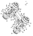
- the unsuspended part of a bogie 10 includes two wheel axles 12, 14 carrying the usual left and right track wheels 16. Each wheel axle 12, 14 is journalled in a pair of left and right axle boxes 18 located between the track wheels 16. Each axle box 18 is provided with front and rear pans 20 on which the lower end of a rubber spring 22 of the primary suspension seats.
- Each primary suspension spring 22 is screwed at its upper end to a spindle 24 that projects through a side bogie frame member 26 and is secured thereto, as illustrated in figure 2.
- the bogie frame 27 is provided with a pair of tubular transoms 28 and front and rear cross-members 30 welded to the side members 26.
- the vehicle body is supported on the bogie side members by an air spring assembly.
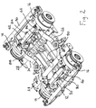
- the bogie is provided with a pair of cross-members 40, 42 for supporting the linear induction motor 44.
- Each cross-member 42, 44 extends above one of the wheel axles 12, 14 and is provided with two mounting eyes 46 at its ends.
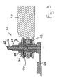
- each mounting eye 46 has a through hole and is sandwiched between an upper and a lower rubber spring 48, 50 of a resilient connection 52 to allow connection to the axle boxes 18.
- the rubber springs consist of a rubber body bonded to an upper and a lower rigid plate and are maintained on an adjuster sleeve 56 by a locking ring 58.
- the adjuster sleeve 56 is provided with an internal thread screwed on the external thread of an adjuster tube 60.
- the adjuster tube 60 cooperates at its axial inner ends with a mounting stud 62 in screwed on the axle box housing 64, so as to freely rotate about the stud axis without radial play.
- a hexagonal locknut 66 is screwed on the upper end of the stud 62 to prevent axial movement of the adjuster tube 60.
- a hexagonal locking nut 68 can be screwed on the adjuster tube 60 to lock the position of the adjuster sleeve 56.
- the rubber springs 48, 50 provide a stiff vertical suspension of each cross-members 40, 42 relative to the axle boxes 18, but have low rotational stiffness and allow the cross-members to rotate relative to a horizontal transversal axis 76 parallel to the axle 12, 14 and crossing the left and right studs 62 at a centre of rotation of the resilient connection 52.
- a system of five vertical links 80, 82, 84, 86, 88 support the inductor 44 relative to the cross-members.
- This system includes a pair of links 80, 82 centrally located at equal distance from the left and right mounting studs 62 on opposite sides of one of the cross-members 40.
- the system of vertical links also includes three vertical links 84, 86, 88 for connecting the inductor 44 to the other cross-member 42.
- the link 84 is located longitudinally on one side of the cross-member, at equal distance from the mounting studs 62, while the other two links 86, 88 are located longitudinally on the other side of the cross-member and are laterally spaced apart from one another at equal distance from the link 84.
- the five links are pivotally connected to the cross-members 40, 42 and to the inductor 44 through metal ball bearings. Thanks to these universal connections, the forces transmitted by the links to the cross-members are balanced and the point of application of the resultant force applied by the links on each cross-member is located on the rotation axis of the cross-member at equal distance from the mounting studs. This system of five links is therefore equivalent to a three-point levelling scheme.
- a longitudinal connecting rod 90 transmits the thrust forces directly from the inductor 44 to one of the transom tubes 28 of the bogie frame 27.
- Two lateral links 92 preferably located on the same side of the bogie, transmit lateral forces from the inductor 44 to one of the side members 26 of the bogie frame.
- Each pair of adjuster sleeve 56 and adjuster tube 60 constitutes a height adjuster integrated in the resilient connection 52, which can be accessed from above through an aperture in the floor of the car body and is operated as follows.
- the locking nut 68 is released and slacken by one or two turns.
- the locknut 66 is then released to allow free rotation of the threaded tube.
- a wrench can then be engaged on the hexagonal head of the threaded tube to turn it so as to raise or lower the adjuster sleeve as required. Once the desired position has been reached, the locknut is tightened and the locking nut is tightened.
- the four height adjusters are used to adjust the position of the cross-members in relation to the axle boxes and to the reaction rail on the ground.
- the height adjustment procedure is as follows: The bogie is first put on a section of track, which is both straight and level.
- the distance between the linear induction motor and the reaction rail is precisely measured at say four locations. Preferably, these locations are towards the outside edges of the inductor and in line with the cross-members.
- the measurement locations are symmetrical about the track centre line.
- the cross level error is determined for each longitudinal end of the inductor as the difference in height between the two measurement locations at the corresponding end of the inductor.
- An average cross level error is then determined as the average of the front and rear cross level errors.
- Adjustment of the cross level error can be made by adding half of the average cross level error to the low side of the inductor and subtracting half of the value from the high side, on cross-member 42. No adjustment needs to be made on the cross-member 40, since the corresponding end of the inductor is centrally mounted on the cross-member.
- the average height is determined at each longitudinal end of the inductor and the deviation from a predetermined nominal height is calculated. This error is the adjustment that needs to be made on the height adjusters of the corresponding cross-member.
- the cross level errors and the height error can be computed at the same time and the adjustments can be made in one step.
- the height measurement could be made at three locations instead of four, one central location close to cross-member 40 and two locations towards the ends of cross-member 42.
- the railway bogie described hereinbefore can be used with any kind of railway vehicle, alone or in pairs to carry a car body of any desired construction.
- suspension arrangement described above can be used to support a reaction plate of a linear induction motor, with the linear inductor being mounted in the guide rail for the vehicle.
- the universal connections of the links can be provided with stiff resilient means.
Landscapes
- Engineering & Computer Science (AREA)
- Transportation (AREA)
- Mechanical Engineering (AREA)
- Physics & Mathematics (AREA)
- Electromagnetism (AREA)
- Power Engineering (AREA)
- Chemical & Material Sciences (AREA)
- Combustion & Propulsion (AREA)
- Control Of Vehicles With Linear Motors And Vehicles That Are Magnetically Levitated (AREA)
- Railway Tracks (AREA)
Priority Applications (8)
| Application Number | Priority Date | Filing Date | Title |
|---|---|---|---|
| EP05028323A EP1803604A3 (de) | 2005-12-23 | 2005-12-23 | Eisenbahndrehgestell ausgerüstet mit einem linearen Induktionsantrieb |
| CN2011100063257A CN102114844B (zh) | 2005-12-23 | 2006-12-21 | 用于支撑轨道车辆车体的轨道转向架和相关方法 |
| US11/642,672 US7836830B2 (en) | 2005-12-23 | 2006-12-21 | Railway bogie provided with a linear induction motor |
| CN2006101712371A CN1986275B (zh) | 2005-12-23 | 2006-12-21 | 设有线性感应电机的轨道转向架 |
| CA 2571912 CA2571912C (en) | 2005-12-23 | 2006-12-21 | Railway bogie provided with a linear induction motor |
| JP2006348068A JP5248769B2 (ja) | 2005-12-23 | 2006-12-25 | リニア誘導モータを備える台車 |
| HK07113948.9A HK1105614B (en) | 2005-12-23 | 2007-12-20 | Railway bogie provided with a linear induction motor |
| HK11113261.2A HK1158584B (en) | 2005-12-23 | 2011-12-08 | Railway bogie for supporting a car body of a railway vehicle and related methods |
Applications Claiming Priority (1)
| Application Number | Priority Date | Filing Date | Title |
|---|---|---|---|
| EP05028323A EP1803604A3 (de) | 2005-12-23 | 2005-12-23 | Eisenbahndrehgestell ausgerüstet mit einem linearen Induktionsantrieb |
Publications (2)
| Publication Number | Publication Date |
|---|---|
| EP1803604A2 true EP1803604A2 (de) | 2007-07-04 |
| EP1803604A3 EP1803604A3 (de) | 2007-07-18 |
Family
ID=38038602
Family Applications (1)
| Application Number | Title | Priority Date | Filing Date |
|---|---|---|---|
| EP05028323A Withdrawn EP1803604A3 (de) | 2005-12-23 | 2005-12-23 | Eisenbahndrehgestell ausgerüstet mit einem linearen Induktionsantrieb |
Country Status (5)
| Country | Link |
|---|---|
| US (1) | US7836830B2 (de) |
| EP (1) | EP1803604A3 (de) |
| JP (1) | JP5248769B2 (de) |
| CN (2) | CN102114844B (de) |
| CA (1) | CA2571912C (de) |
Cited By (2)
| Publication number | Priority date | Publication date | Assignee | Title |
|---|---|---|---|---|
| WO2013135851A3 (fr) * | 2012-03-14 | 2014-06-26 | Alstom Transport Technologies | Voie ferree, vehicule ferroviaire pour circuler sur la voie ferree et ensemble comprenant la voie ferree et le vehicule ferroviaire |
| EP3636950A1 (de) * | 2018-10-08 | 2020-04-15 | Zhuzhou Times New Material Technology Co., Ltd. | Verfahren zur erhöhung der axialen steifheit, verringerung der radial- und biegesteifigkeit eines elastischen verbundbauteils |
Families Citing this family (17)
| Publication number | Priority date | Publication date | Assignee | Title |
|---|---|---|---|---|
| GB2430421A (en) * | 2005-09-22 | 2007-03-28 | Bombardier Transp Gmbh | Rail vehicle bogie |
| CN101565049B (zh) * | 2008-04-25 | 2011-06-08 | 南车青岛四方机车车辆股份有限公司 | 铰接构架直线电机转向架 |
| CN102079316B (zh) * | 2010-09-07 | 2012-08-08 | 南车青岛四方机车车辆股份有限公司 | 轨道车辆直线电机转向架及其制造方法 |
| CN102774395B (zh) * | 2011-05-11 | 2015-07-22 | 中国铁路总公司 | 驱动装置高度调整方法 |
| US9701319B2 (en) | 2013-08-12 | 2017-07-11 | Gonzalo Duran Ariza | Transportation systems |
| CN104973077B (zh) * | 2015-06-30 | 2017-10-31 | 中车青岛四方机车车辆股份有限公司 | 直线电机防脱落装置、高度调节方法、直线电机转向架 |
| CN105835898B (zh) * | 2016-03-26 | 2017-12-01 | 中车青岛四方机车车辆股份有限公司 | 一种转向架 |
| CA2936722C (en) * | 2016-07-19 | 2017-03-07 | Bombardier Transportation Gmbh | Bogie with a motor mount for a linear induction motor |
| CN107539324B (zh) * | 2017-09-14 | 2020-07-03 | 赵文明 | 一种水利水电工程用轮间距可调平板车 |
| GB2579190A (en) * | 2018-11-22 | 2020-06-17 | Bombardier Transp Gmbh | Running gear with a single pair of independent left and right wheels and lateral stop means, and associated low floor rail vehicle |
| CN110758412B (zh) * | 2019-10-11 | 2020-11-17 | 中车青岛四方机车车辆股份有限公司 | 直线电机转向架 |
| KR102479239B1 (ko) * | 2020-11-20 | 2022-12-20 | 현대로템 주식회사 | 철도차량용 림 대차 |
| CN112356868B (zh) * | 2020-12-07 | 2024-08-13 | 西南交通大学 | 一种用于轨道车辆转向架的铰接构架 |
| CN113895473B (zh) * | 2021-11-18 | 2022-08-26 | 中车长春轨道客车股份有限公司 | 适用于线性感应电机的转向架构架 |
| US20230191916A1 (en) * | 2021-12-20 | 2023-06-22 | Micah Skidmore | Novel electromagnetic propulsion and levitation technology |
| US20230399038A1 (en) * | 2022-03-15 | 2023-12-14 | Siemens Mobility, Inc. | Crossing gate mechanism with integrated cover or door detection scheme |
| CN115214725B (zh) * | 2022-07-14 | 2023-12-22 | 北京双泰气动设备有限公司 | 四轮卡轨随动恒定压力的牵引装置 |
Citations (3)
| Publication number | Priority date | Publication date | Assignee | Title |
|---|---|---|---|---|
| US3516364A (en) | 1967-12-28 | 1970-06-23 | Mte Soc | Resilient supporting device for a railway linear motor |
| EP0102551A2 (de) | 1982-08-09 | 1984-03-14 | Hitachi, Ltd. | Motorfahrzeugdrehgestell |
| US4440092A (en) | 1977-11-30 | 1984-04-03 | Urban Transportation Development Corporation Ltd. | Railway steering truck linear induction motor assembly |
Family Cites Families (24)
| Publication number | Priority date | Publication date | Assignee | Title |
|---|---|---|---|---|
| BE537731A (de) * | 1952-11-19 | |||
| US3602149A (en) * | 1969-03-28 | 1971-08-31 | Gen Steel Ind Inc | Linear motor driven railway vehicle truck |
| FR2052007A5 (de) | 1969-07-04 | 1971-04-09 | Creusot Forges Ateliers | |
| FR2159772A5 (de) * | 1971-11-12 | 1973-06-22 | Creusot Loire | |
| US3847089A (en) * | 1972-10-16 | 1974-11-12 | Ltv Aerospace Corp | Vehicle drive means |
| DE2443832A1 (de) * | 1974-09-13 | 1976-03-25 | Knorr Bremse Gmbh | Aufhaengevorrichtung fuer schienenbremsmagnete |
| JPS5628046A (en) * | 1979-08-14 | 1981-03-19 | Canadair Ltd | Assembled body of track truck and linear induction motor propeller |
| JPS58145565A (ja) * | 1982-02-24 | 1983-08-30 | 株式会社日立製作所 | リニアモ−タ推進台車 |
| JPS5948259A (ja) * | 1982-09-13 | 1984-03-19 | 株式会社日立製作所 | リニアモ−タ駆動車両用台車 |
| JPS5963262A (ja) * | 1982-10-01 | 1984-04-10 | 株式会社日立製作所 | リニアモ−タ推進台車 |
| JPS59106360A (ja) * | 1982-12-08 | 1984-06-20 | 株式会社日立製作所 | リニアモ−タの駆動台車 |
| JPS59164264A (ja) * | 1983-03-09 | 1984-09-17 | 住友金属工業株式会社 | 鉄道車両用リニアモ−タの塔載装置 |
| JPS59139458U (ja) * | 1983-03-09 | 1984-09-18 | 住友金属工業株式会社 | 鉄道車両用リニアモ−タのすき間調整機構 |
| JPS60121169A (ja) * | 1983-12-02 | 1985-06-28 | 株式会社日立製作所 | リニアモ−タ装架台車の牽引力伝達構造 |
| JPS62122863A (ja) * | 1985-11-22 | 1987-06-04 | 三菱重工業株式会社 | リニアモ−タ駆動車両用台車 |
| JPH01128453U (de) * | 1988-02-25 | 1989-09-01 | ||
| JPH02146905A (ja) * | 1988-11-28 | 1990-06-06 | Mitsubishi Heavy Ind Ltd | リニアモータカー |
| JPH07106005B2 (ja) * | 1988-12-02 | 1995-11-13 | 川崎重工業株式会社 | 車両のリニアモータ支持装置 |
| JPH0345002U (de) * | 1989-09-11 | 1991-04-25 | ||
| SE9401796D0 (sv) * | 1994-05-25 | 1994-05-25 | Asea Brown Boveri | Positionsstyrt system för lutning av vagnskorg vid järnvägsfordon |
| JP3077741B2 (ja) * | 1996-08-01 | 2000-08-14 | 住友金属工業株式会社 | 鉄道車両用台車のリニアモータ装架装置 |
| JP3346347B2 (ja) * | 1999-08-11 | 2002-11-18 | 川崎重工業株式会社 | リニアモータを用いた鉄道車両用台車 |
| US6732658B1 (en) * | 2003-07-14 | 2004-05-11 | John B. Shaw | Transit car propelled by multiple pairs of magnetic linear motors |
| CN100421985C (zh) * | 2004-05-28 | 2008-10-01 | 西南交通大学 | 一种轨道车辆线性电机主动悬挂装置 |
-
2005
- 2005-12-23 EP EP05028323A patent/EP1803604A3/de not_active Withdrawn
-
2006
- 2006-12-21 US US11/642,672 patent/US7836830B2/en active Active
- 2006-12-21 CN CN2011100063257A patent/CN102114844B/zh active Active
- 2006-12-21 CA CA 2571912 patent/CA2571912C/en not_active Expired - Fee Related
- 2006-12-21 CN CN2006101712371A patent/CN1986275B/zh active Active
- 2006-12-25 JP JP2006348068A patent/JP5248769B2/ja active Active
Patent Citations (3)
| Publication number | Priority date | Publication date | Assignee | Title |
|---|---|---|---|---|
| US3516364A (en) | 1967-12-28 | 1970-06-23 | Mte Soc | Resilient supporting device for a railway linear motor |
| US4440092A (en) | 1977-11-30 | 1984-04-03 | Urban Transportation Development Corporation Ltd. | Railway steering truck linear induction motor assembly |
| EP0102551A2 (de) | 1982-08-09 | 1984-03-14 | Hitachi, Ltd. | Motorfahrzeugdrehgestell |
Cited By (2)
| Publication number | Priority date | Publication date | Assignee | Title |
|---|---|---|---|---|
| WO2013135851A3 (fr) * | 2012-03-14 | 2014-06-26 | Alstom Transport Technologies | Voie ferree, vehicule ferroviaire pour circuler sur la voie ferree et ensemble comprenant la voie ferree et le vehicule ferroviaire |
| EP3636950A1 (de) * | 2018-10-08 | 2020-04-15 | Zhuzhou Times New Material Technology Co., Ltd. | Verfahren zur erhöhung der axialen steifheit, verringerung der radial- und biegesteifigkeit eines elastischen verbundbauteils |
Also Published As
| Publication number | Publication date |
|---|---|
| CN102114844B (zh) | 2013-06-26 |
| EP1803604A3 (de) | 2007-07-18 |
| HK1105614A1 (en) | 2008-02-22 |
| CA2571912C (en) | 2015-04-21 |
| CN1986275A (zh) | 2007-06-27 |
| JP2007168787A (ja) | 2007-07-05 |
| US7836830B2 (en) | 2010-11-23 |
| CN1986275B (zh) | 2012-09-05 |
| CA2571912A1 (en) | 2007-06-23 |
| JP5248769B2 (ja) | 2013-07-31 |
| US20070193471A1 (en) | 2007-08-23 |
| CN102114844A (zh) | 2011-07-06 |
| HK1158584A1 (en) | 2012-07-20 |
Similar Documents
| Publication | Publication Date | Title |
|---|---|---|
| CA2571912C (en) | Railway bogie provided with a linear induction motor | |
| EP0258502A1 (de) | Selbststeuerndes Eisenbahndrehgestell | |
| FI91730B (fi) | Kääntötelitön ajoneuvo, erityisesti kiskoajoneuvo | |
| CN110062726B (zh) | 铁道车辆用转向架 | |
| CN111055871B (zh) | 转向架及轨道车辆 | |
| US11529976B2 (en) | Chassis for rail vehicles | |
| CN112585019A (zh) | 车辆的后桥 | |
| RU2283254C2 (ru) | Способ и устройство для активного управления радиальной установкой колесных пар или колесных скатов транспортных средств | |
| GB2289877A (en) | Power bogie for tram with continuous low floor | |
| EP1415882B2 (de) | Drehgestell für ein Schienenfahrzeug | |
| US20260048632A1 (en) | Lane guidance system | |
| US5638757A (en) | Rail vehicle and truck for such a vehicle | |
| JP2016534940A (ja) | 鉄道車両用の台車およびそのような台車を製造する方法 | |
| JPH0648299A (ja) | 貨車を支持するための台車 | |
| JP6697352B2 (ja) | 鉄道車両用台車 | |
| US12365368B2 (en) | Bogie for a rail vehicle and rail vehicle carriage having at least one bogie, rail vehicle having at least one rail vehicle carriage, and method for adjusting the height of a carriage body of a rail vehicle carriage | |
| US20100116167A1 (en) | Undercarriage for a rail vehicle | |
| TW201733834A (zh) | 鐵道車輛用操舵台車 | |
| CN102310868A (zh) | 马达驱动的转向架 | |
| JP3498258B2 (ja) | 鉄道車両用2軸台車 | |
| AU716083B2 (en) | Rail vehicle with a driving unit and a wagon | |
| EP2551166A1 (de) | Lenkdrehgestell, insbesondere für eine Straßenbahn | |
| HK1105614B (en) | Railway bogie provided with a linear induction motor | |
| GB2034651A (en) | Railway truck | |
| HK1158584B (en) | Railway bogie for supporting a car body of a railway vehicle and related methods |
Legal Events
| Date | Code | Title | Description |
|---|---|---|---|
| PUAI | Public reference made under article 153(3) epc to a published international application that has entered the european phase |
Free format text: ORIGINAL CODE: 0009012 |
|
| PUAL | Search report despatched |
Free format text: ORIGINAL CODE: 0009013 |
|
| AK | Designated contracting states |
Kind code of ref document: A2 Designated state(s): AT BE BG CH CY CZ DE DK EE ES FI FR GB GR HU IE IS IT LI LT LU LV MC NL PL PT RO SE SI SK TR |
|
| AX | Request for extension of the european patent |
Extension state: AL BA HR MK YU |
|
| AK | Designated contracting states |
Kind code of ref document: A3 Designated state(s): AT BE BG CH CY CZ DE DK EE ES FI FR GB GR HU IE IS IT LI LT LU LV MC NL PL PT RO SE SI SK TR |
|
| AX | Request for extension of the european patent |
Extension state: AL BA HR MK YU |
|
| AKX | Designation fees paid | ||
| REG | Reference to a national code |
Ref country code: DE Ref legal event code: 8566 |
|
| STAA | Information on the status of an ep patent application or granted ep patent |
Free format text: STATUS: THE APPLICATION IS DEEMED TO BE WITHDRAWN |
|
| 18D | Application deemed to be withdrawn |
Effective date: 20080119 |