EP1803871A2 - Dispositif de sécurité pour protection personnelle contre la chute et objet pourvu d'un dispositif de sécurité - Google Patents
Dispositif de sécurité pour protection personnelle contre la chute et objet pourvu d'un dispositif de sécurité Download PDFInfo
- Publication number
- EP1803871A2 EP1803871A2 EP07105360A EP07105360A EP1803871A2 EP 1803871 A2 EP1803871 A2 EP 1803871A2 EP 07105360 A EP07105360 A EP 07105360A EP 07105360 A EP07105360 A EP 07105360A EP 1803871 A2 EP1803871 A2 EP 1803871A2
- Authority
- EP
- European Patent Office
- Prior art keywords
- safety device
- flange
- fastening flap
- bodies
- flap
- Prior art date
- Legal status (The legal status is an assumption and is not a legal conclusion. Google has not performed a legal analysis and makes no representation as to the accuracy of the status listed.)
- Granted
Links
- 238000004873 anchoring Methods 0.000 claims abstract description 45
- 239000000463 material Substances 0.000 claims abstract description 21
- 238000010276 construction Methods 0.000 claims description 10
- 238000012360 testing method Methods 0.000 claims description 7
- 229910000831 Steel Inorganic materials 0.000 claims description 5
- 230000002093 peripheral effect Effects 0.000 claims description 5
- 239000010959 steel Substances 0.000 claims description 5
- 230000003068 static effect Effects 0.000 claims description 3
- 238000013016 damping Methods 0.000 claims description 2
- 238000000034 method Methods 0.000 description 4
- 238000004026 adhesive bonding Methods 0.000 description 3
- 229910001220 stainless steel Inorganic materials 0.000 description 3
- 239000010935 stainless steel Substances 0.000 description 3
- 208000027418 Wounds and injury Diseases 0.000 description 2
- 238000010521 absorption reaction Methods 0.000 description 2
- 230000006378 damage Effects 0.000 description 2
- 230000000694 effects Effects 0.000 description 2
- 230000005489 elastic deformation Effects 0.000 description 2
- 239000003292 glue Substances 0.000 description 2
- 208000014674 injury Diseases 0.000 description 2
- 230000035515 penetration Effects 0.000 description 2
- 238000003466 welding Methods 0.000 description 2
- 230000002411 adverse Effects 0.000 description 1
- 239000010426 asphalt Substances 0.000 description 1
- 238000005452 bending Methods 0.000 description 1
- 238000005266 casting Methods 0.000 description 1
- 238000005253 cladding Methods 0.000 description 1
- 239000013070 direct material Substances 0.000 description 1
- 238000009434 installation Methods 0.000 description 1
- 230000002452 interceptive effect Effects 0.000 description 1
- 238000007788 roughening Methods 0.000 description 1
- 230000035939 shock Effects 0.000 description 1
- 239000007787 solid Substances 0.000 description 1
- 239000007858 starting material Substances 0.000 description 1
- 238000005728 strengthening Methods 0.000 description 1
- 238000009827 uniform distribution Methods 0.000 description 1
Images


Classifications
-
- A—HUMAN NECESSITIES
- A62—LIFE-SAVING; FIRE-FIGHTING
- A62B—DEVICES, APPARATUS OR METHODS FOR LIFE-SAVING
- A62B35/00—Safety belts or body harnesses; Similar equipment for limiting displacement of the human body, especially in case of sudden changes of motion
- A62B35/04—Safety belts or body harnesses; Similar equipment for limiting displacement of the human body, especially in case of sudden changes of motion incorporating energy absorbing means
-
- A—HUMAN NECESSITIES
- A62—LIFE-SAVING; FIRE-FIGHTING
- A62B—DEVICES, APPARATUS OR METHODS FOR LIFE-SAVING
- A62B35/00—Safety belts or body harnesses; Similar equipment for limiting displacement of the human body, especially in case of sudden changes of motion
- A62B35/0043—Lifelines, lanyards, and anchors therefore
- A62B35/0056—Horizontal lifelines
-
- A—HUMAN NECESSITIES
- A62—LIFE-SAVING; FIRE-FIGHTING
- A62B—DEVICES, APPARATUS OR METHODS FOR LIFE-SAVING
- A62B35/00—Safety belts or body harnesses; Similar equipment for limiting displacement of the human body, especially in case of sudden changes of motion
- A62B35/0043—Lifelines, lanyards, and anchors therefore
- A62B35/0068—Anchors
-
- E—FIXED CONSTRUCTIONS
- E04—BUILDING
- E04G—SCAFFOLDING; FORMS; SHUTTERING; BUILDING IMPLEMENTS OR AIDS, OR THEIR USE; HANDLING BUILDING MATERIALS ON THE SITE; REPAIRING, BREAKING-UP OR OTHER WORK ON EXISTING BUILDINGS
- E04G21/00—Preparing, conveying, or working-up building materials or building elements in situ; Other devices or measures for constructional work
- E04G21/32—Safety or protective measures for persons during the construction of buildings
- E04G21/3261—Safety-nets; Safety mattresses; Arrangements on buildings for connecting safety-lines
- E04G21/3276—Arrangements on buildings for connecting safety-lines
- E04G21/328—Arrangements on buildings for connecting safety-lines fastened to the roof covering or insulation
-
- E—FIXED CONSTRUCTIONS
- E04—BUILDING
- E04G—SCAFFOLDING; FORMS; SHUTTERING; BUILDING IMPLEMENTS OR AIDS, OR THEIR USE; HANDLING BUILDING MATERIALS ON THE SITE; REPAIRING, BREAKING-UP OR OTHER WORK ON EXISTING BUILDINGS
- E04G21/00—Preparing, conveying, or working-up building materials or building elements in situ; Other devices or measures for constructional work
- E04G21/32—Safety or protective measures for persons during the construction of buildings
- E04G21/3261—Safety-nets; Safety mattresses; Arrangements on buildings for connecting safety-lines
- E04G21/3276—Arrangements on buildings for connecting safety-lines
- E04G21/329—Arrangements on buildings for connecting safety-lines with measures for dampening the fall
Definitions
- the present invention relates to a safety device for a personal fall protection comprising an anchoring means, for securing a person by means of said personal fall protection, and comprising fastening means for a firm and durable connection of said safety device to an object.
- the invention moreover relates to an object provided with such a safety device.
- a device of the type as described in the opening paragraph is increasingly finding application, particularly on roofs of houses and buildings, as fastening point for a fall protection with which workpeople can hook themselves during work to the roof or an outer wall of the structure in question. This is first and foremost a result of the increasingly stringent regulations in respect of working conditions in which such work may be carried out.
- a safety device usually comprises a base from which a fastening eye or other anchoring member extends and which is permanently fixed to the object.
- An example of such a safety device is known from the American patent USP 5,287,944 .
- the safety device described therein is fastened to the fixed construction of the object by means of a large number of screws and plugs. A corresponding number of holes are drilled for this purpose into the construction of the object at the set position.
- the fixing eyelet is formed as integral part with the base from sufficiently strong plate steel.
- the present invention has for its object, among others, to provide a safety device of the type stated in the preamble with which these and other drawbacks are obviated to an at least significant extent.
- a safety device of the type stated in the opening paragraph is characterized in that said fastening means comprise a flexible fastening flap of a flexible wall-covering material which extends laterally from said anchoring means, in that, during use, said flap is glued, welded or otherwise adhered to an exposed surface of said object to render said firm and durable connection.
- a wide variety of flexible wall-covering materials can in principle be applied for the flap, with a closed structure or an opened out net or mesh structure.
- the wall-covering material comprises a bituminous or plastic roof-covering material.
- wall should be understood in a broad sense, so that it should be understood to mean not only an outer wall but for instance also a roof of an object. Owing to its inherent flexibility, such a wall-covering material provides a high degree of shock-damping in the case of a fall, which is already broken thereby to a certain extent. The momentum exerted on the body of a falling person is therefore limited.
- the choice of material for the fastening flap in the form of a material which is the same as, similar to or at least significantly compatible with the material with which the object is covered at the location furthermore simplifies the mutual connection between the safety device and the object covering.
- Use is particularly made here of an attachment technique that is also used to arrange the local covering of the object.
- a further preferred embodiment of the safety device according to the invention has in this respect the feature that said firm and durable connection comprises a glue, fastening or welded connection.
- said firm and durable connection comprises a glue, fastening or welded connection.
- a further preferred embodiment of the safety device according to the invention has in this respect the feature that the fastening flap extends laterally on either side of, and in particular around, the device.
- the safety device is thus fixed to the object on either side, and in particular all-around, by means of the fastening flap, so that a possible fall can be distributed uniformly over a relatively large attachment surface.
- a safety device has the feature that the fastening flap extends at least substantially all-around from an at least almost form-retaining, at least substantially flange-like body, and is firmly connected thereto, and that the flange-like body comprises the anchoring member.
- the anchoring member is herein connected to the fastening flap via a flange-like body, which enables a reliable and sufficiently strong mutual connection.
- the flange-like body can in principle have any random peripheral form here, but is in particular at least substantially round in order to enhance a uniform distribution of forces.
- a particular embodiment of the safety device has the feature according to the invention that the flange-like body is connected to a further, at least almost form-retaining, at least substantially flange-like body while enclosing the fastening flap.
- the fastening flap is clamped, in particular for instance freely, between the two flange-like bodies. It has been found that an effective mutual connection can thus be realized between the fastening flap on the one hand and the other part of the device on the other.
- a further particular embodiment of the safety device herein has the feature that at least one of the two said flange-like bodies is provided on a side directed toward the fastening flap with attaching members which extend therefrom and which penetrate into the fastening flap.
- the attaching members herein provide a further grip of the flange-like bodies on the fastening flap, which further enhances the mutual connection.
- a further strengthening of the connection between the fastening flap and the other part of the device is realized in a further particular embodiment of the safety device according to the invention which is characterized in that both flange-like bodies are provided with a profile in a direction substantially transversely of a radial direction with respect to a centre of the body.
- the profile herein provides as it were a pull relief which can effectively absorb tensile forces in the case of a possible fall. The maximum load on the mutual connection between the fastening flap on the one hand and the other part of the device on the other is thus reduced, so that the chance that the anchoring member can break loose from the fastening flap during a fall remains limited to a minimum.
- the safety device according to the invention is characterized in that the profiles of both flange-like bodies comprise central cups which are formed thereon and which are nested in each other.
- the cups nested in each other herein provide the above mentioned pull relief, but moreover provide a mounting base for the anchoring member.
- a more particular embodiment of the safety device according to the invention is herein characterized in that both flange-like bodies are connected to each other by means of a central screw bolt with nut, wherein the screw bolt protrudes through the fastening flap and is received with the nut at least partly in the cups, and that the anchoring member is connected, or at least can be connected, to a free end of the screw bolt.
- both flange-like bodies can thus be connected to each other while clamping the fastening flap therebetween.
- a first outer end of the bolt is herein accommodated with the nut in the cup, which enables a flat base.
- the anchoring member is formed, fixed or fixable to a second, free outer end of the bolt so that a fall protection can be coupled to the anchoring member.
- a particular embodiment of the safety device according to the invention herein has the feature that the anchoring member is connected releasably to the screw bolt.
- the anchoring member can herein be exchanged as desired, subject to the type of fall protection that has to be coupled thereto, while the remaining part of the device remains connected to the object.
- a further particular embodiment of the safety device according to the invention has the feature that at least one of the two flange-like bodies is provided with perforations.
- the perforations enhance elastic deformation of the relevant flange-like body, which enhances the process of forming for instance a cup therein. This elastic deformation moreover provides, in the case of a possible fall, for a certain shock-absorption which removes part of the forces exerted on the body of the falling person.
- the perforations provide, at least in a lower flange-like body, a direct contact locally between the fastening flap and a surface, which enhances mutual attachment as the occasion demands.
- a further particular preferred embodiment of the safety device according to the invention has the feature that at least one of the two flange-like bodies is provided with incisions running at least substantially radially with respect to a centre.
- the incisions provide the flange-like body with the possibility of deformation during a fall. This forms as it were a kind of crumple zone which will already partially absorb the forces occurring here without otherwise affecting the strength and reliability of the flange-like body.
- a further particular embodiment of the safety device according to the invention has the feature that a peripheral edge part of at least one of the two flange-like bodies projects to a side remote from the fastening flap.
- an object having an exposed surface which is provided with a safety device for a personal fall protection comprising anchoring means for securing a person by means of a personal fall protection and comprising a fastening flap which extends laterally from said anchoring means
- the fastening flap is glued, welded or otherwise adhered to said exposed surface of said object to render a firm and durable connection which is sufficiently strong to resist a static test, in which a force of 10 kN is exerted in a direction of use, for 3 minutes and to resist a dynamic test, in which a load of 100 kg is connected to said anchoring means by means of a steel cable and is stopped in a free fall of 2,5 metre.
- a first exemplary embodiment of a safety device for a fall protection according to the invention is shown in figures 1 and 2, respectively in perspective view and in cross-section.
- the device comprises a strong anchoring member 1 in the form of a fastening member formed on an outer end of a heavy screw bolt 2.
- both parts are manufactured from stainless steel.
- the screw bolt 2 is provided with a metric screw thread (M16) for receiving thereon a locking nut 3 with interposing of a washer 4.
- M16 metric screw thread
- a standard fall protection for instance a safety line of a fall-arrest harness or safety harness, can be secured to the fixing eyelet in usual manner, for instance by means of a preferably locked karabiner hook or snap hook, in rapid and reliable manner.
- the device finds particular application for temporarily securing workpeople during operations at height on an object such as a house, apartment building or industrial installation.
- the device is herein connected permanently to the object.
- fastening means in the form of a flexible fastening flap 11.
- This latter extends laterally from the device and with its relatively large surface area provides an attachment base for a durable fixing of the safety device to a wall or a roof of the object.
- fastening flap 11 of a flexible roof-covering material with a view to a welded connection to a like covering on the object at that location.
- This is more particularly a bituminous or plastic roof-covering material intended for fusing or glueing at an increased temperature to a similar roof covering such as applied on many flat roofs.
- the application of the safety device is not however limited to outer walls and roofs with such a type of finishing.
- the device can instead be for instance glued or otherwise adhered to diverse other types of roof and outer wall covering and sheeting, or be applied directly on an outer wall or roof of the object.
- the invention provides the option of realizing a durable and sufficiently reliable connection between the safety device on the one hand and the object or a covering thereof on the other, without affecting the integrity of the construction of the object or also without interfering therewith.
- the fastening flap 11 extends all around from the other part of the device.
- the fastening flap is connected to two flange-like bodies 21, 22 which fit over each other and which in this embodiment are both manufactured from strong stainless steel plate.
- fastening flap 11 is provided in the centre thereof with a hole or opening 12 through which protrudes the screw bolt 2 with nut 3.
- the fastening flap herein lies enclosed between the two flange-like bodies 21,22 which are likewise provided in their centre with a bore for passage of the screw bolt.
- Fastening flap 11 is clamped between the two flange-like bodies 21,22 by tightening the nut onto the screw bolt, which provides a firm and durable connection.
- Both flange-like bodies 21,22 are moreover provided with a profile in a direction substantially transversely of a radial direction with respect to the centre thereof, in the form of cups 25 which are formed thereon and which are nested in each other.
- a profile provides a certain pull relief in the case of a fall, and in addition provides a cavity 23 for receiving therein the free end of bolt 2 with nut 3, so that a base of the safety device nevertheless remains flat.
- the elevation resulting from the cups moreover provides an external drainage which prevents the entry of rainwater.
- the arranging of the safety device on for instance a flat roof provided with a bituminous roof-covering 10 can be carried out relatively simply and quickly with hardly any effect on the integrity of the original roof-covering.
- the original roof-covering 10 is cleaned at the location and the device placed thereon with the lower flange-like body 21.
- the bituminous fastening flap 11 is then fused at increased temperature with the existing bituminous roof-covering 10 to form the cohesive whole shown in figure 1. Because there is in principle no penetration here through the original roof-covering 10, the watertightness and integrity of the whole remains ensured.
- An auxiliary flap of bituminous roof-covering material can optionally be placed beforehand under the lower flange-like body 21 so as to create extra material here which will soften when the assembly is heated and will thus give a certain adhesion between flange-like body 21 and the roof-covering lying thereunder.
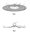
- a second exemplary embodiment of a safety device according to the invention is shown in figures 3 and 4, respectively in perspective view and in cross-section.
- This exemplary embodiment corresponds for the most part with that described above, except that in this embodiment one of the two flange-like bodies 22 is provided with protrusions, staples or nails 26 so as to exert more grip on the fastening flap 11 clamped between the two flange-like bodies 21,22.
- a comparable or additional extra grip can be obtained by similar protrusions, staples or nails in the other flange-like body or by roughening the surface of one or both flange-like bodies directed toward the fastening flap.
- protrusions 26 instead of or in addition to protrusions 26, one or more ridges can also be punched into one or both flange-like bodies.
- Figures 5, 6 and 7 show respectively a first and second perspective view and a cross-section of a third exemplary embodiment of a safety device according to the invention.
- the two flange-like bodies 21,22 are provided at corresponding positions with bores 27 for receiving therein nails 28 or other through-attaching members.
- Figure 5 here shows an upper side of the device while figure 6 shows an underside.
- Nails 28 are forced through fastening flap 11 from one of the two flange-like bodies and are received in the corresponding openings of the other flange-like body. The fixing of fastening flap 11 to the other part of the device can thus be realized as a permanent attachment.
- Use can optionally be made of shorter nails, screws or other attaching members which thereby penetrate only partially into the fastening flap so that the other flange-like body is not affected. Bores 27 or other recesses can in that case be omitted from this latter flange-like body. Instead of separate nails, nails can also be applied which are welded or otherwise fixedly connected to the relevant flange-like body.
- FIG 8 A top view of a fourth embodiment of a safety device according to the invention is shown in figure 8, wherein for the sake of clarity the fastening flap, which is otherwise present, is not further shown.
- the device comprises two flange-like bodies 21,22 which clamp a fastening flap therebetween with which the assembly can be attached fixedly to an outer wall, roof or other wall of an object.
- the lower flange-like body 21 has a significantly larger cross-section than the upper body so as to thereby provide a larger base for the assembly. The possible forces exerted on the device during a fall are thus distributed over a larger area.
- the lower flange-like body 21 is also provided in this embodiment with incisions 29 running at least substantially radially with respect to the centre thereof. These incisions allow a plastic deformation of body 21 and thus form as it were a crumple zone in the assembly. In the case of a fall the forces developing therein will result in a deformation of the body, which thereby absorbs a part of these forces. This reduces the load on the body of the falling person and thus prevents more serious injury.
- the upper flange-like body 22 shown here can optionally also be applied under the first flange-like body 21 so as to distribute the falling forces better over the first flange-like body 21.
- At least the lower flange-like body comprises in this embodiment two rings with perforations 31,32 around the cup 25 formed thereon.
- These perforations enhance in the first place the forming process of cup 25, which is manufactured by being pressed from a flat plate.
- the inner ring with perforations 31 provides this deformability.
- perforations 31,32 allow direct material contact between fastening flap 11 and a surface 10 at the position of flange-like body 21, which enhances the mutual attachment.
- Perforations 31,32 also impart a certain plastic deformability to the assembly during a possible fall, whereby as with the incisions 29 a certain shock absorption is achieved. This latter is particularly the case for the outer ring with perforations 32.
- FIG. 9 shows a fifth embodiment of a safety device according to the invention.
- a flexible fastening flap 11 is also clamped between two flange-like bodies 21,22, the lower 21 of which has larger dimensions.
- a screw bolt 2 having on an outer end a fixing eyelet 1 as anchoring member passes through the centre of an assembly and holds the assembly clampingly together due to the locking nut 3 screwed thereon.
- a peripheral edge 13 of the lower flange-like body 21 is bent so that the edge projects toward a side remote from fastening flap 11 and cannot therefore come into contact therewith.
- FIG. 10 A sixth embodiment of the safety device according to the invention is shown in figures 10 and 11, respectively in top view and in cross-section.
- this device comprises only one flange-like body 21 which is connected to a fastening flap 11 for instance by glueing or nailing.
- this flange-like body 21 provides a base for attaching an anchoring member in the form of a fixing eyelet 1 formed on a screw bolt, while fastening flap 11 is intended for glueing, welding or fusing to a surface for the purpose of a durable connection of the assembly to an object.
- an anchoring member which forms an integral part with the flange-like body or is permanently connected thereto by means of welding or in other manner.
- a seventh exemplary embodiment of the device is an example hereof and is shown in figure 12.
- an anchoring member in the form of a closed ring 1 is coupled to a set of crossed straps 15.
- straps 15 are in turn connected mechanically to a flexible fastening flap 11 with which the assembly can be attached to an object 10.
- the device according to the invention can also be applied in a system of safety devices so as to arrange a more extended anchoring cable.
- An eighth exemplary embodiment of a safety device according to the invention which can be applied in such a system is shown in figures 13-15.
- Use is made here of a set of two flange-like bodies as also applied in the above described exemplary embodiments of the invention, which may or may not be the same size and between which a fastening flap 11 is clamped.
- a central screw bolt with a fixing eyelet formed fixedly thereon use is made in this exemplary embodiment of a screw bolt with a normal head.
- this bolt also serves to fix a separate anchoring member 40 in the form of a cable bushing or cable guide for a safety cable 50, see also figures 14 and 15.
- the anchoring member 40 applied here comprises a flat base 41 with an upright 43 which extends therefrom and has a bent portion 44 close to the base.
- Base 41 comprises a central opening 42 into which fits the central bolt 2 with which anchoring member 40 is fastened to the other part of the device.
- Mounted on a free end of upright 43 is a hollow tube 45 through which safety cable 50 can be guided.
- Hollow tube 45 can take a straight form, see figure 14, but preferably narrows at either side, see figure 13, in order to effectively guide a so-called sliding carriage over safety cable 50 during use.
- the anchoring member is manufactured wholly from strong, impact-resistant material.
- stainless steel is applied for this purpose, wherein base 41 and upright 43 are formed from plate steel with a thickness in the order of 4-6 mm, while the hollow tube is welded thereon.
- Safety devices can be applied to guide a safety cable over a desired length in a desired path, see figure 15.
- the various safety devices are herein connected in the above described manner to a surface, or a bituminous roof-covering, by means of the flexible fastening flap.
- Safety cable 50 is generally received freely in the intermediate devices and attached fixedly to the outermost device.
- a person who goes onto a roof or to other high position where such safety devices are arranged can secure himself by means of a harness, lifeline and sliding carriage to anchoring member 50, and then has complete freedom of movement along the safety cable.
- the device according to the invention can in principle be applied on any structural type of roof or outer wall construction, wherein the strength of the construction is of secondary importance.
- Examples hereof are roof coverings or wall claddings of bitumen or plastic which are wholly or partially adhered, mechanically fixed or ballasted with loose material.
- the application of the safety device according to the invention complies with the EN 795 standard known to the skilled person. This standard describes the requirements for the testing methods for anchor provisions intended for personal protection against falls. The two essential points from the EN 795 standard are:
- the safety device for fall protection has in common that they are lightweight and can be mounted rapidly with simple means and tools.
- the force released during a fall is absorbed in elastic manner by the materials from which the device is manufactured.
- a plastic deformation of one or more components of the device will absorb a significant part of the kinetic energy of a fall. The forces are then transmitted to the existing covering of the roof or the outer wall or to the roof or the outer wall itself.
Landscapes
- Architecture (AREA)
- Engineering & Computer Science (AREA)
- Health & Medical Sciences (AREA)
- General Health & Medical Sciences (AREA)
- Business, Economics & Management (AREA)
- Emergency Management (AREA)
- Mechanical Engineering (AREA)
- Civil Engineering (AREA)
- Structural Engineering (AREA)
- Emergency Lowering Means (AREA)
- Helmets And Other Head Coverings (AREA)
- Fuses (AREA)
- Air Bags (AREA)
- Electrical Discharge Machining, Electrochemical Machining, And Combined Machining (AREA)
- Professional, Industrial, Or Sporting Protective Garments (AREA)
- Telephone Function (AREA)
- Building Environments (AREA)
- Support Of Aerials (AREA)
- Emergency Alarm Devices (AREA)
- Details Of Aerials (AREA)
- Clamps And Clips (AREA)
- Financial Or Insurance-Related Operations Such As Payment And Settlement (AREA)
- Roof Covering Using Slabs Or Stiff Sheets (AREA)
- Joining Of Building Structures In Genera (AREA)
Priority Applications (6)
| Application Number | Priority Date | Filing Date | Title |
|---|---|---|---|
| EP10183827.4A EP2287422A3 (fr) | 2003-12-24 | 2004-12-14 | Dispositif de sécurité pour dispositif antichute |
| EP19183721.0A EP3581736A1 (fr) | 2003-12-24 | 2004-12-14 | Dispositif de sécurité pour protection individuelle contre les chutes et objet doté du dispositif de sécurité |
| PL07105360T PL1803871T3 (pl) | 2003-12-24 | 2004-12-14 | Obiekt wyposażony w urządzenie zabezpieczające, przeznaczone do ochrony osób przed upadkiem |
| DK09178984T DK2163710T3 (da) | 2003-12-24 | 2004-12-14 | Fremgangsmåde til tilvejebringelse af en sikkerhedsanordning til personlig faldsikring |
| EP09178984.2A EP2163710B1 (fr) | 2003-12-24 | 2004-12-14 | Procédé d'installation d'un dispositif de sécurité contre les chutes |
| PL09178984T PL2163710T3 (pl) | 2003-12-24 | 2004-12-14 | Sposób zapewnienia urządzenia bezpieczeństwa do osobistej ochrony przed upadkiem |
Applications Claiming Priority (3)
| Application Number | Priority Date | Filing Date | Title |
|---|---|---|---|
| NL1025127A NL1025127C2 (nl) | 2003-12-24 | 2003-12-24 | Ankerpunt voor valbeveiliging. |
| NL1025821 | 2004-03-26 | ||
| EP04808785A EP1699991B1 (fr) | 2003-12-24 | 2004-12-14 | Dispositif de securite pour retenue anti-chute |
Related Parent Applications (2)
| Application Number | Title | Priority Date | Filing Date |
|---|---|---|---|
| EP04808785A Division EP1699991B1 (fr) | 2003-12-24 | 2004-12-14 | Dispositif de securite pour retenue anti-chute |
| EP04808785.2 Division | 2004-12-14 |
Related Child Applications (4)
| Application Number | Title | Priority Date | Filing Date |
|---|---|---|---|
| EP10183827.4A Division EP2287422A3 (fr) | 2003-12-24 | 2004-12-14 | Dispositif de sécurité pour dispositif antichute |
| EP19183721.0A Division EP3581736A1 (fr) | 2003-12-24 | 2004-12-14 | Dispositif de sécurité pour protection individuelle contre les chutes et objet doté du dispositif de sécurité |
| EP09178984.2A Division EP2163710B1 (fr) | 2003-12-24 | 2004-12-14 | Procédé d'installation d'un dispositif de sécurité contre les chutes |
| EP09178984.2 Division-Into | 2009-12-11 |
Publications (3)
| Publication Number | Publication Date |
|---|---|
| EP1803871A2 true EP1803871A2 (fr) | 2007-07-04 |
| EP1803871A3 EP1803871A3 (fr) | 2008-08-13 |
| EP1803871B1 EP1803871B1 (fr) | 2010-03-31 |
Family
ID=34713066
Family Applications (7)
| Application Number | Title | Priority Date | Filing Date |
|---|---|---|---|
| EP10183827.4A Pending EP2287422A3 (fr) | 2003-12-24 | 2004-12-14 | Dispositif de sécurité pour dispositif antichute |
| EP19183721.0A Pending EP3581736A1 (fr) | 2003-12-24 | 2004-12-14 | Dispositif de sécurité pour protection individuelle contre les chutes et objet doté du dispositif de sécurité |
| EP09178984.2A Expired - Lifetime EP2163710B1 (fr) | 2003-12-24 | 2004-12-14 | Procédé d'installation d'un dispositif de sécurité contre les chutes |
| EP04808785A Expired - Lifetime EP1699991B1 (fr) | 2003-12-24 | 2004-12-14 | Dispositif de securite pour retenue anti-chute |
| EP07105360A Expired - Lifetime EP1803871B1 (fr) | 2003-12-24 | 2004-12-14 | Objet pourvu d'un dispositif de sécurité pour protection personnelle contre la chute |
| EP04808810.8A Expired - Lifetime EP1699992B1 (fr) | 2003-12-24 | 2004-12-21 | Dispositif de securite pour systeme anti-chute |
| EP04808829.8A Expired - Lifetime EP1699993B1 (fr) | 2003-12-24 | 2004-12-24 | Dispositif de securite pour systeme anti-chute |
Family Applications Before (4)
| Application Number | Title | Priority Date | Filing Date |
|---|---|---|---|
| EP10183827.4A Pending EP2287422A3 (fr) | 2003-12-24 | 2004-12-14 | Dispositif de sécurité pour dispositif antichute |
| EP19183721.0A Pending EP3581736A1 (fr) | 2003-12-24 | 2004-12-14 | Dispositif de sécurité pour protection individuelle contre les chutes et objet doté du dispositif de sécurité |
| EP09178984.2A Expired - Lifetime EP2163710B1 (fr) | 2003-12-24 | 2004-12-14 | Procédé d'installation d'un dispositif de sécurité contre les chutes |
| EP04808785A Expired - Lifetime EP1699991B1 (fr) | 2003-12-24 | 2004-12-14 | Dispositif de securite pour retenue anti-chute |
Family Applications After (2)
| Application Number | Title | Priority Date | Filing Date |
|---|---|---|---|
| EP04808810.8A Expired - Lifetime EP1699992B1 (fr) | 2003-12-24 | 2004-12-21 | Dispositif de securite pour systeme anti-chute |
| EP04808829.8A Expired - Lifetime EP1699993B1 (fr) | 2003-12-24 | 2004-12-24 | Dispositif de securite pour systeme anti-chute |
Country Status (13)
| Country | Link |
|---|---|
| US (2) | US9643035B2 (fr) |
| EP (7) | EP2287422A3 (fr) |
| JP (1) | JP5416884B2 (fr) |
| CN (1) | CN100408795C (fr) |
| AT (2) | ATE381652T1 (fr) |
| CA (2) | CA2551556C (fr) |
| DE (2) | DE602004010846T2 (fr) |
| DK (3) | DK2163710T3 (fr) |
| NL (3) | NL1027728C2 (fr) |
| NO (2) | NO338669B1 (fr) |
| PL (3) | PL1699991T3 (fr) |
| RU (1) | RU2355853C2 (fr) |
| WO (3) | WO2005061817A1 (fr) |
Cited By (6)
| Publication number | Priority date | Publication date | Assignee | Title |
|---|---|---|---|---|
| NL1034126C2 (nl) * | 2007-07-13 | 2009-02-02 | Schuurman Tussenholding B V | Zekeringsinrichting voor een valbeveiliging. |
| NL1035225C2 (nl) * | 2008-03-31 | 2009-10-01 | Hutter Veiligheid B V | Valbeveiliging. |
| NL2001595C2 (nl) * | 2008-05-19 | 2009-11-20 | Kedge Holding Bv | Bevestigingsinrichting en valbeveiligingssysteem. |
| GB2464787A (en) * | 2009-07-18 | 2010-05-05 | Anne Marie Heister | Ladder anchor |
| FR2943920A1 (fr) * | 2009-04-03 | 2010-10-08 | Travel Mania | Organe de passage et de support d'une ligne de vie pour structure de jeu, et structure de jeu correspondante. |
| GB2473209A (en) * | 2009-09-02 | 2011-03-09 | Latchways Plc | Bracket fixing for a fall arrest safety line comprising a bolt held captive in a box structure. |
Families Citing this family (63)
| Publication number | Priority date | Publication date | Assignee | Title |
|---|---|---|---|---|
| WO2005094283A2 (fr) | 2004-03-25 | 2005-10-13 | Hauser David L | Dispositif de filtrage vasculaire |
| USD588717S1 (en) * | 2004-10-27 | 2009-03-17 | Deuer Joseph F | Fall prevention rope |
| DE202004017539U1 (de) * | 2004-11-11 | 2005-02-03 | Zinco Gmbh | System als Anschlagmöglichkeit für Schutzausrüstungen gegen Absturz |
| NL1031060C1 (nl) * | 2006-02-03 | 2007-08-06 | Veilig Dak Techniek B V | Zekeringsinrichting, afdekorgaan en werkwijze voor het voorkomen van vallen door personen van een verhoogd oppervlak. |
| US8025125B2 (en) * | 2006-11-03 | 2011-09-27 | D B Industries, Inc. | Anchor assembly |
| DE102006054408A1 (de) * | 2006-11-18 | 2008-06-05 | OBS Objekt-Begrünungs-Systeme GmbH | Absturzsicherung |
| NL1034006C1 (nl) * | 2007-06-20 | 2008-12-23 | Veilig Dak Techniek B V | Vertragingsinrichting en toepassing daarvan. |
| NL2000814C2 (nl) * | 2007-08-15 | 2009-02-23 | Safeway Gmbh | Veiligheidsvoorziening voor een dak. |
| BE1017967A4 (nl) | 2008-01-23 | 2010-02-02 | Aerialtech Sa | Verbetering meelopende valbeveiliging met flexibele ankerlijn. |
| DE102008008577A1 (de) * | 2008-02-11 | 2009-08-13 | Lufthansa Engineering And Operational Services Gmbh | Absturzsicherung |
| NL2004188C2 (nl) | 2009-02-04 | 2011-10-03 | Schuurman Beheer B V | Systeem voor valbeveiliging. |
| US8261878B2 (en) | 2010-01-13 | 2012-09-11 | Sunoco Partners Marketing & Terminals L.P. | Fall restraint system |
| WO2012055928A1 (fr) * | 2010-10-27 | 2012-05-03 | Icopal A/S | Dispositif de montage sur toit |
| WO2012177675A2 (fr) * | 2011-06-23 | 2012-12-27 | Honeywell International Inc. | Poteaux destinés à être utilisés dans une protection contre les chutes |
| NL2008121C2 (nl) * | 2012-01-13 | 2013-07-16 | Xsplatforms B V | Verankeringinrichting. |
| US9480865B2 (en) * | 2012-03-13 | 2016-11-01 | Bmc | Fall arrest system |
| US8784434B2 (en) | 2012-11-20 | 2014-07-22 | Inceptus Medical, Inc. | Methods and apparatus for treating embolism |
| US9821178B2 (en) | 2013-02-08 | 2017-11-21 | D B Industries, Llc | Bracket assembly |
| DE102013002971A1 (de) * | 2013-02-22 | 2014-08-28 | Péter Csizmadia | Fangschlitten mit Dämpfung und Dämpfungselemente für eine Absturzsicherung |
| US10238406B2 (en) | 2013-10-21 | 2019-03-26 | Inari Medical, Inc. | Methods and apparatus for treating embolism |
| CN104288935A (zh) * | 2014-09-12 | 2015-01-21 | 浙江百安固金属屋面有限公司 | 一种钢索防坠落系统及其安装方法 |
| US10060641B2 (en) * | 2015-02-25 | 2018-08-28 | Dri-Eaz Products, Inc. | Systems and methods for drying roofs |
| DK178631B1 (da) | 2015-09-08 | 2016-09-26 | Mul10 Metal As | Forankringssystem til montage på tage samt anvendelse af sådan et forankringssystem |
| CN108348319B (zh) | 2015-09-28 | 2020-03-10 | 斯瑞克公司 | 机械取栓装置和方法 |
| CA3241647A1 (fr) | 2015-10-23 | 2017-04-27 | Inari Medical, Inc. | Traitement intravasculaire d'occlusion vasculaire et dispositifs, systemes et procedes associes |
| US9878187B2 (en) * | 2015-12-04 | 2018-01-30 | Rooftop Anchor, Inc. | Joist anchor |
| JP6924256B2 (ja) | 2016-04-25 | 2021-08-25 | ストライカー コーポレイションStryker Corporation | 予め組み込まれた反転トラクタの血栓除去装置および方法 |
| US11896247B2 (en) | 2016-04-25 | 2024-02-13 | Stryker Corporation | Inverting mechanical thrombectomy apparatuses |
| US11497512B2 (en) | 2016-04-25 | 2022-11-15 | Stryker Corporation | Inverting thrombectomy apparatuses and methods |
| US10517624B2 (en) | 2016-06-03 | 2019-12-31 | Stryker Corporation | Inverting thrombectomy apparatuses and methods |
| JP2019526381A (ja) | 2016-09-12 | 2019-09-19 | ストライカー コーポレイションStryker Corporation | 自己転動血栓除去装置及び方法 |
| RU167382U1 (ru) * | 2016-09-22 | 2017-01-10 | Федеральное государственное бюджетное образовательное учреждение высшего образования "Томский государственный архитектурно-строительный университет" (ТГАСУ) | Конструкция для крепления средств защиты работающих на длинномерных высотных опорах |
| RU170531U1 (ru) * | 2016-11-17 | 2017-04-27 | федеральное государственное автономное образовательное учреждение высшего образования "Санкт-Петербургский политехнический университет Петра Великого" (ФГАОУ ВО "СПбПУ") | Стационарная анкерная точка на крыше |
| US9744387B1 (en) * | 2016-12-13 | 2017-08-29 | Yoke Industrial Corp. | Fixing device |
| DE102017100373A1 (de) * | 2017-01-10 | 2018-07-12 | Dws Pohl Gmbh | Vorrichtung zur Sicherung von Personen gegen Absturz |
| US10098651B2 (en) | 2017-01-10 | 2018-10-16 | Inari Medical, Inc. | Devices and methods for treating vascular occlusion |
| CA2974531A1 (fr) * | 2017-07-26 | 2019-01-26 | Michael Giroux | Ancrage de securite et event de toit |
| FI3678731T3 (fi) | 2017-09-06 | 2025-02-03 | Inari Medical Inc | Hemostaasiventtiilejä ja käyttömenetelmiä |
| CN107386674A (zh) * | 2017-09-14 | 2017-11-24 | 中亿丰建设集团股份有限公司 | 金属屋面双钢缆永久生命线系统 |
| EP4176830A1 (fr) | 2017-11-09 | 2023-05-10 | Stryker Corporation | Appareils de thrombectomie à inversion ayant un suivi amélioré |
| US11154314B2 (en) | 2018-01-26 | 2021-10-26 | Inari Medical, Inc. | Single insertion delivery system for treating embolism and associated systems and methods |
| CN112423683B (zh) | 2018-05-14 | 2024-06-18 | 史赛克公司 | 翻转血栓切除装置及使用方法 |
| US10737126B1 (en) * | 2018-07-31 | 2020-08-11 | Climb Tech, Llc | Wood anchoring device |
| DK3836855T3 (en) | 2018-08-13 | 2024-11-18 | Inari Medical Inc | System for treating embolism and associated devices and methods |
| ES2908031T3 (es) | 2018-09-10 | 2022-04-27 | Stryker Corp | Aparatos de trombectomía de inversión |
| EP3849440A1 (fr) | 2018-09-10 | 2021-07-21 | Stryker Corporation | Dispositif de préhension rainuré par laser |
| US11859870B2 (en) * | 2019-06-19 | 2024-01-02 | Patton Engineering, Inc. | Methods and systems for rigidly attaching components to roof structures |
| EP4044938A4 (fr) | 2019-10-16 | 2023-11-15 | Inari Medical, Inc. | Systèmes, dispositifs et procédés de traitement d'occlusions vasculaires |
| US11603675B2 (en) * | 2020-01-23 | 2023-03-14 | Steven Christopher Nichols | Devices, systems and methods relating to roof standing seam anchors |
| EP4093302B1 (fr) | 2020-01-23 | 2024-05-22 | Stryker Corporation | Appareils de capture d'inversion ayant des dépôts de matériau |
| NO345841B1 (en) * | 2020-03-26 | 2021-08-30 | Lonevag Beslagfabrikk As | Fixing Apparatus for a Roof |
| AU2021283979A1 (en) | 2020-06-05 | 2023-01-19 | Inari Medical, Inc. | Recapturable funnel catheters, and associated systems and methods |
| US20220228387A1 (en) * | 2021-01-21 | 2022-07-21 | Rooftop Anchor, Inc. | Triangular-shaped mounting device |
| GB2603497B (en) * | 2021-02-05 | 2025-01-01 | Latchways Plc | Anchor assembly |
| US11698166B1 (en) | 2021-08-11 | 2023-07-11 | Gregory F. Ryan | Emergency escape device and method of forming the emergency escape device |
| EP4158131B1 (fr) * | 2021-08-17 | 2025-07-02 | Sayfa R&D Pty Ltd | Ancrage de montage de toit antichute |
| AU2023208030A1 (en) | 2022-01-11 | 2024-07-18 | Inari Medical, Inc. | Devices for removing clot material from intravascularly implanted devices, and associated systems and methods |
| JP2026501789A (ja) | 2023-01-09 | 2026-01-16 | イナリ メディカル, インコーポレイテッド | 凝塊治療システムと共に使用するためのカテーテル |
| US20240342522A1 (en) * | 2023-04-14 | 2024-10-17 | Unified Safety Inc. | Anchor devices for fall protection |
| US20240376730A1 (en) * | 2023-05-08 | 2024-11-14 | Iron Fusion Enterprise, LLC | Swivel anchor |
| DK181614B1 (en) * | 2023-07-03 | 2024-06-28 | Spider Feet Aps | A support unit and a method for fastening a structure |
| US12558486B2 (en) | 2023-11-16 | 2026-02-24 | Inari Medical, Inc. | Automatic locking and unlocking vacuum syringes, and associated systems and methods |
| US12465382B1 (en) | 2024-05-10 | 2025-11-11 | Inari Medical, Inc. | Mechanical thrombectomy assemblies with relief features, and associated devices, systems, and methods |
Citations (2)
| Publication number | Priority date | Publication date | Assignee | Title |
|---|---|---|---|---|
| US5287944A (en) | 1993-02-03 | 1994-02-22 | Woodyard Clifford P | Roof mounted anchor used singly or with another, and with other equipment in a fall restraint and/or fall arrest system |
| US5687535A (en) | 1995-11-03 | 1997-11-18 | D B Industries, Inc. | Detachable roof anchor |
Family Cites Families (65)
| Publication number | Priority date | Publication date | Assignee | Title |
|---|---|---|---|---|
| US1883508A (en) * | 1930-02-06 | 1932-10-18 | Frederick W Bonday | Aerial support |
| US2079768A (en) * | 1935-06-27 | 1937-05-11 | Levow David | Snow guard |
| US2060953A (en) * | 1935-11-25 | 1936-11-17 | Arch Bulger J | Pole scaffold |
| US2280579A (en) * | 1941-03-25 | 1942-04-21 | Hardy James Harris | Roofing surface |
| US2404412A (en) * | 1943-10-07 | 1946-07-23 | Robert M Stephens | Vacuum cup |
| CH271254A (fr) * | 1948-02-17 | 1950-10-15 | Brun Justin | Equipement de sécurité. |
| US2703688A (en) * | 1954-06-23 | 1955-03-08 | William M Shuter | Service bracket |
| US2979153A (en) * | 1958-01-24 | 1961-04-11 | Standard Safety Equipment Co | Safety suit |
| US3157256A (en) * | 1961-08-25 | 1964-11-17 | Philco Corp | Ice anchor |
| US3307811A (en) * | 1965-07-27 | 1967-03-07 | Roy A Anderson | Wire tie down assembly |
| US3424134A (en) * | 1966-12-12 | 1969-01-28 | Irvin Industries Inc | Industrial safety harness |
| DE2343233A1 (de) * | 1973-08-28 | 1975-03-13 | Ertl Kg Baustoffwerk | Absturzsicherung |
| US4009763A (en) * | 1975-12-03 | 1977-03-01 | Hunter Alex E | Pole ladder |
| US4187590A (en) * | 1977-04-20 | 1980-02-12 | R. D. Bussard & Son, Inc. | Elastic fastener |
| US4120379A (en) * | 1977-08-22 | 1978-10-17 | Carter Samuel E | Tree stand and seat |
| US4244445A (en) * | 1979-04-18 | 1981-01-13 | Strode Clarence A | Support platform for vertical poles or trees |
| US4249713A (en) * | 1979-08-02 | 1981-02-10 | Glynn John H | Roof attachment member for safety lines |
| US4467581A (en) * | 1982-02-24 | 1984-08-28 | Single-Ply Institute Of America, Inc. | Membrane anchor system with metal body |
| SU1104223A1 (ru) * | 1983-04-08 | 1984-07-23 | Краснодарский филиал Всесоюзного научно-исследовательского института по монтажным и специальным строительным работам | Устройство дл страховки при работе на высоте |
| CA1187853A (fr) * | 1983-10-06 | 1985-05-28 | Kenneth Thaler | Ancrage et support pour appareils sur toiture |
| DE8531673U1 (de) * | 1985-11-09 | 1986-06-12 | Deitermann Chemiewerk Gmbh & Co Kg, 4354 Datteln | Halter für die lösbare Befestigung einer Anordnung von Wärmedämmplatten, insbesondere auf Dachflächen |
| US4744187A (en) * | 1987-01-27 | 1988-05-17 | The Firestone Tire & Rubber Company | Mechanical roof fastener |
| US4892429A (en) * | 1987-08-03 | 1990-01-09 | Giannuzzi Louis | Roof anchor and stress plate assembly |
| US4830341A (en) * | 1987-12-31 | 1989-05-16 | Institut De Recherche En Sante Et En Securite Du Travail Du Quebec | Anchor for temporary safety fence |
| CA1271464A (fr) * | 1988-03-25 | 1990-07-10 | Marc H. Lebel | Support d'ancrage pour lignes de surete d'un batiment |
| US5105910A (en) * | 1991-01-07 | 1992-04-21 | Engstrom Jay C | Portable tree stand assembly for hunters |
| US5168684A (en) * | 1991-05-28 | 1992-12-08 | Ronald Bruhm | Means for securing elastomeric sheathing to a roof surface |
| US5282597A (en) * | 1992-08-04 | 1994-02-01 | Michael A. Babcock | Safety line anchoring device |
| US5361558A (en) * | 1992-12-11 | 1994-11-08 | Stacy Thornton | Roof mountable safety line anchor |
| US5417636A (en) * | 1993-07-06 | 1995-05-23 | Havens; Suzanne | Body stretching and exercise mat system |
| US5433290A (en) * | 1993-10-04 | 1995-07-18 | Research & Trading Corporation | Safety line shock absorber |
| US5730407A (en) * | 1995-07-31 | 1998-03-24 | Ostrobrod; Meyer | Roof anchoring system with a safety line |
| US6098746A (en) * | 1995-08-10 | 2000-08-08 | Castaneda; Frank F. | Crown anchor for a roofing safety system |
| US5975239A (en) * | 1995-08-10 | 1999-11-02 | Castaneda; Frank F. | Anchor for a roofing safety system |
| US5730245A (en) * | 1996-04-02 | 1998-03-24 | Conway; John | Safety cable deck anchor |
| GB2313396B (en) * | 1996-04-18 | 2000-08-30 | Acimex | Fall arrest device |
| US5738046A (en) * | 1996-07-22 | 1998-04-14 | Williams; Tommie Ann | Safety jacket and harness system |
| US5829203A (en) * | 1996-12-24 | 1998-11-03 | Ealer, Sr.; James Edward | Roof safety bracket |
| US5848666A (en) * | 1997-03-05 | 1998-12-15 | Woodall; Wilbur J. | Adjustable tree stand |
| JPH1136605A (ja) * | 1997-07-18 | 1999-02-09 | Asahi Chem Ind Co Ltd | 安全ロープ取付具及び安全ロープ取付用固定構造 |
| CA2241832A1 (fr) * | 1998-06-29 | 1999-12-29 | Industrial Thermo Polymers Limited | Organe d'assemblage avec bobine plane |
| DE19959591A1 (de) * | 1998-12-16 | 2000-06-21 | Henkel Kgaa | Verbundblechflansche für Absturzsicherungen |
| EP1036575B1 (fr) * | 1999-03-16 | 2004-05-12 | Protecta International | Méthode et dispositif d'ancrage d'une corde de sécurité |
| US6128782A (en) * | 1999-04-21 | 2000-10-10 | Young; David A. | Combination clothing/safety harness for fall arresting and rescue from confined spaces |
| US6526701B2 (en) * | 2000-07-03 | 2003-03-04 | Vermont Slate & Copper Services, Inc. | Roof mount |
| US6318941B1 (en) * | 2000-07-20 | 2001-11-20 | Torbett B. Guenther | Wall anchor |
| US6508446B1 (en) * | 2000-07-27 | 2003-01-21 | Julie H. Addison | Portable swing system |
| JP4376432B2 (ja) * | 2000-07-27 | 2009-12-02 | 積水化学工業株式会社 | 親綱固定金具および屋根構造 |
| AUPQ942200A0 (en) * | 2000-08-15 | 2000-09-07 | Poldmaa, Arvo | Roof anchor method and apparatus |
| GB0029047D0 (en) * | 2000-11-29 | 2001-01-10 | Uniline Safety Systems Ltd | Supporting bracket assembly for a horizontal lifeline cable |
| US6779316B2 (en) * | 2001-01-31 | 2004-08-24 | Kenneth Carroll | Safety anchor |
| US6892395B2 (en) * | 2001-02-14 | 2005-05-17 | James R. Schweer | Safety garment having safety harness |
| DE20109056U1 (de) | 2001-05-22 | 2001-10-11 | Zink, Rainer, 72622 Nürtingen | Gewebe durch Auflast aus Schüttgut gehalten, zur individuellen Schaffung von Anschlagmöglichkeiten für Schutzausrüstungen gegen Absturz |
| DE10333113B3 (de) * | 2003-07-21 | 2004-11-18 | Optigrün international AG | Absturzsicherung für Dächer mit Dachauflast |
| US7008158B2 (en) * | 2004-02-05 | 2006-03-07 | Madden Iii James William | Bolt or nut locking fastener and fastening system |
| CA2489107A1 (fr) * | 2004-07-23 | 2006-01-23 | Thaler Metal Industries Ltd. | Dispositif amortisseur pour systeme de filin de secours horizontal |
| US7914057B2 (en) * | 2005-06-02 | 2011-03-29 | D B Industries, Inc. | Vacuum anchor |
| US20070007503A1 (en) * | 2005-07-07 | 2007-01-11 | Rafael Martinez | Truss mounted rooftop fall protection system |
| US8181743B2 (en) * | 2007-03-29 | 2012-05-22 | Ducellier Jason | Portable tree stand |
| US8434274B2 (en) * | 2011-01-06 | 2013-05-07 | Clifford M. Anderson, JR. | Raptor nest exclusion device |
| US8733718B2 (en) * | 2012-05-10 | 2014-05-27 | Peter A. CORSI | Non-invasive roof mounting adaptor and method for installing same |
| US9550092B2 (en) * | 2012-07-23 | 2017-01-24 | Hurricane Safety Systems, Llc | Hand grip assembly |
| US9027709B2 (en) * | 2013-01-09 | 2015-05-12 | Advanced Treestand Investments, LLC | Modular tree stand |
| US20140224579A1 (en) * | 2013-02-13 | 2014-08-14 | Allan Joseph Balascak | Fall protection system |
| US20160128317A1 (en) * | 2014-11-07 | 2016-05-12 | Theodore Robert Gerry | Assistive apparatus for hanging a tree stand |
-
2004
- 2004-12-13 NL NL1027728A patent/NL1027728C2/nl not_active IP Right Cessation
- 2004-12-14 AT AT04808785T patent/ATE381652T1/de active
- 2004-12-14 WO PCT/NL2004/000869 patent/WO2005061817A1/fr not_active Ceased
- 2004-12-14 PL PL04808785T patent/PL1699991T3/pl unknown
- 2004-12-14 CA CA2551556A patent/CA2551556C/fr not_active Expired - Lifetime
- 2004-12-14 AT AT07105360T patent/ATE462849T1/de active
- 2004-12-14 RU RU2006126658/03A patent/RU2355853C2/ru active
- 2004-12-14 DE DE602004010846T patent/DE602004010846T2/de not_active Expired - Lifetime
- 2004-12-14 EP EP10183827.4A patent/EP2287422A3/fr active Pending
- 2004-12-14 EP EP19183721.0A patent/EP3581736A1/fr active Pending
- 2004-12-14 DE DE602004026369T patent/DE602004026369D1/de not_active Expired - Lifetime
- 2004-12-14 EP EP09178984.2A patent/EP2163710B1/fr not_active Expired - Lifetime
- 2004-12-14 US US10/584,215 patent/US9643035B2/en active Active
- 2004-12-14 CN CNB2004800390882A patent/CN100408795C/zh not_active Expired - Lifetime
- 2004-12-14 DK DK09178984T patent/DK2163710T3/da active
- 2004-12-14 PL PL07105360T patent/PL1803871T3/pl unknown
- 2004-12-14 EP EP04808785A patent/EP1699991B1/fr not_active Expired - Lifetime
- 2004-12-14 JP JP2006546866A patent/JP5416884B2/ja not_active Expired - Fee Related
- 2004-12-14 EP EP07105360A patent/EP1803871B1/fr not_active Expired - Lifetime
- 2004-12-14 DK DK07105360.7T patent/DK1803871T3/da active
- 2004-12-14 DK DK04808785T patent/DK1699991T3/da active
- 2004-12-14 PL PL09178984T patent/PL2163710T3/pl unknown
- 2004-12-21 NL NL1027834A patent/NL1027834C2/nl not_active IP Right Cessation
- 2004-12-21 WO PCT/NL2004/000894 patent/WO2005061818A1/fr not_active Ceased
- 2004-12-21 CA CA2550970A patent/CA2550970C/fr not_active Expired - Lifetime
- 2004-12-21 EP EP04808810.8A patent/EP1699992B1/fr not_active Expired - Lifetime
- 2004-12-21 US US10/584,216 patent/US20070163835A1/en not_active Abandoned
- 2004-12-24 WO PCT/NL2004/000913 patent/WO2005061819A1/fr not_active Ceased
- 2004-12-24 NL NL1027888A patent/NL1027888C2/nl not_active IP Right Cessation
- 2004-12-24 EP EP04808829.8A patent/EP1699993B1/fr not_active Expired - Lifetime
-
2006
- 2006-07-21 NO NO20063398A patent/NO338669B1/no unknown
- 2006-07-24 NO NO20063406A patent/NO336860B1/no unknown
Patent Citations (2)
| Publication number | Priority date | Publication date | Assignee | Title |
|---|---|---|---|---|
| US5287944A (en) | 1993-02-03 | 1994-02-22 | Woodyard Clifford P | Roof mounted anchor used singly or with another, and with other equipment in a fall restraint and/or fall arrest system |
| US5687535A (en) | 1995-11-03 | 1997-11-18 | D B Industries, Inc. | Detachable roof anchor |
Cited By (11)
| Publication number | Priority date | Publication date | Assignee | Title |
|---|---|---|---|---|
| NL1034126C2 (nl) * | 2007-07-13 | 2009-02-02 | Schuurman Tussenholding B V | Zekeringsinrichting voor een valbeveiliging. |
| NL1035225C2 (nl) * | 2008-03-31 | 2009-10-01 | Hutter Veiligheid B V | Valbeveiliging. |
| NL2001595C2 (nl) * | 2008-05-19 | 2009-11-20 | Kedge Holding Bv | Bevestigingsinrichting en valbeveiligingssysteem. |
| WO2009142480A1 (fr) * | 2008-05-19 | 2009-11-26 | Kedge Holding B.V. | Dispositif de montage et système de protection contre la chute |
| RU2494778C2 (ru) * | 2008-05-19 | 2013-10-10 | Кедж Холдинг Б.В. | Крепежное устройство и система защиты от падения |
| US9566458B2 (en) | 2008-05-19 | 2017-02-14 | Kedge Holding B.V. | Mounting device and fall protection system |
| FR2943920A1 (fr) * | 2009-04-03 | 2010-10-08 | Travel Mania | Organe de passage et de support d'une ligne de vie pour structure de jeu, et structure de jeu correspondante. |
| GB2464787A (en) * | 2009-07-18 | 2010-05-05 | Anne Marie Heister | Ladder anchor |
| GB2464787B (en) * | 2009-07-18 | 2011-02-09 | Anne Marie Heister | A wall with a ladder anchor |
| GB2473209A (en) * | 2009-09-02 | 2011-03-09 | Latchways Plc | Bracket fixing for a fall arrest safety line comprising a bolt held captive in a box structure. |
| GB2473209B (en) * | 2009-09-02 | 2014-12-03 | Latchways Plc | Bracket fixing for a safety line |
Also Published As
Similar Documents
| Publication | Publication Date | Title |
|---|---|---|
| EP1699991B1 (fr) | Dispositif de securite pour retenue anti-chute | |
| AU744587B1 (en) | Improvements in roof anchors | |
| CA2666210C (fr) | Dispositif d'ancrage de toit | |
| US5727646A (en) | Retractable fall restraint device | |
| KR20080006223U (ko) | 건축용 비계클램프 결합구조 | |
| DK178036B1 (da) | Faldsikring | |
| AU2009210368B2 (en) | Roof anchor cable system having shock absorbing means | |
| AU2013100441A4 (en) | Roof Anchor Cable System Having Shock Absorbing Means | |
| CA2605063A1 (fr) | Dispositif de securite pour le secteur de la construction | |
| NZ553425A (en) | A safety anchor |
Legal Events
| Date | Code | Title | Description |
|---|---|---|---|
| PUAI | Public reference made under article 153(3) epc to a published international application that has entered the european phase |
Free format text: ORIGINAL CODE: 0009012 |
|
| AC | Divisional application: reference to earlier application |
Ref document number: 1699991 Country of ref document: EP Kind code of ref document: P |
|
| AK | Designated contracting states |
Kind code of ref document: A2 Designated state(s): AT BE BG CH CY CZ DE DK EE ES FI FR GB GR HU IE IS IT LI LT LU MC NL PL PT RO SE SI SK TR |
|
| PUAL | Search report despatched |
Free format text: ORIGINAL CODE: 0009013 |
|
| AK | Designated contracting states |
Kind code of ref document: A3 Designated state(s): AT BE BG CH CY CZ DE DK EE ES FI FR GB GR HU IE IS IT LI LT LU MC NL PL PT RO SE SI SK TR |
|
| 17P | Request for examination filed |
Effective date: 20071127 |
|
| AKX | Designation fees paid |
Designated state(s): AT BE BG CH CY CZ DE DK EE ES FI FR GB GR HU IE IS IT LI LT LU MC NL PL PT RO SE SI SK TR |
|
| 17Q | First examination report despatched |
Effective date: 20090403 |
|
| GRAP | Despatch of communication of intention to grant a patent |
Free format text: ORIGINAL CODE: EPIDOSNIGR1 |
|
| RTI1 | Title (correction) |
Free format text: OBJECT PROVIDED WITH A SAFETY DEVICE FOR A PERSONAL FALL PROTECTION |
|
| GRAS | Grant fee paid |
Free format text: ORIGINAL CODE: EPIDOSNIGR3 |
|
| GRAA | (expected) grant |
Free format text: ORIGINAL CODE: 0009210 |
|
| AC | Divisional application: reference to earlier application |
Ref document number: 1699991 Country of ref document: EP Kind code of ref document: P |
|
| AK | Designated contracting states |
Kind code of ref document: B1 Designated state(s): AT BE BG CH CY CZ DE DK EE ES FI FR GB GR HU IE IS IT LI LT LU MC NL PL PT RO SE SI SK TR |
|
| REG | Reference to a national code |
Ref country code: GB Ref legal event code: FG4D Ref country code: CH Ref legal event code: EP |
|
| REG | Reference to a national code |
Ref country code: NL Ref legal event code: T3 |
|
| REG | Reference to a national code |
Ref country code: IE Ref legal event code: FG4D |
|
| REF | Corresponds to: |
Ref document number: 602004026369 Country of ref document: DE Date of ref document: 20100512 Kind code of ref document: P |
|
| REG | Reference to a national code |
Ref country code: DK Ref legal event code: T3 |
|
| REG | Reference to a national code |
Ref country code: SE Ref legal event code: TRGR |
|
| PG25 | Lapsed in a contracting state [announced via postgrant information from national office to epo] |
Ref country code: LT Free format text: LAPSE BECAUSE OF FAILURE TO SUBMIT A TRANSLATION OF THE DESCRIPTION OR TO PAY THE FEE WITHIN THE PRESCRIBED TIME-LIMIT Effective date: 20100331 |
|
| LTIE | Lt: invalidation of european patent or patent extension |
Effective date: 20100331 |
|
| PG25 | Lapsed in a contracting state [announced via postgrant information from national office to epo] |
Ref country code: SI Free format text: LAPSE BECAUSE OF FAILURE TO SUBMIT A TRANSLATION OF THE DESCRIPTION OR TO PAY THE FEE WITHIN THE PRESCRIBED TIME-LIMIT Effective date: 20100331 Ref country code: FI Free format text: LAPSE BECAUSE OF FAILURE TO SUBMIT A TRANSLATION OF THE DESCRIPTION OR TO PAY THE FEE WITHIN THE PRESCRIBED TIME-LIMIT Effective date: 20100331 |
|
| REG | Reference to a national code |
Ref country code: CH Ref legal event code: NV Representative=s name: ABREMA AGENCE BREVET ET MARQUES, GANGUILLET |
|
| PG25 | Lapsed in a contracting state [announced via postgrant information from national office to epo] |
Ref country code: ES Free format text: LAPSE BECAUSE OF FAILURE TO SUBMIT A TRANSLATION OF THE DESCRIPTION OR TO PAY THE FEE WITHIN THE PRESCRIBED TIME-LIMIT Effective date: 20100712 Ref country code: RO Free format text: LAPSE BECAUSE OF FAILURE TO SUBMIT A TRANSLATION OF THE DESCRIPTION OR TO PAY THE FEE WITHIN THE PRESCRIBED TIME-LIMIT Effective date: 20100331 Ref country code: EE Free format text: LAPSE BECAUSE OF FAILURE TO SUBMIT A TRANSLATION OF THE DESCRIPTION OR TO PAY THE FEE WITHIN THE PRESCRIBED TIME-LIMIT Effective date: 20100331 Ref country code: CY Free format text: LAPSE BECAUSE OF FAILURE TO SUBMIT A TRANSLATION OF THE DESCRIPTION OR TO PAY THE FEE WITHIN THE PRESCRIBED TIME-LIMIT Effective date: 20100331 |
|
| REG | Reference to a national code |
Ref country code: PL Ref legal event code: T3 |
|
| PG25 | Lapsed in a contracting state [announced via postgrant information from national office to epo] |
Ref country code: IS Free format text: LAPSE BECAUSE OF FAILURE TO SUBMIT A TRANSLATION OF THE DESCRIPTION OR TO PAY THE FEE WITHIN THE PRESCRIBED TIME-LIMIT Effective date: 20100731 Ref country code: SK Free format text: LAPSE BECAUSE OF FAILURE TO SUBMIT A TRANSLATION OF THE DESCRIPTION OR TO PAY THE FEE WITHIN THE PRESCRIBED TIME-LIMIT Effective date: 20100331 |
|
| PLBI | Opposition filed |
Free format text: ORIGINAL CODE: 0009260 |
|
| PG25 | Lapsed in a contracting state [announced via postgrant information from national office to epo] |
Ref country code: PT Free format text: LAPSE BECAUSE OF FAILURE TO SUBMIT A TRANSLATION OF THE DESCRIPTION OR TO PAY THE FEE WITHIN THE PRESCRIBED TIME-LIMIT Effective date: 20100802 |
|
| 26 | Opposition filed |
Opponent name: SAFEWAY GMBH Effective date: 20101223 |
|
| PLAX | Notice of opposition and request to file observation + time limit sent |
Free format text: ORIGINAL CODE: EPIDOSNOBS2 |
|
| PG25 | Lapsed in a contracting state [announced via postgrant information from national office to epo] |
Ref country code: IT Free format text: LAPSE BECAUSE OF FAILURE TO SUBMIT A TRANSLATION OF THE DESCRIPTION OR TO PAY THE FEE WITHIN THE PRESCRIBED TIME-LIMIT Effective date: 20100331 |
|
| PLAF | Information modified related to communication of a notice of opposition and request to file observations + time limit |
Free format text: ORIGINAL CODE: EPIDOSCOBS2 |
|
| PG25 | Lapsed in a contracting state [announced via postgrant information from national office to epo] |
Ref country code: MC Free format text: LAPSE BECAUSE OF NON-PAYMENT OF DUE FEES Effective date: 20101231 |
|
| PLBB | Reply of patent proprietor to notice(s) of opposition received |
Free format text: ORIGINAL CODE: EPIDOSNOBS3 |
|
| PLBP | Opposition withdrawn |
Free format text: ORIGINAL CODE: 0009264 |
|
| PLBD | Termination of opposition procedure: decision despatched |
Free format text: ORIGINAL CODE: EPIDOSNOPC1 |
|
| PG25 | Lapsed in a contracting state [announced via postgrant information from national office to epo] |
Ref country code: HU Free format text: LAPSE BECAUSE OF FAILURE TO SUBMIT A TRANSLATION OF THE DESCRIPTION OR TO PAY THE FEE WITHIN THE PRESCRIBED TIME-LIMIT Effective date: 20101001 Ref country code: BG Free format text: LAPSE BECAUSE OF FAILURE TO SUBMIT A TRANSLATION OF THE DESCRIPTION OR TO PAY THE FEE WITHIN THE PRESCRIBED TIME-LIMIT Effective date: 20100331 Ref country code: LU Free format text: LAPSE BECAUSE OF NON-PAYMENT OF DUE FEES Effective date: 20101214 |
|
| PLBM | Termination of opposition procedure: date of legal effect published |
Free format text: ORIGINAL CODE: 0009276 |
|
| STAA | Information on the status of an ep patent application or granted ep patent |
Free format text: STATUS: OPPOSITION PROCEDURE CLOSED |
|
| 27C | Opposition proceedings terminated |
Effective date: 20120622 |
|
| PG25 | Lapsed in a contracting state [announced via postgrant information from national office to epo] |
Ref country code: TR Free format text: LAPSE BECAUSE OF FAILURE TO SUBMIT A TRANSLATION OF THE DESCRIPTION OR TO PAY THE FEE WITHIN THE PRESCRIBED TIME-LIMIT Effective date: 20100331 |
|
| PG25 | Lapsed in a contracting state [announced via postgrant information from national office to epo] |
Ref country code: BG Free format text: LAPSE BECAUSE OF FAILURE TO SUBMIT A TRANSLATION OF THE DESCRIPTION OR TO PAY THE FEE WITHIN THE PRESCRIBED TIME-LIMIT Effective date: 20100630 |
|
| PG25 | Lapsed in a contracting state [announced via postgrant information from national office to epo] |
Ref country code: GR Free format text: LAPSE BECAUSE OF FAILURE TO SUBMIT A TRANSLATION OF THE DESCRIPTION OR TO PAY THE FEE WITHIN THE PRESCRIBED TIME-LIMIT Effective date: 20100331 |
|
| REG | Reference to a national code |
Ref country code: FR Ref legal event code: PLFP Year of fee payment: 12 |
|
| REG | Reference to a national code |
Ref country code: FR Ref legal event code: PLFP Year of fee payment: 13 |
|
| REG | Reference to a national code |
Ref country code: FR Ref legal event code: PLFP Year of fee payment: 14 |
|
| REG | Reference to a national code |
Ref country code: CH Ref legal event code: PFUS Owner name: KEDGE HOLDING B.V., NL Free format text: FORMER OWNER: KEDGE HOLDING B.V., NL |
|
| P01 | Opt-out of the competence of the unified patent court (upc) registered |
Effective date: 20230526 |
|
| PGFP | Annual fee paid to national office [announced via postgrant information from national office to epo] |
Ref country code: GB Payment date: 20231214 Year of fee payment: 20 |
|
| PGFP | Annual fee paid to national office [announced via postgrant information from national office to epo] |
Ref country code: NL Payment date: 20231220 Year of fee payment: 20 Ref country code: IE Payment date: 20231220 Year of fee payment: 20 Ref country code: FR Payment date: 20231221 Year of fee payment: 20 Ref country code: DK Payment date: 20231227 Year of fee payment: 20 Ref country code: DE Payment date: 20231214 Year of fee payment: 20 Ref country code: CZ Payment date: 20231206 Year of fee payment: 20 Ref country code: AT Payment date: 20231221 Year of fee payment: 20 Ref country code: SE Payment date: 20231220 Year of fee payment: 20 |
|
| PGFP | Annual fee paid to national office [announced via postgrant information from national office to epo] |
Ref country code: PL Payment date: 20231130 Year of fee payment: 20 Ref country code: BE Payment date: 20231220 Year of fee payment: 20 |
|
| PGFP | Annual fee paid to national office [announced via postgrant information from national office to epo] |
Ref country code: CH Payment date: 20240101 Year of fee payment: 20 |
|
| REG | Reference to a national code |
Ref country code: DE Ref legal event code: R071 Ref document number: 602004026369 Country of ref document: DE |
|
| REG | Reference to a national code |
Ref country code: DK Ref legal event code: EUP Expiry date: 20241214 |
|
| REG | Reference to a national code |
Ref country code: NL Ref legal event code: MK Effective date: 20241213 |
|
| REG | Reference to a national code |
Ref country code: BE Ref legal event code: MK Effective date: 20241214 |
|
| REG | Reference to a national code |
Ref country code: CH Ref legal event code: PL |
|
| REG | Reference to a national code |
Ref country code: GB Ref legal event code: PE20 Expiry date: 20241213 |
|
| PG25 | Lapsed in a contracting state [announced via postgrant information from national office to epo] |
Ref country code: GB Free format text: LAPSE BECAUSE OF EXPIRATION OF PROTECTION Effective date: 20241213 |
|
| PG25 | Lapsed in a contracting state [announced via postgrant information from national office to epo] |
Ref country code: CZ Free format text: LAPSE BECAUSE OF EXPIRATION OF PROTECTION Effective date: 20241214 Ref country code: IE Free format text: LAPSE BECAUSE OF EXPIRATION OF PROTECTION Effective date: 20241214 |
|
| REG | Reference to a national code |
Ref country code: SE Ref legal event code: EUG |
|
| REG | Reference to a national code |
Ref country code: IE Ref legal event code: MK9A |
|
| PG25 | Lapsed in a contracting state [announced via postgrant information from national office to epo] |
Ref country code: IE Free format text: LAPSE BECAUSE OF EXPIRATION OF PROTECTION Effective date: 20241214 Ref country code: GB Free format text: LAPSE BECAUSE OF EXPIRATION OF PROTECTION Effective date: 20241213 Ref country code: CZ Free format text: LAPSE BECAUSE OF EXPIRATION OF PROTECTION Effective date: 20241214 |
|
| REG | Reference to a national code |
Ref country code: AT Ref legal event code: MK07 Ref document number: 462849 Country of ref document: AT Kind code of ref document: T Effective date: 20241214 |