EP1804306A1 - Installation pour la production en continu d'une bande supraconductrice et procédé de traitement de surface correspondant - Google Patents
Installation pour la production en continu d'une bande supraconductrice et procédé de traitement de surface correspondant Download PDFInfo
- Publication number
- EP1804306A1 EP1804306A1 EP05113039A EP05113039A EP1804306A1 EP 1804306 A1 EP1804306 A1 EP 1804306A1 EP 05113039 A EP05113039 A EP 05113039A EP 05113039 A EP05113039 A EP 05113039A EP 1804306 A1 EP1804306 A1 EP 1804306A1
- Authority
- EP
- European Patent Office
- Prior art keywords
- treatment chamber
- connection unit
- tape
- treatment
- chambers
- Prior art date
- Legal status (The legal status is an assumption and is not a legal conclusion. Google has not performed a legal analysis and makes no representation as to the accuracy of the status listed.)
- Granted
Links
- 238000004519 manufacturing process Methods 0.000 title claims abstract description 21
- 238000000034 method Methods 0.000 title claims abstract description 20
- 230000008569 process Effects 0.000 title claims abstract description 19
- 238000004381 surface treatment Methods 0.000 title claims description 13
- 238000002203 pretreatment Methods 0.000 claims abstract description 17
- 238000005086 pumping Methods 0.000 claims abstract description 15
- 230000000694 effects Effects 0.000 claims abstract description 4
- 238000004804 winding Methods 0.000 claims abstract description 3
- 239000000758 substrate Substances 0.000 claims description 16
- 239000007789 gas Substances 0.000 claims description 13
- XKRFYHLGVUSROY-UHFFFAOYSA-N Argon Chemical compound [Ar] XKRFYHLGVUSROY-UHFFFAOYSA-N 0.000 claims description 8
- 238000000151 deposition Methods 0.000 claims description 8
- 230000008021 deposition Effects 0.000 claims description 7
- 239000000203 mixture Substances 0.000 claims description 6
- UFHFLCQGNIYNRP-UHFFFAOYSA-N Hydrogen Chemical compound [H][H] UFHFLCQGNIYNRP-UHFFFAOYSA-N 0.000 claims description 4
- 229910052786 argon Inorganic materials 0.000 claims description 4
- QVGXLLKOCUKJST-UHFFFAOYSA-N atomic oxygen Chemical compound [O] QVGXLLKOCUKJST-UHFFFAOYSA-N 0.000 claims description 4
- 230000000295 complement effect Effects 0.000 claims description 4
- 239000001257 hydrogen Substances 0.000 claims description 4
- 229910052739 hydrogen Inorganic materials 0.000 claims description 4
- 239000001301 oxygen Substances 0.000 claims description 4
- 229910052760 oxygen Inorganic materials 0.000 claims description 4
- 238000007789 sealing Methods 0.000 claims description 4
- 239000011248 coating agent Substances 0.000 claims description 3
- 238000000576 coating method Methods 0.000 claims description 3
- 230000001590 oxidative effect Effects 0.000 claims description 3
- 238000002207 thermal evaporation Methods 0.000 claims description 3
- 229910052782 aluminium Inorganic materials 0.000 claims description 2
- XAGFODPZIPBFFR-UHFFFAOYSA-N aluminium Chemical compound [Al] XAGFODPZIPBFFR-UHFFFAOYSA-N 0.000 claims description 2
- 238000010438 heat treatment Methods 0.000 claims description 2
- 229910001220 stainless steel Inorganic materials 0.000 claims description 2
- 239000010935 stainless steel Substances 0.000 claims description 2
- 238000000926 separation method Methods 0.000 claims 1
- 239000004020 conductor Substances 0.000 description 3
- 238000005516 engineering process Methods 0.000 description 3
- 239000002887 superconductor Substances 0.000 description 3
- 238000001771 vacuum deposition Methods 0.000 description 3
- 230000008901 benefit Effects 0.000 description 2
- 239000000919 ceramic Substances 0.000 description 2
- 229910000420 cerium oxide Inorganic materials 0.000 description 2
- 239000010949 copper Substances 0.000 description 2
- 230000002596 correlated effect Effects 0.000 description 2
- 238000005137 deposition process Methods 0.000 description 2
- 239000000463 material Substances 0.000 description 2
- BMMGVYCKOGBVEV-UHFFFAOYSA-N oxo(oxoceriooxy)cerium Chemical compound [Ce]=O.O=[Ce]=O BMMGVYCKOGBVEV-UHFFFAOYSA-N 0.000 description 2
- RYGMFSIKBFXOCR-UHFFFAOYSA-N Copper Chemical compound [Cu] RYGMFSIKBFXOCR-UHFFFAOYSA-N 0.000 description 1
- 230000004913 activation Effects 0.000 description 1
- 230000004888 barrier function Effects 0.000 description 1
- 238000010924 continuous production Methods 0.000 description 1
- 229910052802 copper Inorganic materials 0.000 description 1
- 230000008878 coupling Effects 0.000 description 1
- 238000010168 coupling process Methods 0.000 description 1
- 238000005859 coupling reaction Methods 0.000 description 1
- 230000001419 dependent effect Effects 0.000 description 1
- 230000006866 deterioration Effects 0.000 description 1
- 230000008020 evaporation Effects 0.000 description 1
- 238000001704 evaporation Methods 0.000 description 1
- 229910052736 halogen Inorganic materials 0.000 description 1
- 150000002367 halogens Chemical class 0.000 description 1
- 238000011065 in-situ storage Methods 0.000 description 1
- 229910052751 metal Inorganic materials 0.000 description 1
- 239000002184 metal Substances 0.000 description 1
- 238000002156 mixing Methods 0.000 description 1
- 230000004048 modification Effects 0.000 description 1
- 238000012986 modification Methods 0.000 description 1
- 229910052761 rare earth metal Inorganic materials 0.000 description 1
- 150000002910 rare earth metals Chemical class 0.000 description 1
- 230000009467 reduction Effects 0.000 description 1
- 230000000284 resting effect Effects 0.000 description 1
- 239000000126 substance Substances 0.000 description 1
- 230000001360 synchronised effect Effects 0.000 description 1
- 238000007669 thermal treatment Methods 0.000 description 1
Images


Classifications
-
- C—CHEMISTRY; METALLURGY
- C23—COATING METALLIC MATERIAL; COATING MATERIAL WITH METALLIC MATERIAL; CHEMICAL SURFACE TREATMENT; DIFFUSION TREATMENT OF METALLIC MATERIAL; COATING BY VACUUM EVAPORATION, BY SPUTTERING, BY ION IMPLANTATION OR BY CHEMICAL VAPOUR DEPOSITION, IN GENERAL; INHIBITING CORROSION OF METALLIC MATERIAL OR INCRUSTATION IN GENERAL
- C23C—COATING METALLIC MATERIAL; COATING MATERIAL WITH METALLIC MATERIAL; SURFACE TREATMENT OF METALLIC MATERIAL BY DIFFUSION INTO THE SURFACE, BY CHEMICAL CONVERSION OR SUBSTITUTION; COATING BY VACUUM EVAPORATION, BY SPUTTERING, BY ION IMPLANTATION OR BY CHEMICAL VAPOUR DEPOSITION, IN GENERAL
- C23C14/00—Coating by vacuum evaporation, by sputtering or by ion implantation of the coating forming material
- C23C14/22—Coating by vacuum evaporation, by sputtering or by ion implantation of the coating forming material characterised by the process of coating
- C23C14/56—Apparatus specially adapted for continuous coating; Arrangements for maintaining the vacuum, e.g. vacuum locks
- C23C14/562—Apparatus specially adapted for continuous coating; Arrangements for maintaining the vacuum, e.g. vacuum locks for coating elongated substrates
-
- F—MECHANICAL ENGINEERING; LIGHTING; HEATING; WEAPONS; BLASTING
- F16—ENGINEERING ELEMENTS AND UNITS; GENERAL MEASURES FOR PRODUCING AND MAINTAINING EFFECTIVE FUNCTIONING OF MACHINES OR INSTALLATIONS; THERMAL INSULATION IN GENERAL
- F16J—PISTONS; CYLINDERS; SEALINGS
- F16J15/00—Sealings
- F16J15/16—Sealings between relatively-moving surfaces
- F16J15/168—Sealings between relatively-moving surfaces which permits material to be continuously conveyed
-
- F—MECHANICAL ENGINEERING; LIGHTING; HEATING; WEAPONS; BLASTING
- F16—ENGINEERING ELEMENTS AND UNITS; GENERAL MEASURES FOR PRODUCING AND MAINTAINING EFFECTIVE FUNCTIONING OF MACHINES OR INSTALLATIONS; THERMAL INSULATION IN GENERAL
- F16J—PISTONS; CYLINDERS; SEALINGS
- F16J15/00—Sealings
- F16J15/16—Sealings between relatively-moving surfaces
- F16J15/40—Sealings between relatively-moving surfaces by means of fluid
- F16J15/406—Sealings between relatively-moving surfaces by means of fluid by at least one pump
-
- H—ELECTRICITY
- H10—SEMICONDUCTOR DEVICES; ELECTRIC SOLID-STATE DEVICES NOT OTHERWISE PROVIDED FOR
- H10N—ELECTRIC SOLID-STATE DEVICES NOT OTHERWISE PROVIDED FOR
- H10N60/00—Superconducting devices
- H10N60/01—Manufacture or treatment
- H10N60/0268—Manufacture or treatment of devices comprising copper oxide
- H10N60/0296—Processes for depositing or forming copper oxide superconductor layers
- H10N60/0381—Processes for depositing or forming copper oxide superconductor layers by evaporation, e.g. MBE
Definitions
- the present invention relates to a plant for the production in continuous of a superconducting tape and a relative surface treatment process.
- Flexible superconducting tapes commonly called “coated conductors” consist of a flexible metallic tape which acts as a mechanical support and on which a thin layer of ceramic superconducting material is deposited, for example Ba 2 Cu 3 O x , of the so-called “RareEarth” type, by the interpositioning of various intermediate barrier layers which facilitate the adhesion of the superconducting layer to the metallic substrate.
- Superconducting tapes are semi-processed products which, if produced in industrially interesting lengths and quantities, can be used as current conductors in most devices of the electric type, once they have been appropriately cooled. They do, in fact, have current conductor properties approximately a thousand times higher than copper at the same temperature and form a possible solution for increasing energy requirement problems.
- vacuum deposition processes which envisage various mixtures of oxidizing and reducing gases and different vacuum degrees.
- Various known technologies can be used for vacuum deposition, such as thermal evaporation or electronic bombardment, or other.
- the main disadvantage of the vacuum deposition processes currently adopted, is linked to the use of single chamber vacuum systems.
- the elements to be coated are placed in sequence in successive chambers, in each of which one of the passages required for the production of superconductors is effected.
- the high number of passages and their intrinsic duration prevent the present state of the art from producing superconductors having lengths of industrial interest, i.e. at least greater than 100 m, to allow the production of any electric device.
- An objective of the present invention is to provide a plant for the production in continuous of a superconducting tape and a relative surface treatment process which allows the production of superconducting tapes having an industrially interesting length.
- a further objective of the present invention is to provide a plant for the production in continuous of a superconducting tape and a relative surface treatment process for the production of superconducting tapes with high properties of the superconductive layer deposited.
- Another objective of the present invention is to provide a plant for the production in continuous of a superconducting tape and a relative surface treatment process which are particularly simple and functional with reduced costs.
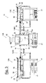
- the plant 10 which continuously effects the multiphase surface treatment of a substrate consisting of a tape 12, comprises at least two controlled pressure chambers 13 arranged in series, in which the successive treatment phases take place.
- Each chamber 13 is marked by its own process conditions, i.e. by a different vacuum degree, with differences between the chambers of even five orders of magnitude, for example typically ranging from 10 3 Pa to 10 -2 Pa, and a different atmosphere, i.e. mixture of treatment gas.
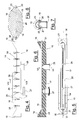
- the chambers 13 are connected to each others by sealed connection units 14, shown in detail in figures 4 to 8, which allow the continuous passage, or running, of the tape 12, but preserve the atmosphere and pressure differences between the chambers 13.
- connection unit 14 cylindrically shaped and connectable at its ends to the vacuum chambers 13 by means of flanges, not shown.
- connection unit 14 comprises a base 15 having cylindrical connection ends 16 and a central semi-cylindrical portion 17, for example made of stainless steel, and a substantially semi-cylindrical cover 18, for example made of aluminum, as shown in the raised view of figure 4.
- the central portion 17 of the base comprises a longitudinal seat 19 for supporting and guiding the tape 12 (figure 5).
- the seat 19 has a height which is greater than the thickness of the tape 12 and comprises a central portion 20 with a greater grooving.
- the seat 19 is connected at each end to a pass-through hole 21, shown in the section of figure 6, produced in the end portions 16 of the base 15 for the passage of the tape 12.
- connection unit 14 runs inside the connection unit 14 with a slight contact friction only on its sides and without rubbing against the walls of the duct, at least on the side on which it is being treated which is facing downwards.
- the cover 18 is equipped with ends having the shape of a flute's mouthpiece 22, which are coupled with complementary tilting surfaces 23 of the base 15.
- a sealing element 24, or O-ring, is situated in a closed-ring groove 25 positioned in the base 15, or alternatively on the cover, on opposite sides of the guiding seat 19 of the tape and on the tilting surfaces 23 (figure 7).
- the sealing element 24 never interferes with the tape 12 and forms a sealing coupling between the base 15 and the cover 18, when they are closed tightly by means of bolts 26.
- connection unit 14 is long and narrow and maximizes the impedance to the gas flow between adjacent chambers.
- connection unit 14 The residual gas flow which, moved by the relative pressure differences at the ends of the connection unit 14, would pass through the connection unit from the chamber 13 having a higher pressure, towards the other chamber 13 with a lower pressure, is intercepted by at least one or more pumping devices connected to the connection unit 14.
- connection unit 14 preferably comprises a first connection 27 to a primary pumping device, or rotary vane pump, and a second connection 28 to a secondary pumping device, or turbomolecular pump, which intercept the gaseous streams at different pressures in two successive points.
- a first primary pumping device facing the higher pressure end, comprises a rotary vane pump with an operating pressure of about 10 3 Pa.
- a secondary pumping device, facing the lower pressure end, comprises a turbomolecular pump, with operating pressures of about 10 -2 Pa, connected for the supply to the primary pump.
- Figures 1 to 3 show an illustrative embodiment of a plant for the production in continuous of a superconducting tape 10 according to the present invention, which effects, for example, a typical surface pre-treatment sequence of the semi-processes metallic tape, the deposition of oxides, for example cerium oxide (CeO 2 ), and surface post-treatment.
- a typical surface pre-treatment sequence of the semi-processes metallic tape the deposition of oxides, for example cerium oxide (CeO 2 )
- surface post-treatment for example cerium oxide (CeO 2 )
- the plant 10 comprises three vacuum chambers 13 arranged in series and connected to each other by two connection units 14, such as those described above.
- a first pre-treatment chamber 13A with a reducing atmosphere consisting of a mixture of argon and hydrogen and a pressure of 10 3 Pa is connected by means of a first connection unit 14AB to a deposition chamber 13B with a reducing atmosphere consisting of a mixture of argon, hydrogen and oxygen and a pressure of 10 -2 Pa, also connected by means of a second connection unit 14BC to a post-treatment chamber 13C with an oxidizing atmosphere consisting of oxygen and a pressure of 10 3 Pa.
- the tape 12 is loaded into the pre-treatment chamber 13A wound on a feeding reel 29, and is re-wound in the post-treatment chamber 13C onto a second winding reel 30. Both reels are equipped with synchronized step-by-step engines 31 in order to keep the linear rate of the tape 12 constant during the activation of the surface treatment process. Friction devices incorporated in the reels 29, 30, not shown, limit the traction force of the tape 12 to pre-established values, correlated to the resistance of the ceramic substrate.
- each chamber 13 comprises a guiding support 32 of the tape 12, comprising two parallel tracks, having a stepped seat, on which the tape runs resting on the two sides.
- Each chamber has cooled walls 35 and cover 36 and comprises heating furnaces 37 to keep the internal temperature at a pre-established value, in the example, 700°C.
- the furnaces 37 shown in figures 1 to 3 are of the known irradiation type and comprise a set of halogen lamps having a length correlated to the duration of the treatment necessary in each chamber 13.
- Temperature control devices 38, or thermocouples, also control the thermal uniformity of the furnaces 37 for their whole length.
- Each of the chambers 13 also comprises a gas inlet valve 39 and an air re-entering valve 40 for the opening of the chambers 13.
- the pre-treatment chambers 13A and post-treatment chambers 13C are equipped with a primary pumping device 41, which can be common to that of the connection unit 14 connected to the respective chamber and connected to the chamber with an interception valve 43.
- the treatment chamber 13B is equipped with a turbomolecular pump 42, or secondary pump, connected for supply to a primary pump 41.
- the production in continuous plant of a superconducting tape 10, object of the present invention must be equipped with a number of primary pumps 41 equal to the number of chambers 13 to avoid the mixing of different atmospheres.
- a coating device 44 for example a crucible, for the evaporation of the coating metal according to a technology of the known type.
- the deposition can be obtained with other known technologies, such as, for example, electronic bombardment.
- the deposition process must take place under high vacuum conditions, controlled by a vacuum gauge 45.
- Each chamber 13 of the plant 10 according to the present invention can in any case be equipped with further instrumentation with respect to that described.
- the surface treatment process of a tape substrate 12 for the production of a superconducting tape 12 is carried out in continuous in a closed plant 10 with respect to the outside environment.
- the process comprises the following phases:
- the deposition of various layers of oxides on the surface of the metallic tape is effected by rewinding the tape 12, at the end of the first surface treatment process, onto the reel 29 in the pre-treatment chamber 13A and repeating the phases described above.
- the plant for the production of a superconducting tape 10 and a relative surface treatment process, object of the present invention have the advantage of producing, with a continuous process, multilayer coated products requiring various deposition phases and thermal treatment under different pressure and atmosphere conditions.
- the solution, object of the present invention allows a drastic cost reduction thanks to the possibility of effecting in situ and with a single passage, a complex deposition process of various thin layers with extremely different physico-chemical characteristics.
Landscapes
- Engineering & Computer Science (AREA)
- General Engineering & Computer Science (AREA)
- Mechanical Engineering (AREA)
- Chemical & Material Sciences (AREA)
- Manufacturing & Machinery (AREA)
- Chemical Kinetics & Catalysis (AREA)
- Materials Engineering (AREA)
- Metallurgy (AREA)
- Organic Chemistry (AREA)
- Superconductors And Manufacturing Methods Therefor (AREA)
- Physical Vapour Deposition (AREA)
- Inorganic Compounds Of Heavy Metals (AREA)
Priority Applications (3)
| Application Number | Priority Date | Filing Date | Title |
|---|---|---|---|
| AT05113039T ATE475993T1 (de) | 2005-12-28 | 2005-12-28 | Anlage zur kontinuierlichen herstellung eines supraleiterbandes |
| DE602005022604T DE602005022604D1 (de) | 2005-12-28 | 2005-12-28 | Anlage zur kontinuierlichen Herstellung eines Supraleiterbandes |
| EP05113039A EP1804306B1 (fr) | 2005-12-28 | 2005-12-28 | Installation pour la production en continu d'une bande supraconductrice |
Applications Claiming Priority (1)
| Application Number | Priority Date | Filing Date | Title |
|---|---|---|---|
| EP05113039A EP1804306B1 (fr) | 2005-12-28 | 2005-12-28 | Installation pour la production en continu d'une bande supraconductrice |
Publications (2)
| Publication Number | Publication Date |
|---|---|
| EP1804306A1 true EP1804306A1 (fr) | 2007-07-04 |
| EP1804306B1 EP1804306B1 (fr) | 2010-07-28 |
Family
ID=36581841
Family Applications (1)
| Application Number | Title | Priority Date | Filing Date |
|---|---|---|---|
| EP05113039A Expired - Lifetime EP1804306B1 (fr) | 2005-12-28 | 2005-12-28 | Installation pour la production en continu d'une bande supraconductrice |
Country Status (3)
| Country | Link |
|---|---|
| EP (1) | EP1804306B1 (fr) |
| AT (1) | ATE475993T1 (fr) |
| DE (1) | DE602005022604D1 (fr) |
Cited By (5)
| Publication number | Priority date | Publication date | Assignee | Title |
|---|---|---|---|---|
| CN104236991A (zh) * | 2014-08-19 | 2014-12-24 | 宁波英飞迈材料科技有限公司 | 一种可拆卸原位热处理装置及其使用方法 |
| CN105970174A (zh) * | 2016-06-14 | 2016-09-28 | 肇庆市大力真空设备有限公司 | 一种快速的真空磁控溅射镀膜设备及其加工方法 |
| CN109402596A (zh) * | 2018-10-29 | 2019-03-01 | 厦门建霖健康家居股份有限公司 | 一种连续型真空多彩镀膜系统 |
| CN111519159A (zh) * | 2020-04-30 | 2020-08-11 | 绍兴市宇德塑料制品有限公司 | 一种多适用规格的塑料制品真空镀膜设备 |
| CN116641037A (zh) * | 2023-07-27 | 2023-08-25 | 上海超导科技股份有限公司 | 双面镀制超导带材保护层的设备 |
Citations (4)
| Publication number | Priority date | Publication date | Assignee | Title |
|---|---|---|---|---|
| GB766459A (en) * | 1953-05-15 | 1957-01-23 | Heraeus Gmbh W C | Improvements in or relating to high-vacuum coating devices |
| FR1545284A (fr) * | 1967-11-24 | 1968-11-08 | Hochvakuum Dresden Veb | Dispositif de projection par vaporisation sur des bandes |
| EP0305573A1 (fr) * | 1987-09-03 | 1989-03-08 | Nippon Steel Corporation | Appareil pour appliquer en continu un revêtement composite sur un ruban |
| WO2004012278A2 (fr) * | 2002-07-26 | 2004-02-05 | Metal Oxide Technologies Inc. | Procede et appareil permettant le depot d'un materiau supraconducteur sur un substrat en bande |
-
2005
- 2005-12-28 AT AT05113039T patent/ATE475993T1/de not_active IP Right Cessation
- 2005-12-28 DE DE602005022604T patent/DE602005022604D1/de not_active Expired - Lifetime
- 2005-12-28 EP EP05113039A patent/EP1804306B1/fr not_active Expired - Lifetime
Patent Citations (4)
| Publication number | Priority date | Publication date | Assignee | Title |
|---|---|---|---|---|
| GB766459A (en) * | 1953-05-15 | 1957-01-23 | Heraeus Gmbh W C | Improvements in or relating to high-vacuum coating devices |
| FR1545284A (fr) * | 1967-11-24 | 1968-11-08 | Hochvakuum Dresden Veb | Dispositif de projection par vaporisation sur des bandes |
| EP0305573A1 (fr) * | 1987-09-03 | 1989-03-08 | Nippon Steel Corporation | Appareil pour appliquer en continu un revêtement composite sur un ruban |
| WO2004012278A2 (fr) * | 2002-07-26 | 2004-02-05 | Metal Oxide Technologies Inc. | Procede et appareil permettant le depot d'un materiau supraconducteur sur un substrat en bande |
Cited By (6)
| Publication number | Priority date | Publication date | Assignee | Title |
|---|---|---|---|---|
| CN104236991A (zh) * | 2014-08-19 | 2014-12-24 | 宁波英飞迈材料科技有限公司 | 一种可拆卸原位热处理装置及其使用方法 |
| CN105970174A (zh) * | 2016-06-14 | 2016-09-28 | 肇庆市大力真空设备有限公司 | 一种快速的真空磁控溅射镀膜设备及其加工方法 |
| CN109402596A (zh) * | 2018-10-29 | 2019-03-01 | 厦门建霖健康家居股份有限公司 | 一种连续型真空多彩镀膜系统 |
| CN111519159A (zh) * | 2020-04-30 | 2020-08-11 | 绍兴市宇德塑料制品有限公司 | 一种多适用规格的塑料制品真空镀膜设备 |
| CN116641037A (zh) * | 2023-07-27 | 2023-08-25 | 上海超导科技股份有限公司 | 双面镀制超导带材保护层的设备 |
| CN116641037B (zh) * | 2023-07-27 | 2023-10-20 | 上海超导科技股份有限公司 | 双面镀制超导带材保护层的设备 |
Also Published As
| Publication number | Publication date |
|---|---|
| ATE475993T1 (de) | 2010-08-15 |
| EP1804306B1 (fr) | 2010-07-28 |
| DE602005022604D1 (de) | 2010-09-09 |
Similar Documents
| Publication | Publication Date | Title |
|---|---|---|
| EP2000008B1 (fr) | Dispositif et procede de depot en couches atomiques pour revetement de substrats flexibles | |
| US7085616B2 (en) | Atomic layer deposition apparatus | |
| EP2354272B1 (fr) | Appareil pour le revêtement de la surface interne et externe d'un tube enroulé en continu et procédé de revêtement avec du graphène utilisant cet appareil | |
| US20150368789A1 (en) | Method and arrangement for providing chalcogens | |
| WO2002015243A1 (fr) | Dispositif et traitement de substrat | |
| JP3354747B2 (ja) | Cvd反応装置および酸化物超電導導体の製造方法 | |
| US20120258863A1 (en) | Metalorganic chemical vapor deposition (mocvd) process and apparatus to produce multi-layer high-temperature superconducting (hts) coated tape | |
| CN103025918B (zh) | 用于在基质上制造超导层的方法和设备 | |
| KR20120109989A (ko) | 웹 기판 증착 시스템 | |
| KR20190041506A (ko) | 롤 투 롤 방식의 표면 처리 장치 그리고 이것을 사용한 성막 방법 및 성막 장치 | |
| US20130164445A1 (en) | Self-Contained Heating Element | |
| US8268386B2 (en) | Method for manufacturing high-temperature superconducting conductors | |
| EP1804306A1 (fr) | Installation pour la production en continu d'une bande supraconductrice et procédé de traitement de surface correspondant | |
| JP2019104951A (ja) | 長尺基板の処理装置と処理方法 | |
| US20040178175A1 (en) | Atomic layer deposition for high temperature superconductor material synthesis | |
| JP5849934B2 (ja) | 真空成膜装置と真空成膜方法 | |
| JP3741861B2 (ja) | Cvd反応装置 | |
| JP3808250B2 (ja) | Cvd反応装置及び酸化物超電導体の製造方法 | |
| JP3880708B2 (ja) | 酸化物超電導体の製造装置および製造方法 | |
| JP3771142B2 (ja) | 酸化物超電導導体及びその製造方法 | |
| US8124171B2 (en) | Method of and apparatus for manufacturing tape-formed oxide superconductor | |
| JP3756322B2 (ja) | 酸化物超電導導体の製造装置および製造方法 | |
| JP3771107B2 (ja) | 酸化物超電導導体及びその製造装置並びに製造方法 | |
| JP4112314B2 (ja) | 酸化物超電導導体製造cvd反応装置用液体原料供給装置及び酸化物超電導導体の製造方法 | |
| JP2013147723A (ja) | 超電導線材の製造装置及び製造方法 |
Legal Events
| Date | Code | Title | Description |
|---|---|---|---|
| PUAI | Public reference made under article 153(3) epc to a published international application that has entered the european phase |
Free format text: ORIGINAL CODE: 0009012 |
|
| AK | Designated contracting states |
Kind code of ref document: A1 Designated state(s): AT BE BG CH CY CZ DE DK EE ES FI FR GB GR HU IE IS IT LI LT LU LV MC NL PL PT RO SE SI SK TR |
|
| AX | Request for extension of the european patent |
Extension state: AL BA HR MK YU |
|
| 17P | Request for examination filed |
Effective date: 20051228 |
|
| AKX | Designation fees paid |
Designated state(s): AT BE BG CH CY CZ DE DK EE ES FI FR GB GR HU IE IS IT LI LT LU LV MC NL PL PT RO SE SI SK TR |
|
| 17Q | First examination report despatched |
Effective date: 20080326 |
|
| RTI1 | Title (correction) |
Free format text: PLANT FOR THE PRODUCTION IN CONTINUOUS OF A SUPERCONDUCTING TAPE |
|
| GRAP | Despatch of communication of intention to grant a patent |
Free format text: ORIGINAL CODE: EPIDOSNIGR1 |
|
| RIN1 | Information on inventor provided before grant (corrected) |
Inventor name: CANETTI, MARCO Inventor name: BATTOCCHIO, ALESSANDRO |
|
| GRAS | Grant fee paid |
Free format text: ORIGINAL CODE: EPIDOSNIGR3 |
|
| GRAA | (expected) grant |
Free format text: ORIGINAL CODE: 0009210 |
|
| AK | Designated contracting states |
Kind code of ref document: B1 Designated state(s): AT BE BG CH CY CZ DE DK EE ES FI FR GB GR HU IE IS IT LI LT LU LV MC NL PL PT RO SE SI SK TR |
|
| REG | Reference to a national code |
Ref country code: GB Ref legal event code: FG4D |
|
| REG | Reference to a national code |
Ref country code: CH Ref legal event code: EP |
|
| REG | Reference to a national code |
Ref country code: IE Ref legal event code: FG4D |
|
| REF | Corresponds to: |
Ref document number: 602005022604 Country of ref document: DE Date of ref document: 20100909 Kind code of ref document: P |
|
| REG | Reference to a national code |
Ref country code: NL Ref legal event code: VDEP Effective date: 20100728 |
|
| LTIE | Lt: invalidation of european patent or patent extension |
Effective date: 20100728 |
|
| PG25 | Lapsed in a contracting state [announced via postgrant information from national office to epo] |
Ref country code: LT Free format text: LAPSE BECAUSE OF FAILURE TO SUBMIT A TRANSLATION OF THE DESCRIPTION OR TO PAY THE FEE WITHIN THE PRESCRIBED TIME-LIMIT Effective date: 20100728 Ref country code: NL Free format text: LAPSE BECAUSE OF FAILURE TO SUBMIT A TRANSLATION OF THE DESCRIPTION OR TO PAY THE FEE WITHIN THE PRESCRIBED TIME-LIMIT Effective date: 20100728 Ref country code: FI Free format text: LAPSE BECAUSE OF FAILURE TO SUBMIT A TRANSLATION OF THE DESCRIPTION OR TO PAY THE FEE WITHIN THE PRESCRIBED TIME-LIMIT Effective date: 20100728 Ref country code: AT Free format text: LAPSE BECAUSE OF FAILURE TO SUBMIT A TRANSLATION OF THE DESCRIPTION OR TO PAY THE FEE WITHIN THE PRESCRIBED TIME-LIMIT Effective date: 20100728 |
|
| PG25 | Lapsed in a contracting state [announced via postgrant information from national office to epo] |
Ref country code: CY Free format text: LAPSE BECAUSE OF FAILURE TO SUBMIT A TRANSLATION OF THE DESCRIPTION OR TO PAY THE FEE WITHIN THE PRESCRIBED TIME-LIMIT Effective date: 20100728 Ref country code: BG Free format text: LAPSE BECAUSE OF FAILURE TO SUBMIT A TRANSLATION OF THE DESCRIPTION OR TO PAY THE FEE WITHIN THE PRESCRIBED TIME-LIMIT Effective date: 20101028 Ref country code: IS Free format text: LAPSE BECAUSE OF FAILURE TO SUBMIT A TRANSLATION OF THE DESCRIPTION OR TO PAY THE FEE WITHIN THE PRESCRIBED TIME-LIMIT Effective date: 20101128 Ref country code: SI Free format text: LAPSE BECAUSE OF FAILURE TO SUBMIT A TRANSLATION OF THE DESCRIPTION OR TO PAY THE FEE WITHIN THE PRESCRIBED TIME-LIMIT Effective date: 20100728 Ref country code: PT Free format text: LAPSE BECAUSE OF FAILURE TO SUBMIT A TRANSLATION OF THE DESCRIPTION OR TO PAY THE FEE WITHIN THE PRESCRIBED TIME-LIMIT Effective date: 20101129 Ref country code: PL Free format text: LAPSE BECAUSE OF FAILURE TO SUBMIT A TRANSLATION OF THE DESCRIPTION OR TO PAY THE FEE WITHIN THE PRESCRIBED TIME-LIMIT Effective date: 20100728 |
|
| PG25 | Lapsed in a contracting state [announced via postgrant information from national office to epo] |
Ref country code: SE Free format text: LAPSE BECAUSE OF FAILURE TO SUBMIT A TRANSLATION OF THE DESCRIPTION OR TO PAY THE FEE WITHIN THE PRESCRIBED TIME-LIMIT Effective date: 20100728 Ref country code: LV Free format text: LAPSE BECAUSE OF FAILURE TO SUBMIT A TRANSLATION OF THE DESCRIPTION OR TO PAY THE FEE WITHIN THE PRESCRIBED TIME-LIMIT Effective date: 20100728 Ref country code: BE Free format text: LAPSE BECAUSE OF FAILURE TO SUBMIT A TRANSLATION OF THE DESCRIPTION OR TO PAY THE FEE WITHIN THE PRESCRIBED TIME-LIMIT Effective date: 20100728 Ref country code: GR Free format text: LAPSE BECAUSE OF FAILURE TO SUBMIT A TRANSLATION OF THE DESCRIPTION OR TO PAY THE FEE WITHIN THE PRESCRIBED TIME-LIMIT Effective date: 20101029 |
|
| PGFP | Annual fee paid to national office [announced via postgrant information from national office to epo] |
Ref country code: IT Payment date: 20101120 Year of fee payment: 6 |
|
| PG25 | Lapsed in a contracting state [announced via postgrant information from national office to epo] |
Ref country code: DK Free format text: LAPSE BECAUSE OF FAILURE TO SUBMIT A TRANSLATION OF THE DESCRIPTION OR TO PAY THE FEE WITHIN THE PRESCRIBED TIME-LIMIT Effective date: 20100728 |
|
| PG25 | Lapsed in a contracting state [announced via postgrant information from national office to epo] |
Ref country code: EE Free format text: LAPSE BECAUSE OF FAILURE TO SUBMIT A TRANSLATION OF THE DESCRIPTION OR TO PAY THE FEE WITHIN THE PRESCRIBED TIME-LIMIT Effective date: 20100728 Ref country code: RO Free format text: LAPSE BECAUSE OF FAILURE TO SUBMIT A TRANSLATION OF THE DESCRIPTION OR TO PAY THE FEE WITHIN THE PRESCRIBED TIME-LIMIT Effective date: 20100728 Ref country code: CZ Free format text: LAPSE BECAUSE OF FAILURE TO SUBMIT A TRANSLATION OF THE DESCRIPTION OR TO PAY THE FEE WITHIN THE PRESCRIBED TIME-LIMIT Effective date: 20100728 Ref country code: SK Free format text: LAPSE BECAUSE OF FAILURE TO SUBMIT A TRANSLATION OF THE DESCRIPTION OR TO PAY THE FEE WITHIN THE PRESCRIBED TIME-LIMIT Effective date: 20100728 |
|
| PLBE | No opposition filed within time limit |
Free format text: ORIGINAL CODE: 0009261 |
|
| STAA | Information on the status of an ep patent application or granted ep patent |
Free format text: STATUS: NO OPPOSITION FILED WITHIN TIME LIMIT |
|
| PG25 | Lapsed in a contracting state [announced via postgrant information from national office to epo] |
Ref country code: ES Free format text: LAPSE BECAUSE OF FAILURE TO SUBMIT A TRANSLATION OF THE DESCRIPTION OR TO PAY THE FEE WITHIN THE PRESCRIBED TIME-LIMIT Effective date: 20101108 |
|
| 26N | No opposition filed |
Effective date: 20110429 |
|
| PG25 | Lapsed in a contracting state [announced via postgrant information from national office to epo] |
Ref country code: MC Free format text: LAPSE BECAUSE OF NON-PAYMENT OF DUE FEES Effective date: 20101231 |
|
| REG | Reference to a national code |
Ref country code: CH Ref legal event code: PL |
|
| GBPC | Gb: european patent ceased through non-payment of renewal fee |
Effective date: 20101228 |
|
| REG | Reference to a national code |
Ref country code: DE Ref legal event code: R097 Ref document number: 602005022604 Country of ref document: DE Effective date: 20110429 |
|
| REG | Reference to a national code |
Ref country code: FR Ref legal event code: ST Effective date: 20110831 |
|
| PG25 | Lapsed in a contracting state [announced via postgrant information from national office to epo] |
Ref country code: IE Free format text: LAPSE BECAUSE OF NON-PAYMENT OF DUE FEES Effective date: 20101228 Ref country code: FR Free format text: LAPSE BECAUSE OF NON-PAYMENT OF DUE FEES Effective date: 20110103 Ref country code: CH Free format text: LAPSE BECAUSE OF NON-PAYMENT OF DUE FEES Effective date: 20101231 Ref country code: LI Free format text: LAPSE BECAUSE OF NON-PAYMENT OF DUE FEES Effective date: 20101231 |
|
| PG25 | Lapsed in a contracting state [announced via postgrant information from national office to epo] |
Ref country code: GB Free format text: LAPSE BECAUSE OF NON-PAYMENT OF DUE FEES Effective date: 20101228 |
|
| PGFP | Annual fee paid to national office [announced via postgrant information from national office to epo] |
Ref country code: DE Payment date: 20111221 Year of fee payment: 7 |
|
| PG25 | Lapsed in a contracting state [announced via postgrant information from national office to epo] |
Ref country code: HU Free format text: LAPSE BECAUSE OF FAILURE TO SUBMIT A TRANSLATION OF THE DESCRIPTION OR TO PAY THE FEE WITHIN THE PRESCRIBED TIME-LIMIT Effective date: 20110129 Ref country code: LU Free format text: LAPSE BECAUSE OF NON-PAYMENT OF DUE FEES Effective date: 20101228 |
|
| PG25 | Lapsed in a contracting state [announced via postgrant information from national office to epo] |
Ref country code: TR Free format text: LAPSE BECAUSE OF FAILURE TO SUBMIT A TRANSLATION OF THE DESCRIPTION OR TO PAY THE FEE WITHIN THE PRESCRIBED TIME-LIMIT Effective date: 20100728 |
|
| PG25 | Lapsed in a contracting state [announced via postgrant information from national office to epo] |
Ref country code: IT Free format text: LAPSE BECAUSE OF NON-PAYMENT OF DUE FEES Effective date: 20111228 |
|
| PG25 | Lapsed in a contracting state [announced via postgrant information from national office to epo] |
Ref country code: DE Free format text: LAPSE BECAUSE OF NON-PAYMENT OF DUE FEES Effective date: 20130702 |
|
| REG | Reference to a national code |
Ref country code: DE Ref legal event code: R119 Ref document number: 602005022604 Country of ref document: DE Effective date: 20130702 |