EP1805073B1 - Kupplungskopf mit lösbarer stirnplatte, für schienenfahrzeuge, sowie dazugehöriges montageverfahren. - Google Patents
Kupplungskopf mit lösbarer stirnplatte, für schienenfahrzeuge, sowie dazugehöriges montageverfahren. Download PDFInfo
- Publication number
- EP1805073B1 EP1805073B1 EP05778101A EP05778101A EP1805073B1 EP 1805073 B1 EP1805073 B1 EP 1805073B1 EP 05778101 A EP05778101 A EP 05778101A EP 05778101 A EP05778101 A EP 05778101A EP 1805073 B1 EP1805073 B1 EP 1805073B1
- Authority
- EP
- European Patent Office
- Prior art keywords
- coupler head
- head housing
- coupling head
- face plate
- housing
- Prior art date
- Legal status (The legal status is an assumption and is not a legal conclusion. Google has not performed a legal analysis and makes no representation as to the accuracy of the status listed.)
- Expired - Lifetime
Links
Images

Classifications
-
- B—PERFORMING OPERATIONS; TRANSPORTING
- B61—RAILWAYS
- B61G—COUPLINGS; DRAUGHT AND BUFFING APPLIANCES
- B61G3/00—Couplings comprising mating parts of similar shape or form which can be coupled without the use of any additional element or elements
- B61G3/16—Couplings comprising mating parts of similar shape or form which can be coupled without the use of any additional element or elements with coupling heads rigidly connected by rotatable hook plates or discs and balancing links, the coupling members forming a parallelogram, e.g. "Scharfenberg" type
-
- B—PERFORMING OPERATIONS; TRANSPORTING
- B61—RAILWAYS
- B61G—COUPLINGS; DRAUGHT AND BUFFING APPLIANCES
- B61G1/00—Couplings comprising interengaging parts of different shape or form and having links, bars, pins, shackles, or hooks as coupling means
-
- B—PERFORMING OPERATIONS; TRANSPORTING
- B61—RAILWAYS
- B61G—COUPLINGS; DRAUGHT AND BUFFING APPLIANCES
- B61G7/00—Details or accessories
Definitions
- the present invention relates to a coupling head for detachable vehicles with a coupling head housing and with an end face of the coupling head housing end face.
- the present invention further relates to an assembly method for such a coupling head.
- Coupling head housing for detachable vehicles are described several times in technical and patent literature.
- the publication DE 43 12 405 A1 describes, for example, a central buffer coupling for rail vehicles, which additionally contains a protective device.
- a full-line clutch called type 10.
- This full-line coupling head is characterized by a large gripping area in side and height. This is made possible by the use of a gripper and a jib. This characteristic guarantees universal applicability.
- the full-track type 10 coupling head is used throughout Europe by almost all state railways and worldwide, for example in Asia, Australia and South Africa. Material selection and design of the head and the closure elements are optimally designed for the transmission of the tensile and compressive forces required in the UIC guidelines and proven by type tests. If necessary, the front plate can be equipped with a heater for trouble-free winter operation.
- metro couplings are known that can be used by light rail vehicles to metro trains.
- central buffer couplings and coupling head housings have in common that they are each designed and manufactured as a whole.
- the publication DE 11 24 535 B describes, for example, a housing for automatic rigid central buffer couplings consisting of a face plate with a pyramidal projection and a corresponding recess on the buffer surface, an end piece for connecting the housing with a coupling rod and a lying between the face plate and the end actual housing body, the cell in construction of individual Moldings is composed. It is envisaged that both the end plate and the tail made of a forging or casting and held together by connectors.
- this known from the prior art structure requires that the coupling and the coupling head housing are constructed and manufactured as a whole.
- Modular concepts for coupling heads are not yet known.
- each housing part there is an end plate, which is fixed, ie not detachable, connected to the rest of the coupling head housing, for example, by the end plate welded to the remaining coupling head housing or formed in one piece.
- the housings were formed by upper and lower housing half shells. After that, you went over to that Make coupling head housing in one piece. Thereafter, the face plate was welded to the coupling head housing. Due to the welding and the associated thermal expansion, it has not been possible to install all holes, grooves and recesses before welding. Rather, the entire coupling head had to be reworked after welding together in detail. In particular, holes and grooves had to be added later.
- the present invention seeks to further develop known from the prior art coupling head housing for rail vehicles with Stirnplattem the shape that a modular design is possible and face plates can be mounted on various rear clutch housing.
- This type of construction of a coupling head offers a number of advantages over the conventional welded-together coupling heads. Due to the detachable connection between the coupling head housing and the front plate, the properties of the coupling head and its manufacturing process are optimized as a whole. It can be said of a modular concept in which different coupling head housing can be mounted on turn different face plates. A holistic design and a holistic production of the complete coupling head is no longer necessary. Also, the faceplate for maintenance or repair work inside the coupling head housing can be removed, so that service personnel can easily approach the Entkuppelzylinder and the other parts of the complete coupling closure.
- the coupling head housing has no design features related only to a coupling head type. These coupling head type related design features are placed on, in or on the faceplate.
- coupling head type-related design features are meant all major design features common to one type of coupling head and characterizing the type of coupling head. For example, the determination of the gripping area or the size and / or shape of the hopper and cone is such a coupling head type-related design feature, as this feature is characteristic of the closure of the coupling head.
- a compensation element is positioned between the coupling head housing and the end plate.
- This compensating element can compensate for a variety of strengths including manufacturing tolerances and a coupling clearance.
- the compensation element can serve to separate different materials of the coupling head housing and the face plate.
- the compensation element is preferably shaped so that it substantially corresponds to the cross-sectional geometry of the end face of the coupling head housing, similar to a seal.
- the compensation element is not limited exclusively to the cross-sectional geometry of the end face of the coupling head housing. It can protrude on both sides, ie inwards as well as outwards, beyond the edge of the end face of the coupling head housing. With the compensation element can be a number of other functions that are described below, realize.
- a number of spacer elements for example in the form of several compared to the compensation element smaller washers, are used, for example, at the below-mentioned connecting elements between the coupling head housing and end plate substantially be arranged small area or even punctually.
- the compensation element consists of plastic, which of course other materials, such. As metal or multi-component materials are conceivable.
- the compensation element or the number of spacer elements can then ensure the function of compensation of manufacturing tolerances also for a separation of possible different materials of face plate and coupling head housing.
- the use of different materials for the compensation element also allows different pressure and sound transmission properties of the face plate to the coupling head housing. This results in an additional adjustable damping effect during the coupling between the face plate and the coupling head housing. This damping effect also ensures a noise reduction during the coupling process. In the case of passenger cars, this means a further reduction in the level of noise when clutching and driving, and a concomitant reduction in the noise of passengers traveling along. But of course, a compensation element made of classic metal is conceivable.
- the coupling head housing consists of one piece. It would be conceivable here, for example, that the coupling head housing is designed as a welded housing. Of course, but also differently designed in one piece coupling head housing conceivable.
- the coupling head housing made of glass-fiber-reinforced material, in particular fiberglass-reinforced carbon fiber material or similar composites.
- glass-fiber-reinforced material in particular fiberglass-reinforced carbon fiber material or similar composites.
- the use of these materials offers over the conventional metal a number of advantages such as very high weathering and corrosion resistance, electrical insulation and positive, since low noise conduction properties that act on a dome operation and overall ride on noise reduction.
- Another advantage to using glass fiber reinforced materials, especially glass fiber reinforced carbon fiber material is in weight reduction, which is a major factor in couplings.
- a coupling head housing made of metal. It can for example be made of investment casting material. In this case, conventional manufacturing methods are used. A conversion of the manufacturing process of the coupling head housing in the implementation of the present invention is not required here.
- the end plate of precision casting material.
- This has the significant advantage that many holes, grooves and recesses can be mounted in a manufacturing process on the face plate. As a result, processing steps can be saved.
- the face plate can be made differently, for example, from normal casting material or by forging and casting other suitable materials.
- the end plate is made of a non-metallic material.
- the back of the end plate on recesses in the form of grooves.
- These heating elements ensure that the front plate and thus the coupling head can be heated in harsh winter operation, so that, for example, snow or ice can be defrosted.
- These heating elements have been previously mounted in subsequently milled grooves or holes. These grooves were then subsequently closed again with brazing. Also, this complex individual process in the production is eliminated by the inventively proposed construction of the coupling head.
- the face plate can be mounted by means of screws to the coupling head housing.
- the compensation element is located between the coupling head housing and the end plate.
- Virtually any type of fasteners may be used to mount the face plate to the coupling housing. Cylinder head bolts or countersunk screws are one possible embodiment. The screws can either engage in prefabricated thread of the coupling head housing or be designed as a stud. This stud would then protrude through the face plate and a hole in the form of an eyelet in the coupling head housing to be fixed from the back with a nut.
- the object underlying the present invention is also achieved according to the invention by a method for mounting a coupling head with the following method steps. If heating elements are provided in the coupling head, they are first inserted into the grooves of the face plate. Then, if necessary, the compensation element is inserted into the face plate or applied to the face plate. The decoupling cylinder and the complete coupling closure have already been pre-assembled in the coupling housing. The thus preassembled face plate and the preassembled coupling head housing are then assembled by means of screws and fastened together. Welding is no longer necessary with this type of assembly of the coupling head. Longer cooling times and reworking needs of the coupling head are eliminated. As a result, potential sources of error in the manufacturing process can be eliminated, so that the coupling head can be manufactured with higher production quality.
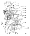
- Fig. 1 shows a possible construction of a coupling head 1 in a modular design. It consists of the two essential components end plate 4 and the actual coupling head housing 2. Between the coupling head housing 2 and the end plate 4, a compensating element 6 may be provided. This compensating element 6 serves to compensate for differences between the end face of the coupling head housing 2 and the end plate 4 if necessary. As compensation element can, as in Fig. 1 shown, a balance plate 6 can be used. It is also conceivable, in addition to the compensating plate or alternatively (not explicitly shown) spacer elements, for example in the form of washers to use. Of course, the compensation elements and spacers are not essential components of the device according to the invention.
- heating elements 9, 11, 13, 15, which are positioned between the coupling head housing 2 and the end plate 4.
- connecting elements - for example, cylindrical screws 5, which pass through holes 16 in the end plate 4 - the face plate 4 is mounted together with the compensating element 6 used in the illustrated embodiment of the coupling head housing.
- the parts lie positively against one another.
- the coupling members 7, 17, in particular the decoupling cylinder and the coupling closure are already mounted in the coupling head housing 2.
- Fig. 2 shows the grooves 10, 12, 14 provided in the end plate 4 for receiving the heating elements 9, 11, 13, 15.
- the groove for the heating element 9 is concealed in this illustration and therefore not visible.
- the compensating element 6 may consist of eg metal or plastic, for example, wherein plastic brings the benefits of a damping effect and a separation of different materials of face plate 4 and coupling head housing 2 with it.
- the heating elements 9, 11, 13, 15 inserted into the grooves 10, 12, 14 of the end plate 4.
- the compensation element 6 is applied to the end plate.
- the coupling members 7, 17 are installed in the still open coupling head housing.
- the pre-assembled parts are now by means of screws 5, which are guided through holes 16 of the face plate 4 and corresponding holes in the compensating element 6, assembled by the screws are screwed into corresponding threads in the coupling head housing 2. It is not necessarily so that the coupling members 7, 17 are installed in the coupling head housing prior to assembly. This process step can also be done after joining the face plate 4 and the empty coupling head housing 2.
- the heating elements 9, 11, 13, 15 are inserted into the grooves 10, 12, 14 of the end plate 4, wherein subsequently the coupling members 7, 17 can be installed in the still open coupling head housing.
- the thus pre-assembled parts are then assembled with the screws 5 in the manner already described above, namely by the screws are screwed into corresponding threads in the coupling head housing 2.
Landscapes
- Engineering & Computer Science (AREA)
- Mechanical Engineering (AREA)
- Connection Of Plates (AREA)
- Electric Propulsion And Braking For Vehicles (AREA)
- Handcart (AREA)
- Body Structure For Vehicles (AREA)
- Machines For Laying And Maintaining Railways (AREA)
- Fittings On The Vehicle Exterior For Carrying Loads, And Devices For Holding Or Mounting Articles (AREA)
- Lighting Device Outwards From Vehicle And Optical Signal (AREA)
- Toys (AREA)
- Automobile Manufacture Line, Endless Track Vehicle, Trailer (AREA)
- Investigating Or Analyzing Materials By The Use Of Ultrasonic Waves (AREA)
Description
- Die vorliegende Erfindung betrifft einen Kupplungskopf für kuppelbare Fahrzeuge mit einem Kupplungskopfgehäuse und mit einer an das Kupplungskopfgehäuse stirnseitig abschließenden Stirnplatte. Die vorliegende Erfindung betrifft des weiteren ein Montageverfahren für einen derartigen Kupplungskopf.
- Kupplungskopfgehäuse für kuppelbare Fahrzeuge sind in Fach- und Patentliteratur mehrfach beschrieben. Die Druckschrift
DE 43 12 405 A1 beschreibt beispielsweise eine Mittelpufferkupplung für Schienenfahrzeuge, die zusätzlich eine Schutzvorrichtung enthält. - Weiterhin ist aus der Druckschrift
DE 82 10 877 eine elektrische Heizung für Mittelpufferkupplungen bekannt. Heizungen werden in Mittelpufferkupplungen eingebaut, um auch im winterlichen Betrieb eine einwandfreie Funktion zu gewährleisten. Insbesondere sollen die integrierten Heizungen dafür sorgen, dass die vorderen Stirnplatten eis- und schneefrei bleiben, um eine sichere Funktion des Kupplungsvorganges sicherzustellen. Auch die DruckschriftUS 6,008,472 beschreibt das Einbringen von Heizelementen in die Stirnplatte von Kupplungskopfgehäusen am Beispiel einer Scharfenberg-Mittelpufferkupplung. - In Bezug auf die vorliegende Erfindung sind - exemplarisch, aber nicht ausschließlich - drei wesentliche Kupplungen vom Typ Scharfenberg bekannt: Eine Vollbahnkupplung namens Typ 10. Dieser Vollbahn-Kupplungskopf zeichnet sich durch einen großen Greifbereich in Seite und Höhe aus. Ermöglicht wird dies durch die Verwendung eines Greifers und eines Auslegers. Diese Charakteristik garantiert universelle Einsetzbarkeit. Der Vollbahn-Kupplungskopf Typ 10 wird europaweit von nahezu allen Staatsbahnen und weltweit, zum Beispiel in Asien, Australien und Südafrika, eingesetzt. Materialauswahl und Ausgestaltung des Kopfes und der Verschlusselemente sind für die Übertragung der in den UIC-Richtlinien geforderten Zug- und Druckkräfte optimal ausgelegt und durch Typentests nachgewiesen. Falls notwendig lässt sich die Stirnplatte für einen störungsfreien Winterbetrieb mit einer Heizung ausstatten. Weiterhin sind Metrokupplungen bekannt, die sich von Stadtbahnen bis zu Metro-Zügen einsetzen lassen.
- Den meisten bisherigen bekannten Konstruktionen von Mittelpufferkupplungen und Kupplungskopfgehäusen ist allerdings gemeinsam, dass sie jeweils als Gesamtheit konstruiert und gefertigt sind. Die Druckschrift
DE 11 24 535 B beschreibt beispielsweise ein Gehäuse für selbsttätige starre Mittelpufferkupplungen bestehend aus einer Stirnplatte mit einem pyramidenförmigen Vorsprung und einer entsprechenden Vertiefung an der Pufferfläche, einem Endstück zur Verbindung des Gehäuses mit einer Kupplungsstange und einem zwischen der Stirnplatte und dem Endstück liegenden eigentlichen Gehäusekörper, der in Zellenbauweise aus einzelnen Formteilen zusammengesetzt ist. Dabei ist vorgesehen, dass sowohl die Stirnplatte als auch das Endstück aus einem Schmiede- oder Gussstück hergestellt und durch Verbindungsstücke zusammengehalten ist. Dieser aus dem Stand der Technik bekannte Aufbau bedingt allerdings, dass die Kupplung und das Kupplungskopfgehäuse als Gesamtheit konstruiert und gefertigt sind. - Aus den Wartungsunterlagen "Maintenance Manual of Central Line 1990 Tubestock, Volume 02, Chapter 1, Part I, page 24, FIG 10" ist jedoch eine Mittelpuferkupplung bekannt, bei der die Stirnplatte mittels Schrauben an dem Kupplungskopfgehause befestigt wird.
- Obwohl die Erfindung unter Bezugnahme auf Kupplungsköpfe für Schienenfahrzeuge exemplarisch beschrieben wird, sei an dieser Stelle ausdrücklich darauf hingewiesen, dass sich die Erfindung auf Kupplungsköpfe allgemein bezieht. Demnach fallen auch Kupplungsköpfe für beispielsweise Fahrzeugkupplungen oder für Magnetschwebebahnen hierunter. In der vorliegenden Spezifikation wurde von daher der Ausdruck "Kupplungskopf für kuppelbare Fahrzeuge" gewählt.
- Modulare Konzepte für Kupplungsköpfe sind bisher nicht bekannt. Zu jedem Gehäuseteil gibt es eine Stirnplatte, die fest, d.h. nicht lösbar, mit dem restlichen Kupplungskopfgehäuse verbunden ist, beispielsweise indem die Stirnplatte mit dem restlichen Kupplungskopfgehäuse verschweißt oder einstückig ausgebildet ist. In den Anfängen der Kupplungskopfgehäuse wurden die Gehäuse durch eine obere und untere Gehäusehalbschale geformt. Danach ist man dazu übergegangen, das Kupplungskopfgehäuse in einem Stück herzustellen. Danach wurde die Stirnplatte auf das Kupplungskopfgehäuse aufgeschweißt. Bedingt durch das Schweißen und die damit verbundenen Wärmeausdehnungen ist es bisher nicht möglich, alle Bohrungen, Nuten und Aussparungen vor dem Verschweißen anzubringen. Vielmehr musste der komplette Kupplungskopf nach dem Zusammenschweißen im Detail nachbearbeitet werden. Insbesondere mussten Bohrungen und Nuten nachträglich angebracht werden. Hohe Bearbeitungskosten sind die bisherigen Folgen. Außerdem ergibt sich eine hohe Variantenvielfalt, die weiterhin zu hohen Fertigungs- und Lagerkosten führt. Weiterhin ist es bis jetzt erforderlich, die im Gehäuse liegenden Teile der Kupplung nachträglich umständlich und aufwendig und damit kostentreibend zu montieren.
- Ausgehend von den zuvor geschilderten Problemen hinsichtlich der Variantenvielfalt, der mangelnden Modularität, der Nachbearbeitungsnotwendigkeit und der Montageprobleme liegt der vorliegenden Erfindung die Aufgabe zugrunde, aus dem Stand der Technik bekannte Kupplungskopfgehäuse für Schienenfahrzeuge mit Stirnplattem der Gestalt weiterzuentwickeln, dass ein modularer Aufbau möglich ist und Stirnplatten an verschiedene hintere Kupplungsgehäuse montiert werden können.
- Diese Aufgabe wird erfindungsgemäß dadurch gelöst, dass das Kupplungskopfgehäuse - also der hintere Teil des Kupplungskopfes - mit einer an das Kupplungskopfgehäuse anliegenden Stirnplatte lösbar verbunden ist.
- Diese Art der Konstruktion eines Kupplungskopfes bietet eine Reihe von Vorteilen gegenüber den herkömmlichen, zusammengeschweißten Kupplungsköpfen. Durch die lösbare Verbindung zwischen dem Kupplungskopfgehäuse und der Stirnplatte werden die Eigenschaften des Kupplungskopfes und dessen Herstellungsprozess insgesamt optimiert. Es lässt sich von einem modularen Konzept sprechen, bei dem unterschiedliche Kupplungskopfgehäuse an wiederum unterschiedliche Stirnplatten montiert werden können. Ein gesamtheitlicher Entwurf und eine gesamtheitliche Fertigung des kompletten Kupplungskopfes ist nicht mehr erforderlich. Auch lässt sich die Stirnplatte für Wartungs- oder Reparaturarbeiten innerhalb des Kupplungskopfgehäuses entfernen, so dass Servicepersonal leicht an die Entkuppelzylinder und die anderen Teile des kompletten Kupplungsverschlusses herankommen können.
- Weitere vorteilhafte Weiterbildungen und Ausführungsformen der Erfindung ergeben sich aus den Unteransprüchen.
- Vorzugsweise ist vorgesehen, dass das Kupplungskopfgehäuse keine nur auf einen Kupplungskopftyp bezogene Konstruktionsmerkmale aufweist. Diese Kupplungskopftypbezogenen Konstruktionsmerkmale werden an, in oder auf der Stirnplatte platziert. Durch den somit erzielten modularen Aufbau des Kupplungskopfes bestehend aus Kupplungskopfgehäuse und Stirnplatte ist es zusätzlich möglich, den Entkuppelzylinder und den kompletten Kupplungsverschluss in dem Kupplungskopfgehäuse vorzumontieren, bevor die Stirnplatte aufgesetzt und das Kupplungskopfgehäuse geschlossen wird.
- Unter dem Begriff "Kupplungskopftyp-bezogene Konstruktionsmerkmale" sind hierin sämtliche wesentliche konstruktionsbedingte Merkmale zu verstehen, die für einen Kupplungskopftyp gemeinsam sind, und die den Kupplungskopftyp in seiner Funktionsweise charakterisieren. Beispielsweise ist die Festlegung des Greifbereichs oder die Größe und/oder Form von Trichter und Kegel ein solches Kupplungskopftypbezogenes Konstruktionsmerkmal, da dieses Merkmal charakteristisch für den Verschluss des Kupplungskopfes ist.
- In vorteilhafter Weise ist zwischen dem Kupplungskopfgehäuse und der Stirnplatte ein Ausgleichselement positioniert. Dieses Ausgleichselement kann durch eine Auswahl verschiedener Stärken unter anderem Fertigungstoleranzen und ein Kupplungsspiel ausgleichen. Darüber hinaus kann das Ausgleichselement dazu dienen, verschiedene Werkstoffe des Kupplungskopfgehäuses und der Stirnplatte zu trennen.
- Außerdem ist das Ausgleichselement vorzugsweise so geformt, dass es im Wesentlichen der Querschnittsgeometrie der Stirnseite des Kupplungskopfgehäuses entspricht, ähnlich einer Dichtung. Das Ausgleichselement ist allerdings nicht ausschließlich auf die Querschnittsgeometrie der Stirnseite des Kupplungskopfgehäuses begrenzt. Es kann auf beiden Seiten, also nach innen wie nach außen, über den Rand der Stirnseite des Kupplungskopfgehäuses hinausragen. Mit dem Ausgleichselement lassen sich eine Reihe weiterer Funktionen, die weiter unten beschrieben sind, verwirklichen.
- Anstelle des Ausgleichselements, das beispielsweise in Form einer großen Platte ausgeführt ist, kann auch eine Anzahl von Abstandselementen, beispielsweise in Form mehrere im Vergleich zum Ausgleichselement kleinerer Unterlegscheiben, zum Einsatz kommen, die beispielsweise an den nachstehend noch erwähnten Verbindungselementen zwischen Kupplungskopfgehäuse und Stirnplatte im wesentlichen kleinflächig oder gar punktuell angeordnet werden.
- Zusätzlich ist in vorteilhafter Weise vorgesehen, dass das Ausgleichselement aus Kunststoff besteht, wobei selbstverständlich auch andere Materialen, z. B. Metall oder Mehrkomponentenwerkstoffe, denkbar sind. Das Ausgleichselement beziehungsweise die Anzahl Abstandselemente können dann über die Funktion des Ausgleiches von Fertigungstoleranzen hinaus auch für eine Trennung möglicher verschiedener Werkstoffe von Stirnplatte und Kupplungskopfgehäuse sorgen. Der Einsatz von verschiedenen Materialien für das Ausgleichselement lässt auch unterschiedliche Druck- und Schallübertragungseigenschaften von der Stirnplatte an das Kupplungskopfgehäuse zu. Dadurch ergibt sich ein zusätzlich einstellbarer Dämpfungseffekt während des Kuppelns zwischen der Stirnplatte und dem Kupplungskopfgehäuse. Dieser Dämpfungseffekt sorgt weiterhin für eine Geräuschminderung beim Kuppelvorgang. Im Fall von Personenwaggons bedeutet das eine weitere Reduzierung des Geräuschniveaus beim Kuppeln und in Fahrt, und eine damit einhergehende Reduzierung der Lärmbelästigung der mitfahrenden Passagiere. Aber selbstverständlich ist auch ein Ausgleichselement aus klassischem Blech denkbar.
- Um die Nachteile der aus Unter- und Oberschale bestehenden Kupplungskopfgehäuse älterer Bauart zu vermeiden und darüber hinaus die Herstellung zu optimieren, ist vorzugsweise vorgesehen, dass das Kupplungskopfgehäuse aus einem Stück besteht. Denkbar hierbei wäre beispielsweise, dass das Kupplungskopfgehäuse als geschweißtes Gehäuse ausgebildet ist. Selbstverständlich sind aber auch andersartig einstückig ausgeführte Kupplungskopfgehäuse denkbar.
- In Bezug auf den Werkstoff des Kupplungskopfgehäuses stehen erfindungsgemäß folgende vorteilhafte Alternativen zur Verfügung: zum einen kann vorgesehen sein, das Kupplungskopfgehäuse aus glasfaserverstärktem Material, insbesondere aus glasfaserverstärktem Kohlefasermaterial oder ähnlichen Verbundstoffen, bestehen zu lassen. Der Einsatz dieser Materialen bietet gegenüber dem herkömmlichen Metall eine Reihe von Vorteilen wie zum Beispiel sehr hohe Witterungs- und Korrosionsbeständigkeit, elektrische Isolationsfähigkeit und positive, da niedrige Geräuschweiterleitungseigenschaften, die bei einem Kuppelvorgang und in Fahrt insgesamt weiter lärmreduzierend wirken. Ein weiterer Vorteil für die Verwendung von glasfaserverstärkten Materialen, insbesondere glasfaserverstärkten Kohlefasermaterial, ist in der Gewichtsreduzierung zu sehen, was bei Kupplungen ein wesentlicher Faktor ist.
- Zum anderen kann vorgesehen sein, ein Kupplungskopfgehäuse aus Metall einzusetzen. Es kann beispielsweise aus Feingussmaterial gefertigt sein. Dabei werden übliche Fertigungsverfahren eingesetzt. Eine Umstellung des Herstellungsverfahrens des Kupplungskopfgehäuses bei der Umsetzung der vorliegenden Erfindung ist hierbei nicht erforderlich.
- Außerdem ist in Weiterbildung der Erfindung vorgesehen, die Stirnplatte aus Feingussmaterial herzustellen. Das hat den wesentlichen Vorteil, dass viele Bohrungen, Nuten und Aussparungen in einem Herstellungsprozess an der Stirnplatte angebracht werden können. Dadurch können Bearbeitungsschritte eingespart werden. Selbstverständlich kann aber auch die Stirnplatte anders gefertigt sein, beispielsweise aus Normalgussmaterial oder durch Schmieden und Gießen anderer geeigneter Materialien. Auch ist es denkbar, dass die Stirnplatte aus einem nicht-metallischem Material gefertigt ist.
- Zur Aufnahme von Heizelementen weist die Rückseite der Stirnplatte Aussparungen in Form von Nuten auf. Diese Heizelemente sorgen dafür, dass die Stirnplatte und damit der Kupplungskopf im rauen Winterbetrieb aufheizbar ist, so dass beispielsweise Schnee oder Eis abgetaut werden können. Diese Heizelemente müssen bisher in nachträglich eingefrästen Nuten oder Bohrungen montiert werden. Diese Nuten wurden dann anschließend wieder mit Hartlot verschlossen. Auch dieser aufwändige Einzelprozess in der Herstellung entfällt durch die erfindungsgemäß vorgeschlagene Konstruktion des Kupplungskopfes.
- Die großen Vorteile des mit der Erfindung erreichten modularen Aufbaus und insbesondere mit dem weiter oben beschriebenen Ausgleichselement werden bei der zusätzlichen Verwendung von Heizelementen dadurch offenbar, dass die rückseitig montierten Heizelemente einfach in ihren Nuten gehalten und abgedeckt werden.
- Zur Verbindung des Kupplungskopfgehäuses mit der Stirnplatte ist vorzugsweise vorgesehen, dass die Stirnplatte mittels Schrauben an dem Kupplungskopfgehäuse montiert werden kann. Dabei liegt zwischen dem Kupplungskopfgehäuse und der Stirnplatte das Ausgleichselement. Praktisch beliebige Arten von Verbindungselementen können verwendet werden, um die Stirnplatte an dem Kupplungsgehäuse zu montieren. Zylinderkopfschrauben oder Senkkopfschrauben sind eine mögliche Ausführungsart. Dabei können die Schrauben entweder in vorgefertigte Gewinde des Kupplungskopfgehäuses greifen oder als Stehbolzen ausgeführt sein. Dieser Stehbolzen würde dann durch die Stirnplatte und ein Loch in Form einer Öse im Kupplungskopfgehäuse hindurchragen, um von der Rückseite mit einer Mutter fixiert zu werden.
- Die der vorliegenden Erfindung zugrunde liegende Aufgabe wird darüber hinaus erfindungsgemäß durch ein Verfahren zur Montage eines Kupplungskopfes mit folgenden Verfahrensschritten gelöst. Wenn Heizelemente in dem Kupplungskopf vorgesehen sind, werden diese zunächst in die Nuten der Stirnplatte eingelegt. Dann wird bei Bedarf das Ausgleichselement in die Stirnplatte eingelegt oder an die Stirnplatte angelegt. In das Kupplungsgehäuse wurden bereits der Entkuppelzylinder und der komplette Kupplungsverschluss vormontiert. Die so vormontierte Stirnplatte und das so vormontierte Kupplungskopfgehäuse werden dann mittels der Schrauben zusammengefügt und aneinander befestigt. Schweißen ist bei dieser Art der Montage des Kupplungskopfes nicht mehr erforderlich. Längere Abkühlzeiten und Nachbearbeitungsnotwendigkeiten des Kupplungskopfes werden eliminiert. Dadurch können auch potentielle Fehlerquellen im Fertigungsverfahren beseitigt werden, so dass der Kupplungskopf mit höherer Fertigungsqualität hergestellt werden kann.
- Dem Fachmann ist offensichtlich, dass eine Vormontage des Entkuppelzylinders und des Kupplungsverschlusses vor dem Zusammenfügen der beiden Hauptkomponenten des Kupplungskopfes, bestehend aus Kupplungskopfgehäuse und Stirnplatte, nicht notwendigerweise erforderlich ist. Genauso ist es möglich, den Einbau des Entkuppelzylinders und des Kupplungsverschlusses nach dem Zusammenfügen vorzunehmen, wie es heute bei Kupplungsköpfen allgemein praktiziert wird. Allerdings - wie auch erfindungsgemäß vorgesehen - bietet der vorherige Einbau des Entkuppelzylinders und des Kupplungsverschlusses erhebliche Vorteile in Bezug auf den Arbeitsablauf, die Zugänglichkeit der Komponenten während des Einbaus und der Wartung des Kupplungskopfes.
- Im Folgenden wird ein Ausführungsbeispiel der erfindungsgemäßen Vorrichtung anhand einer Zeichnung näher erläutert.
- Es zeigen:
- Fig. 1
- ein Kupplungskopf für kuppelbare Fahrzeuge aus im Wesentlichen zwei Teilen, nämlich dem Kupplungskopfgehäuse 2 und der Stirnplatte 4; und
- Fig. 2
- eine rückseitige Ansicht des Kupplungskopfes 1, bei dem insbesondere die Lage Nuten 10, 12, 14 der Heizelemente 9, 11, 13, 15 sichtbar ist.
-
Fig. 1 zeigt einen möglichen Aufbau eines Kupplungskopfes 1 in modularer Bauweise. Er besteht aus den zwei wesentlichen Bestandteilen Stirnplatte 4 und dem eigentlichen Kupplungskopfgehäuse 2. Zwischen dem Kupplungskopfgehäuse 2 und der Stirnplatte 4 kann ein Ausgleichselement 6 vorgesehen sein. Dieses Ausgleichselement 6 dient dazu, bei Bedarf Unterschiede zwischen der Stirnseite des Kupplungskopfgehäuses 2 und der Stirnplatte 4 auszugleichen bzw. zu beseitigen. Als Ausgleichselement kann, wie inFig. 1 gezeigt, eine Ausgleichsplatte 6 verwendet werden. Ferner ist es denkbar, zusätzlich zu der Ausgleichsplatte oder alternativ hierzu (nicht explizit dargestellte) Abstandselemente, beispielsweise in der Gestalt von Unterlegscheiben, einzusetzen. Selbstverständlich sind die Ausgleichselemente und Abstandselemente keine wesentlichen Bauteile der erfindungsgemäßen Vorrichtung. - Ein weiterer Bestandteil der Vorrichtung sind Heizelemente 9, 11, 13, 15, die zwischen dem Kupplungskopfgehäuse 2 und der Stirnplatte 4 positioniert sind. Mittels Verbindungselementen - zum Beispiel Zylinderschrauben 5, die durch Bohrungen 16 in der Stirnplatte 4 gehen - ist die Stirnplatte 4 zusammen mit dem in der dargestellten Ausführungsform verwendeten Ausgleichselement 6 an dem Kupplungskopfgehäuse montiert. Die Teile liegen formschlüssig aufeinander. Außerdem sind in dem Kupplungskopfgehäuse 2 bereits die Kupplungsorgane 7, 17, insbesondere der Entkuppelzylinder und der Kupplungsverschluss, montiert.
-
Fig. 2 zeigt die zur Aufnahme der Heizelemente 9, 11, 13, 15 vorgesehenen Nuten 10, 12, 14 in der Stirnplatte 4. Die Nut für das Heizelement 9 ist in dieser Darstellung verdeckt und daher nicht sichtbar. Beim Zusammenfügen der Stirnplatte 4, des Ausgleichselementes 6 und des Kupplungskopfgehäuses 2 werden die Heizelemente 9, 11, 13, 15 in den Nuten 10, 12, 14, 16 durch das Ausgleichselement 6 fixiert und abgedichtet. Das Ausgleichselement 6 kann dabei aus z.B. Metall oder aus z.B. Kunststoff bestehen, wobei Kunststoff die Vorteile eines Dämpfungseffektes und einer Trennung verschiedener Werkstoffe von Stirnplatte 4 und Kupplungskopfgehäuse 2 mit sich bringt. - Im folgenden wird das erfindungsgemäße Montageverfahren anhand der
Figuren 1 und2 kurz beschrieben. - Zunächst werden die Heizelemente 9, 11, 13, 15 in die Nuten 10, 12, 14 der Stirnplatte 4 eingelegt. Anschließend wird das Ausgleichselement 6 an die Stirnplatte angelegt. Alternativ ist es auch möglich, das Ausgleichselement 6 in eine Aussparung der Stirnplatte 4 einzulegen. Danach können die Kupplungsorgane 7, 17 in das noch offene Kupplungskopfgehäuse eingebaut werden. Die so vormontierten Teile werden nun mittels Schrauben 5, die durch Löcher 16 der Stirnplatte 4 und entsprechende Löcher im Ausgleichselement 6 geführt werden, zusammengefügt, indem die Schrauben in entsprechende Gewinde im Kupplungskopfgehäuse 2 hineingedreht werden. Dabei ist es nicht notwendigerweise so, dass die Kupplungsorgane 7, 17 schon vor dem Zusammenfügen in das Kupplungskopfgehäuse eingebaut werden. Dieser Verfahrensschritt kann auch nach dem Zusammenfügen der Stirnplatte 4 und des leeren Kupplungskopfgehäuses 2 erfolgen.
- Selbstverständlich ist auch eine Montage des erfindungsgemäßen Kupplungskopfes ohne Ausgleichselemente möglich. In diesem Fall werden die Heizelemente 9, 11, 13, 15 in die Nuten 10, 12, 14 der Stirnplatte 4 eingelegt, wobei anschließend die Kupplungsorgane 7, 17 in das noch offene Kupplungskopfgehäuse eingebaut werden können. Die so vormontierten Teile werden dann mit den Schrauben 5 in der bereits zuvor beschriebenen Weise zusammengefügt, und zwar indem die Schrauben in entsprechende Gewinde im Kupplungskopfgehäuse 2 hineingedreht werden.
-
- 1.
- Kupplungskopf
- 2.
- Kupplungskopfgehäuse
- 3.
- Stirnseite des Kupplungskopfgehäuses
- 4.
- Stirnplatte
- 5.
- Schrauben
- 6.
- Ausgleichselement
- 7.
- Kupplungsorgan
- 8.
- Rückseite der Stirnplatte
- 9.
- Heizelement
- 10
- Nut
- 11.
- Heizelement
- 12.
- Nut
- 13.
- Heizelement
- 14.
- Nut
- 15.
- Heizelement
- 16.
- Bohrung in der Stirnplatte
- 17.
- Kupplungsorgan
Claims (15)
- Kupplungskopf (1) für kuppelbare Fahrzeuge, mit einem Kupplungskopfgehäuse (2), und mit einer das Kupplungskopfgehäuse (2) stirnseitig abschließenden Stirnplatte (4), wobei die Stirnplatte (4) und das Kupplungskopfgehäuse (2) lösbar miteinander verbunden sind,
dadurch gekennzeichnet, dass
das Kupplungskopfgehäuse (2) derart ausgelegt ist, dass verschiedene, für unterschiedliche Kupplungskopftypen ausgelegte Stirnplatten (4) an das Kupplungskopfgehäuse (2) montiert werden können, wobei auf einen Kupplungskopftyp bezogene Konstruktionsmerkmale, welche den Kupplungskopftyp in seiner Funktionsweise charakterisieren, in, auf oder an der Stirnplatte (4) vorgesehen sind. - Kupplungskopf nach Anspruch 1, gekennzeichnet durch
ein Ausgleichselement (6) zwischen Kupplungskopfgehäuse (2) und Stirnplatte (4). - Kupplungskopf nach Anspruch 2, wobei
das Ausgleichselement (6) im wesentlichen die Querschnittsgeometrie der Stirnseite (3) des Kupplungskopfgehäuse (2) aufweist. - Kupplungskopf nach Anspruch 1, gekennzeichnet durch
eine Anzahl Abstandselemente zwischen Kupplungskopfgehäuse (2) und Stirnplatte (4). - Kupplungskopf nach Anspruch 2 oder 4, wobei
das Ausgleichselement (6) beziehungsweise die Anzahl Abstandselemente aus Kunststoff besteht. - Kupplungskopf nach einem der Ansprüche 1 bis 5, wobei
das Kupplungskopfgehäuse (2) einstückig ausgebildet ist. - Kupplungskopf nach einem der vorstehenden Ansprüche, wobei
das Kupplungskopfgehäuse (2) aus glasfaserverstärktem Material, insbesondere aus glasfaserverstärktem Kohlefasermaterial oder ähnlichen Verbundwerkstoffen besteht. - Kupplungskopf nach einem der Ansprüche 1 bis 6, wobei
das Kupplungskopfgehäuse (2) aus Metall besteht. - Kupplungskopf nach einem der Ansprüche 1 bis 8, wobei
die Stirnplatte (4) aus Feingussmaterial gefertigt ist. - Kupplungskopf nach einem der Ansprüche 1 bis 9, wobei
die Stirnplatte (4) auf der Rückseite (8) Nuten (10, 12, 14) zur Aufnahme von Heizelementen (9, 11, 13, 15) aufweist. - Kupplungskopf nach einem der Ansprüche 2 bis 10, bei dem ein Ausgleichselement (6) zwischen Kupplungskopfgehäuse (2) und Stirnplatte (4) vorgesehen ist, wobei das Ausgleichselement (6) im zusammengebauten Zustand des Kupplungskopfes (1) die Nuten (10, 12, 14) und darin angeordnete Heizelemente (9, 11, 13, 15) abdeckt und fixiert.
- Kupplungskopf nach einem der vorstehenden Ansprüche, wobei
das Kupplungskopfgehäuse (2) und die Stirnplatte (4) mittels Verbindungselementen (5), insbesondere Schrauben, miteinander verbunden sind. - Verfahren zur Montage eines Kupplungskopfes nach einem der Ansprüche 1 bis 12, gekennzeichnet durch folgende Verfahrensschritte:a) wenn die Heizelemente (9, 11, 13, 15) vorgesehen sind, werden diese in die Nuten/Bohrung (10, 12, 14) der Stirnplatte (4) eingelegt; undb) die so vormontierte Stirnplatte (4) wird dann mit den Verbindungselementen (5) an dem Kupplungskopfgehäuse (2) lösbar befestigt.
- Montageverfahren nach Anspruch 13,
gekennzeichnet durch den folgenden Verfahrensschritt vor Schritt b):a1) das Ausgleichselement (6) beziehungsweise eine Anzahl Abstandselemente wird in die Stirnplatte (4) eingelegt oder an die Stirnplatte (4) angelegt. - Montageverfahren nach Anspruch 13 oder 14,
gekennzeichnet durch den folgenden Verfahrensschritt vor Schritt b):a2) die Kupplungsorgane (7, 17) werden in dem Kupplungskopfgehäuse (2) montiert.
Priority Applications (3)
| Application Number | Priority Date | Filing Date | Title |
|---|---|---|---|
| EP05778101A EP1805073B1 (de) | 2004-09-06 | 2005-09-05 | Kupplungskopf mit lösbarer stirnplatte, für schienenfahrzeuge, sowie dazugehöriges montageverfahren. |
| PL05778101T PL1805073T3 (pl) | 2004-09-06 | 2005-09-05 | Główka sprzęgu z rozłączną płytą czołową, do pojazdów szynowych, oraz przynależny sposób montażu |
| SI200530486T SI1805073T1 (sl) | 2004-09-06 | 2005-09-05 | Spojna glava z ločljivo čelno ploščo, za tirnična vozila, in ustrezni postopki montaže |
Applications Claiming Priority (3)
| Application Number | Priority Date | Filing Date | Title |
|---|---|---|---|
| EP04021149A EP1632414B1 (de) | 2004-09-06 | 2004-09-06 | Kupplungskopf mit lösbarer Stirnplatte, für Schienenfahrzeuge, sowie dazugehöriges Montageverfahren |
| EP05778101A EP1805073B1 (de) | 2004-09-06 | 2005-09-05 | Kupplungskopf mit lösbarer stirnplatte, für schienenfahrzeuge, sowie dazugehöriges montageverfahren. |
| PCT/EP2005/009532 WO2006027196A1 (de) | 2004-09-06 | 2005-09-05 | Kupplungskopf mit lösbarer stirnplatte, für schienenfahrzeuge, sowie dazugehöriges montageverfahren |
Publications (2)
| Publication Number | Publication Date |
|---|---|
| EP1805073A1 EP1805073A1 (de) | 2007-07-11 |
| EP1805073B1 true EP1805073B1 (de) | 2008-11-12 |
Family
ID=34926438
Family Applications (2)
| Application Number | Title | Priority Date | Filing Date |
|---|---|---|---|
| EP04021149A Expired - Lifetime EP1632414B1 (de) | 2004-09-06 | 2004-09-06 | Kupplungskopf mit lösbarer Stirnplatte, für Schienenfahrzeuge, sowie dazugehöriges Montageverfahren |
| EP05778101A Expired - Lifetime EP1805073B1 (de) | 2004-09-06 | 2005-09-05 | Kupplungskopf mit lösbarer stirnplatte, für schienenfahrzeuge, sowie dazugehöriges montageverfahren. |
Family Applications Before (1)
| Application Number | Title | Priority Date | Filing Date |
|---|---|---|---|
| EP04021149A Expired - Lifetime EP1632414B1 (de) | 2004-09-06 | 2004-09-06 | Kupplungskopf mit lösbarer Stirnplatte, für Schienenfahrzeuge, sowie dazugehöriges Montageverfahren |
Country Status (16)
| Country | Link |
|---|---|
| US (1) | US7604136B2 (de) |
| EP (2) | EP1632414B1 (de) |
| KR (1) | KR100951643B1 (de) |
| CN (1) | CN100488820C (de) |
| AT (2) | ATE400486T1 (de) |
| AU (1) | AU2005281908B2 (de) |
| CA (1) | CA2540970C (de) |
| DE (2) | DE502004007562D1 (de) |
| DK (2) | DK1632414T3 (de) |
| ES (2) | ES2308079T3 (de) |
| MX (1) | MXPA06002580A (de) |
| NO (1) | NO334685B1 (de) |
| PL (2) | PL1632414T3 (de) |
| PT (2) | PT1632414E (de) |
| SI (2) | SI1632414T1 (de) |
| WO (1) | WO2006027196A1 (de) |
Cited By (4)
| Publication number | Priority date | Publication date | Assignee | Title |
|---|---|---|---|---|
| DE102013218156A1 (de) | 2013-09-11 | 2015-03-26 | Voith Patent Gmbh | Kupplungskopf einer Mittelpufferkupplung |
| WO2019101552A1 (de) | 2017-11-22 | 2019-05-31 | Voith Patent Gmbh | Stirnplatte für einen schienenfahrzeugkupplungskopf und schienenfahrzeugkupplungskopf |
| WO2023012145A1 (de) | 2021-08-06 | 2023-02-09 | Voith Patent Gmbh | Stirnplatte für einen schienenfahrzeugkupplungskopf und schienenfahrzeugkupplung |
| US20240157986A1 (en) * | 2022-11-16 | 2024-05-16 | Dellner Couplers Ab | Coupler head front face |
Families Citing this family (22)
| Publication number | Priority date | Publication date | Assignee | Title |
|---|---|---|---|---|
| DE502004007562D1 (de) * | 2004-09-06 | 2008-08-21 | Voith Turbo Scharfenberg Gmbh | Kupplungskopf mit lösbarer Stirnplatte, für Schienenfahrzeuge, sowie dazugehöriges Montageverfahren |
| EP1762455B1 (de) * | 2005-09-08 | 2008-07-16 | Voith Turbo Scharfenberg GmbH & Co. KG | Automatische Mittelpufferkupplung mit einer Antenne zur drahtlosen Signalübertragung |
| CH703319B1 (de) * | 2006-08-29 | 2011-12-30 | Schwab Verkehrstechnik Ag | Kupplungskopf für Schienenfahrzeuge. |
| PL2263927T3 (pl) * | 2009-06-17 | 2012-05-31 | Voith Patent Gmbh | Sprzęg przejściowy do łączenia sprzęgów różnych typów |
| US8297455B2 (en) * | 2009-09-21 | 2012-10-30 | Strato, Inc. | Knuckle for a railway car coupler |
| SI2384948T1 (sl) * | 2010-05-04 | 2013-04-30 | Voith Patent Gmbh | Prehodna spojka za ujemanje spojk razliäśnih tipov |
| SE534926C2 (sv) * | 2010-06-23 | 2012-02-21 | Ego Int Bv | Energiupptagande koppelhuvud för en draginrättning |
| SE535890C2 (sv) * | 2011-06-09 | 2013-02-05 | Ego Int Bv | Koppelhuvud med koppelhus tillverkat av plåt. |
| CN102826101A (zh) * | 2012-09-07 | 2012-12-19 | 资阳晨风电气有限公司 | 基于动车连接器的加热翻盖装置 |
| KR101381384B1 (ko) | 2012-10-24 | 2014-04-15 | 유진기공산업주식회사 | 철도 차량용 연결기 |
| DE102013110888A1 (de) * | 2013-10-01 | 2015-04-02 | Voith Patent Gmbh | Lagerbock zum Anlenken einer Kupplungsstange an einen Wagenkasten eines spurgeführten Fahrzeuges |
| DE102014207689A1 (de) * | 2014-04-24 | 2015-10-29 | Voith Patent Gmbh | Übergangskupplung zum Adaptieren von Kupplungen unterschiedlicher Bauart mit einem Kupplungskopfgehäuse aus Faserverbundwerkstoff |
| US9701323B2 (en) | 2015-04-06 | 2017-07-11 | Bedloe Industries Llc | Railcar coupler |
| DE102018126470A1 (de) | 2018-10-24 | 2020-04-30 | Voith Patent Gmbh | Zugkupplungsadapter |
| DE102019100613A1 (de) * | 2019-01-11 | 2020-07-16 | Voith Patent Gmbh | Zugkupplungskopf |
| CH716316B1 (de) * | 2019-06-14 | 2023-05-15 | Faiveley Transp Schwab Ag | Kupplungskopf, insbesondere für ein Schienenfahrzeug. |
| DE102020102562A1 (de) * | 2020-02-03 | 2021-08-05 | Voith Patent Gmbh | Zugkupplung |
| SE2051360A1 (en) * | 2020-11-20 | 2022-05-21 | Dellner Couplers Ab | Front cover for a rail vehicle coupler |
| SE545270C2 (en) * | 2021-02-09 | 2023-06-13 | Dellner Couplers Ab | Train coupler adapter and method for mounting a train coupler adapter on a coupler of a rail vehicle |
| EP4392305B1 (de) | 2021-08-25 | 2025-12-24 | Voith Patent GmbH | Kupplungsbauteil und kupplungsanordnung mit einem kupplungsbauteil, insbesondere mittelpufferkupplung |
| CN114506360B (zh) * | 2022-02-23 | 2023-03-21 | 燕玲 | 轨道交通车辆牵缓装置 |
| CN118107623A (zh) * | 2022-11-30 | 2024-05-31 | 中航光电华亿(沈阳)电子科技有限公司 | 一种电气车钩连接器 |
Family Cites Families (29)
| Publication number | Priority date | Publication date | Assignee | Title |
|---|---|---|---|---|
| DE871464C (de) * | 1942-11-07 | 1953-03-23 | Scharfenbergkupplung Ag | Gehaeuse fuer selbsttaetige Mittelpufferkupplungen |
| NL258873A (de) * | 1959-12-11 | |||
| US3096116A (en) * | 1961-05-12 | 1963-07-02 | Kost Nick | Shock absorbing fender |
| DE2926301A1 (de) * | 1979-06-29 | 1980-12-18 | Scharfenbergkupplung Gmbh | Selbsttaetige mittelpufferkupplung fuer fahrzeuge, insbesondere eisenbahnfahrzeuge |
| US4703862A (en) * | 1985-05-02 | 1987-11-03 | Werner George S | Automatic railroad car coupler |
| CN2040057U (zh) * | 1988-06-22 | 1989-06-28 | 段玉柱 | 安全通用型矿车电机车自动挂钩 |
| DE4328811C1 (de) * | 1993-08-27 | 1994-10-27 | Scharfenbergkupplung Gmbh | Mittelpufferkupplung für Schienenfahrzeuge |
| DE4402530A1 (de) * | 1994-01-28 | 1995-08-03 | Scharfenbergkupplung Gmbh | Kupplungskopfgehäuse einer Mittelpufferkupplung |
| DE29611148U1 (de) * | 1996-06-26 | 1997-07-24 | Scharfenbergkupplung Gmbh, 38239 Salzgitter | Elektrische Heizung für Mittelpufferkupplungen |
| US6095350A (en) * | 1998-07-01 | 2000-08-01 | Pennsy Corporation | Non-metallic wear plate for railroad car couplers and method of use |
| DE19956856A1 (de) * | 1999-11-25 | 2001-05-31 | Siemens Duewag Gmbh | Schienenfahrzeug zur Personenbeförderung, insbesondere für den Nahverkehr |
| KR200186882Y1 (ko) | 2000-01-04 | 2000-06-15 | 유진차전공업주식회사 | 고속전철용 전두부 커플러 |
| US7004492B2 (en) * | 2001-02-14 | 2006-02-28 | Wing Enterprises, Inc. | Monolithic, double-ball hitch |
| DE10126483A1 (de) * | 2001-05-31 | 2002-12-05 | Scharfenbergkupplung Gmbh & Co | Energieverzehreinrichtung für die Stirnseite von Schienenfahrzeugen |
| DE10144838A1 (de) * | 2001-09-12 | 2003-03-27 | Scharfenbergkupplung Gmbh & Co | Elektrische Heizung für den Kupplungskopf einer Mittelpufferkupplung |
| ATE268287T1 (de) * | 2002-04-04 | 2004-06-15 | Voith Turbo Scharfenberg Gmbh | Kupplungskopfabdeckung und verfahren zum verschwenken dieser abdeckung |
| DE10304978A1 (de) * | 2003-02-07 | 2004-08-19 | Deere & Company, Moline | Anhängevorrichtung für ein landwirtschaftliches oder industrielles Arbeitsfahrzeug |
| DE10355640B3 (de) * | 2003-11-28 | 2004-11-04 | Voith Turbo Scharfenberg Gmbh & Co. Kg | Mittelpufferkupplung für Schienenfahrzeuge |
| EP1538057B1 (de) * | 2003-12-05 | 2006-04-26 | Voith Turbo Scharfenberg GmbH & Co. KG | Mittelpufferkupplung mit Mittenrückstellung. |
| US20050248098A1 (en) * | 2004-04-27 | 2005-11-10 | Sisk David E | Gasket for a coupler upon a rail car, tank trailer, or related means |
| US20050255916A1 (en) * | 2004-05-12 | 2005-11-17 | Paul Chen | Adaptable game controller |
| US20060289580A1 (en) * | 2004-05-24 | 2006-12-28 | Glf Innovations, L.L.C. | Receiver hitch rack system |
| US6979015B1 (en) * | 2004-06-22 | 2005-12-27 | Ralph Eberle | Trailer hitch assembly and method |
| DE502004007562D1 (de) * | 2004-09-06 | 2008-08-21 | Voith Turbo Scharfenberg Gmbh | Kupplungskopf mit lösbarer Stirnplatte, für Schienenfahrzeuge, sowie dazugehöriges Montageverfahren |
| US7670227B2 (en) * | 2004-12-30 | 2010-03-02 | Microsoft Corporation | Changeable console face plate |
| US7559877B2 (en) * | 2005-03-24 | 2009-07-14 | Walkstyles, Inc. | Interactive exercise device and system |
| EP1719684B1 (de) * | 2005-05-03 | 2007-08-15 | Voith Turbo Scharfenberg GmbH & Co. KG | Mittelpufferkupplung für Schienenfahrzeuge |
| ES2290817T3 (es) * | 2005-05-06 | 2008-02-16 | VOITH TURBO SCHARFENBERG GMBH & CO. KG | Enganche separable de posicion central. |
| US7559568B2 (en) * | 2005-08-15 | 2009-07-14 | Austin Planz | Adaptor for coupling a drawbar of a tractor to a receiver hitch |
-
2004
- 2004-09-06 DE DE502004007562T patent/DE502004007562D1/de not_active Expired - Lifetime
- 2004-09-06 EP EP04021149A patent/EP1632414B1/de not_active Expired - Lifetime
- 2004-09-06 AT AT04021149T patent/ATE400486T1/de active
- 2004-09-06 PT PT04021149T patent/PT1632414E/pt unknown
- 2004-09-06 ES ES04021149T patent/ES2308079T3/es not_active Expired - Lifetime
- 2004-09-06 SI SI200430788T patent/SI1632414T1/sl unknown
- 2004-09-06 PL PL04021149T patent/PL1632414T3/pl unknown
- 2004-09-06 DK DK04021149T patent/DK1632414T3/da active
-
2005
- 2005-09-05 CA CA2540970A patent/CA2540970C/en not_active Expired - Lifetime
- 2005-09-05 MX MXPA06002580A patent/MXPA06002580A/es active IP Right Grant
- 2005-09-05 PL PL05778101T patent/PL1805073T3/pl unknown
- 2005-09-05 AU AU2005281908A patent/AU2005281908B2/en not_active Ceased
- 2005-09-05 KR KR1020067005152A patent/KR100951643B1/ko not_active Expired - Lifetime
- 2005-09-05 EP EP05778101A patent/EP1805073B1/de not_active Expired - Lifetime
- 2005-09-05 DE DE502005005972T patent/DE502005005972D1/de not_active Expired - Lifetime
- 2005-09-05 US US10/592,649 patent/US7604136B2/en not_active Expired - Lifetime
- 2005-09-05 ES ES05778101T patent/ES2313402T3/es not_active Expired - Lifetime
- 2005-09-05 PT PT05778101T patent/PT1805073E/pt unknown
- 2005-09-05 DK DK05778101T patent/DK1805073T3/da active
- 2005-09-05 AT AT05778101T patent/ATE413999T1/de active
- 2005-09-05 WO PCT/EP2005/009532 patent/WO2006027196A1/de not_active Ceased
- 2005-09-05 SI SI200530486T patent/SI1805073T1/sl unknown
- 2005-09-05 CN CNB2005800008553A patent/CN100488820C/zh not_active Expired - Lifetime
-
2006
- 2006-01-04 NO NO20060031A patent/NO334685B1/no not_active IP Right Cessation
Cited By (8)
| Publication number | Priority date | Publication date | Assignee | Title |
|---|---|---|---|---|
| DE102013218156A1 (de) | 2013-09-11 | 2015-03-26 | Voith Patent Gmbh | Kupplungskopf einer Mittelpufferkupplung |
| CN105531171A (zh) * | 2013-09-11 | 2016-04-27 | 福伊特专利有限公司 | 中央缓冲联轴器的联轴器头 |
| CN105531171B (zh) * | 2013-09-11 | 2019-03-22 | 福伊特专利有限公司 | 中央缓冲联轴器的联轴器头 |
| WO2019101552A1 (de) | 2017-11-22 | 2019-05-31 | Voith Patent Gmbh | Stirnplatte für einen schienenfahrzeugkupplungskopf und schienenfahrzeugkupplungskopf |
| EP4035967A1 (de) | 2017-11-22 | 2022-08-03 | Voith Patent GmbH | Stirnplatte für einen schienenfahrzeugkupplungskopf und schienenfahrzeugkupplungskopf |
| WO2023012145A1 (de) | 2021-08-06 | 2023-02-09 | Voith Patent Gmbh | Stirnplatte für einen schienenfahrzeugkupplungskopf und schienenfahrzeugkupplung |
| DE102021120546A1 (de) | 2021-08-06 | 2023-02-09 | Voith Patent Gmbh | Stirnplatte für einen Schienenfahrzeugkupplungskopf und Schienenfahrzeugkupplungskopf |
| US20240157986A1 (en) * | 2022-11-16 | 2024-05-16 | Dellner Couplers Ab | Coupler head front face |
Also Published As
| Publication number | Publication date |
|---|---|
| US7604136B2 (en) | 2009-10-20 |
| CN1842458A (zh) | 2006-10-04 |
| CN100488820C (zh) | 2009-05-20 |
| KR20070052231A (ko) | 2007-05-21 |
| DE502005005972D1 (de) | 2008-12-24 |
| CA2540970A1 (en) | 2006-03-16 |
| WO2006027196A1 (de) | 2006-03-16 |
| PL1632414T3 (pl) | 2008-12-31 |
| US20070187350A1 (en) | 2007-08-16 |
| EP1632414B1 (de) | 2008-07-09 |
| DK1805073T3 (da) | 2009-03-23 |
| ES2313402T3 (es) | 2009-03-01 |
| PT1805073E (pt) | 2009-01-02 |
| SI1805073T1 (sl) | 2009-04-30 |
| AU2005281908A1 (en) | 2006-03-16 |
| DE502004007562D1 (de) | 2008-08-21 |
| DK1632414T3 (da) | 2008-11-17 |
| KR100951643B1 (ko) | 2010-04-07 |
| EP1632414A1 (de) | 2006-03-08 |
| ES2308079T3 (es) | 2008-12-01 |
| SI1632414T1 (sl) | 2008-10-31 |
| CA2540970C (en) | 2010-03-30 |
| NO334685B1 (no) | 2014-05-12 |
| NO20060031L (no) | 2006-03-08 |
| ATE413999T1 (de) | 2008-11-15 |
| PT1632414E (pt) | 2008-09-23 |
| EP1805073A1 (de) | 2007-07-11 |
| ATE400486T1 (de) | 2008-07-15 |
| MXPA06002580A (es) | 2006-09-04 |
| AU2005281908B2 (en) | 2009-04-30 |
| PL1805073T3 (pl) | 2009-04-30 |
Similar Documents
| Publication | Publication Date | Title |
|---|---|---|
| EP1805073B1 (de) | Kupplungskopf mit lösbarer stirnplatte, für schienenfahrzeuge, sowie dazugehöriges montageverfahren. | |
| DE102007006722C5 (de) | Träger für eine Karosserie eines Kraftwagens | |
| EP2051880B1 (de) | Kraftfahrzeug mit zumindest einem längsträger | |
| DE102011120180A1 (de) | Karosseriebauteil | |
| DE102012023653A1 (de) | Kraftfahrzeugkarosserie mit Leichtbauteil | |
| DE102016210514B3 (de) | Mehrteilige Schürze für ein Fahrzeug | |
| DE102013215323A1 (de) | Befestigungselement für ein Karosserieteil und Befestigungssystem mit Befestigungselement | |
| DE102013001028A1 (de) | Zwischenschale für eine Kraftfahrzeugtür, Verfahren zur Herstellung einer Zwischenschale und Tür für ein Kraftfahrzeug | |
| EP3339633A1 (de) | Verfahren zur herstellung einer potentialausgleichsverbindung an einem windenergieanlagenrotorblatt und windenergieanlagenrotorblatt mit einer potentialausgleichsverbindung | |
| DE102009043116A1 (de) | Montageset aus einer Scheibenwischeranlage und einem Transportrahmen und Verfahren zur Montage der Scheibenwischeranlage des Montagesets | |
| EP2780603B1 (de) | Verbindungsanordnung zwischen einem kunststoff-bauteil und einem anderen bauelement | |
| DE102011012938A1 (de) | Befestigungsanordnung eines Kunststoffteils an einem Rohbauteil eines Kraftwagens | |
| EP2332810A2 (de) | Karosserie eines Kraftfahrzeugs | |
| WO2005056373A1 (de) | Karosseriebauteil und zugehöriges herstellungsverfahren | |
| DE2107474A1 (de) | Sicherung gegen Verdrehung zwischen den Teilen einer Hinterachsbrücke für Kraftfahrzeuge | |
| DE102012213019A1 (de) | Zugkopfteil | |
| DE102017102562A1 (de) | Verbindungselement zur Anbindung eines Bauteils an eine Faserverbundstruktur | |
| EP1539543B1 (de) | Überrollschutzsystem für kraftfahrzeuge | |
| EP0990573A2 (de) | Verfahren zum Einbau eines Türrahmens | |
| EP2753534A2 (de) | Mehrteilige rückwandstruktur | |
| DE102009041351A1 (de) | Befestigungsanordnung einer Strebeneinrichtung an einer Karosserie eines Personenkraftwagens | |
| DE102020130561A1 (de) | Stirnplatte für einen Schienenfahrzeugkupplungskopf, Schienenfahrzeugkupplungskopf und Verfahren zum Herstellen einer Stirnplatte und eines Schienenfahrzeugkupplungskopfes | |
| EP0156793B1 (de) | Einrichtung zur Befestigung einer Türdrückereinheit in einem Türschloss | |
| DE102007023233B4 (de) | Vorrichtung zur Aufnahme von Crashkräften für ein Kraftfahrzeug | |
| DE102007061421A1 (de) | Bremssattel einer Scheibenbremse |
Legal Events
| Date | Code | Title | Description |
|---|---|---|---|
| PUAI | Public reference made under article 153(3) epc to a published international application that has entered the european phase |
Free format text: ORIGINAL CODE: 0009012 |
|
| 17P | Request for examination filed |
Effective date: 20070523 |
|
| AK | Designated contracting states |
Kind code of ref document: A1 Designated state(s): AT BE BG CH CY CZ DE DK EE ES FI FR GB GR HU IE IS IT LI LT LU LV MC NL PL PT RO SE SI SK TR |
|
| DAX | Request for extension of the european patent (deleted) | ||
| GRAP | Despatch of communication of intention to grant a patent |
Free format text: ORIGINAL CODE: EPIDOSNIGR1 |
|
| GRAS | Grant fee paid |
Free format text: ORIGINAL CODE: EPIDOSNIGR3 |
|
| GRAA | (expected) grant |
Free format text: ORIGINAL CODE: 0009210 |
|
| AK | Designated contracting states |
Kind code of ref document: B1 Designated state(s): AT BE BG CH CY CZ DE DK EE ES FI FR GB GR HU IE IS IT LI LT LU LV MC NL PL PT RO SE SI SK TR |
|
| REG | Reference to a national code |
Ref country code: GB Ref legal event code: FG4D Free format text: NOT ENGLISH |
|
| REG | Reference to a national code |
Ref country code: CH Ref legal event code: EP |
|
| REG | Reference to a national code |
Ref country code: CH Ref legal event code: NV Representative=s name: FELBER & PARTNER AG PATENTANWAELTE |
|
| REG | Reference to a national code |
Ref country code: IE Ref legal event code: FG4D Free format text: LANGUAGE OF EP DOCUMENT: GERMAN |
|
| REF | Corresponds to: |
Ref document number: 502005005972 Country of ref document: DE Date of ref document: 20081224 Kind code of ref document: P |
|
| REG | Reference to a national code |
Ref country code: PT Ref legal event code: SC4A Free format text: AVAILABILITY OF NATIONAL TRANSLATION Effective date: 20081218 |
|
| REG | Reference to a national code |
Ref country code: RO Ref legal event code: EPE |
|
| REG | Reference to a national code |
Ref country code: GR Ref legal event code: EP Ref document number: 20090400099 Country of ref document: GR |
|
| REG | Reference to a national code |
Ref country code: ES Ref legal event code: FG2A Ref document number: 2313402 Country of ref document: ES Kind code of ref document: T3 |
|
| REG | Reference to a national code |
Ref country code: SE Ref legal event code: TRGR |
|
| REG | Reference to a national code |
Ref country code: DK Ref legal event code: T3 |
|
| LTIE | Lt: invalidation of european patent or patent extension |
Effective date: 20081112 |
|
| PG25 | Lapsed in a contracting state [announced via postgrant information from national office to epo] |
Ref country code: LT Free format text: LAPSE BECAUSE OF FAILURE TO SUBMIT A TRANSLATION OF THE DESCRIPTION OR TO PAY THE FEE WITHIN THE PRESCRIBED TIME-LIMIT Effective date: 20081112 |
|
| REG | Reference to a national code |
Ref country code: PL Ref legal event code: T3 |
|
| REG | Reference to a national code |
Ref country code: HU Ref legal event code: AG4A Ref document number: E004941 Country of ref document: HU |
|
| PG25 | Lapsed in a contracting state [announced via postgrant information from national office to epo] |
Ref country code: IS Free format text: LAPSE BECAUSE OF FAILURE TO SUBMIT A TRANSLATION OF THE DESCRIPTION OR TO PAY THE FEE WITHIN THE PRESCRIBED TIME-LIMIT Effective date: 20090312 Ref country code: LV Free format text: LAPSE BECAUSE OF FAILURE TO SUBMIT A TRANSLATION OF THE DESCRIPTION OR TO PAY THE FEE WITHIN THE PRESCRIBED TIME-LIMIT Effective date: 20081112 |
|
| PG25 | Lapsed in a contracting state [announced via postgrant information from national office to epo] |
Ref country code: EE Free format text: LAPSE BECAUSE OF FAILURE TO SUBMIT A TRANSLATION OF THE DESCRIPTION OR TO PAY THE FEE WITHIN THE PRESCRIBED TIME-LIMIT Effective date: 20081112 |
|
| PLBE | No opposition filed within time limit |
Free format text: ORIGINAL CODE: 0009261 |
|
| STAA | Information on the status of an ep patent application or granted ep patent |
Free format text: STATUS: NO OPPOSITION FILED WITHIN TIME LIMIT |
|
| 26N | No opposition filed |
Effective date: 20090813 |
|
| PG25 | Lapsed in a contracting state [announced via postgrant information from national office to epo] |
Ref country code: MC Free format text: LAPSE BECAUSE OF NON-PAYMENT OF DUE FEES Effective date: 20090930 |
|
| PG25 | Lapsed in a contracting state [announced via postgrant information from national office to epo] |
Ref country code: CY Free format text: LAPSE BECAUSE OF FAILURE TO SUBMIT A TRANSLATION OF THE DESCRIPTION OR TO PAY THE FEE WITHIN THE PRESCRIBED TIME-LIMIT Effective date: 20081112 |
|
| PGFP | Annual fee paid to national office [announced via postgrant information from national office to epo] |
Ref country code: TR Payment date: 20130823 Year of fee payment: 9 |
|
| PGFP | Annual fee paid to national office [announced via postgrant information from national office to epo] |
Ref country code: FI Payment date: 20140911 Year of fee payment: 10 Ref country code: GR Payment date: 20140919 Year of fee payment: 10 Ref country code: DK Payment date: 20140919 Year of fee payment: 10 Ref country code: CZ Payment date: 20140902 Year of fee payment: 10 Ref country code: BG Payment date: 20140911 Year of fee payment: 10 Ref country code: IE Payment date: 20140918 Year of fee payment: 10 Ref country code: RO Payment date: 20140826 Year of fee payment: 10 |
|
| PGFP | Annual fee paid to national office [announced via postgrant information from national office to epo] |
Ref country code: SI Payment date: 20140827 Year of fee payment: 10 Ref country code: LU Payment date: 20141001 Year of fee payment: 10 Ref country code: FR Payment date: 20140919 Year of fee payment: 10 Ref country code: HU Payment date: 20140918 Year of fee payment: 10 Ref country code: SK Payment date: 20140902 Year of fee payment: 10 Ref country code: AT Payment date: 20140911 Year of fee payment: 10 |
|
| PGFP | Annual fee paid to national office [announced via postgrant information from national office to epo] |
Ref country code: IT Payment date: 20140925 Year of fee payment: 10 Ref country code: PT Payment date: 20140305 Year of fee payment: 10 |
|
| PGFP | Annual fee paid to national office [announced via postgrant information from national office to epo] |
Ref country code: NL Payment date: 20140918 Year of fee payment: 10 |
|
| PGFP | Annual fee paid to national office [announced via postgrant information from national office to epo] |
Ref country code: BE Payment date: 20140919 Year of fee payment: 10 |
|
| REG | Reference to a national code |
Ref country code: PT Ref legal event code: MM4A Free format text: LAPSE DUE TO NON-PAYMENT OF FEES Effective date: 20160307 |
|
| REG | Reference to a national code |
Ref country code: DK Ref legal event code: EBP Effective date: 20150930 |
|
| PG25 | Lapsed in a contracting state [announced via postgrant information from national office to epo] |
Ref country code: LU Free format text: LAPSE BECAUSE OF NON-PAYMENT OF DUE FEES Effective date: 20150905 Ref country code: CZ Free format text: LAPSE BECAUSE OF NON-PAYMENT OF DUE FEES Effective date: 20150905 Ref country code: IT Free format text: LAPSE BECAUSE OF NON-PAYMENT OF DUE FEES Effective date: 20150905 |
|
| REG | Reference to a national code |
Ref country code: AT Ref legal event code: MM01 Ref document number: 413999 Country of ref document: AT Kind code of ref document: T Effective date: 20150905 |
|
| PG25 | Lapsed in a contracting state [announced via postgrant information from national office to epo] |
Ref country code: PT Free format text: LAPSE BECAUSE OF NON-PAYMENT OF DUE FEES Effective date: 20160307 Ref country code: FI Free format text: LAPSE BECAUSE OF NON-PAYMENT OF DUE FEES Effective date: 20150905 Ref country code: RO Free format text: LAPSE BECAUSE OF NON-PAYMENT OF DUE FEES Effective date: 20150905 |
|
| REG | Reference to a national code |
Ref country code: SK Ref legal event code: MM4A Ref document number: E 5667 Country of ref document: SK Effective date: 20150905 Ref country code: NL Ref legal event code: MM Effective date: 20151001 |
|
| REG | Reference to a national code |
Ref country code: GR Ref legal event code: ML Ref document number: 20090400099 Country of ref document: GR Effective date: 20160405 |
|
| REG | Reference to a national code |
Ref country code: IE Ref legal event code: MM4A |
|
| REG | Reference to a national code |
Ref country code: FR Ref legal event code: ST Effective date: 20160531 |
|
| PG25 | Lapsed in a contracting state [announced via postgrant information from national office to epo] |
Ref country code: GR Free format text: LAPSE BECAUSE OF NON-PAYMENT OF DUE FEES Effective date: 20160405 Ref country code: IE Free format text: LAPSE BECAUSE OF NON-PAYMENT OF DUE FEES Effective date: 20150905 |
|
| REG | Reference to a national code |
Ref country code: SI Ref legal event code: KO00 Effective date: 20160606 |
|
| PG25 | Lapsed in a contracting state [announced via postgrant information from national office to epo] |
Ref country code: SI Free format text: LAPSE BECAUSE OF NON-PAYMENT OF DUE FEES Effective date: 20150906 Ref country code: NL Free format text: LAPSE BECAUSE OF NON-PAYMENT OF DUE FEES Effective date: 20151001 Ref country code: HU Free format text: LAPSE BECAUSE OF NON-PAYMENT OF DUE FEES Effective date: 20150906 Ref country code: FR Free format text: LAPSE BECAUSE OF NON-PAYMENT OF DUE FEES Effective date: 20150930 Ref country code: SK Free format text: LAPSE BECAUSE OF NON-PAYMENT OF DUE FEES Effective date: 20150905 Ref country code: AT Free format text: LAPSE BECAUSE OF NON-PAYMENT OF DUE FEES Effective date: 20150905 |
|
| PG25 | Lapsed in a contracting state [announced via postgrant information from national office to epo] |
Ref country code: BG Free format text: LAPSE BECAUSE OF NON-PAYMENT OF DUE FEES Effective date: 20160630 Ref country code: DK Free format text: LAPSE BECAUSE OF NON-PAYMENT OF DUE FEES Effective date: 20150930 |
|
| REG | Reference to a national code |
Ref country code: CH Ref legal event code: PCAR Free format text: NEW ADDRESS: DUFOURSTRASSE 116, 8008 ZUERICH (CH) |
|
| PG25 | Lapsed in a contracting state [announced via postgrant information from national office to epo] |
Ref country code: BE Free format text: LAPSE BECAUSE OF NON-PAYMENT OF DUE FEES Effective date: 20150930 |
|
| PG25 | Lapsed in a contracting state [announced via postgrant information from national office to epo] |
Ref country code: TR Free format text: LAPSE BECAUSE OF NON-PAYMENT OF DUE FEES Effective date: 20150905 |
|
| PGFP | Annual fee paid to national office [announced via postgrant information from national office to epo] |
Ref country code: CH Payment date: 20200921 Year of fee payment: 16 |
|
| REG | Reference to a national code |
Ref country code: CH Ref legal event code: PUE Owner name: VOITH PATENT GMBH, DE Free format text: FORMER OWNER: VOITH TURBO SCHARFENBERG GMBH AND CO. KG, DE |
|
| PGFP | Annual fee paid to national office [announced via postgrant information from national office to epo] |
Ref country code: ES Payment date: 20201120 Year of fee payment: 16 |
|
| REG | Reference to a national code |
Ref country code: ES Ref legal event code: PC2A Owner name: VOITH PATENT GMBH Effective date: 20210201 |
|
| REG | Reference to a national code |
Ref country code: GB Ref legal event code: 732E Free format text: REGISTERED BETWEEN 20210121 AND 20210127 |
|
| REG | Reference to a national code |
Ref country code: GB Ref legal event code: 732E Free format text: REGISTERED BETWEEN 20210128 AND 20210203 |
|
| REG | Reference to a national code |
Ref country code: DE Ref legal event code: R082 Ref document number: 502005005972 Country of ref document: DE Ref country code: DE Ref legal event code: R081 Ref document number: 502005005972 Country of ref document: DE Owner name: VOITH PATENT GMBH, DE Free format text: FORMER OWNER: VOITH TURBO SCHARFENBERG GMBH & CO. KG, 38239 SALZGITTER, DE |
|
| REG | Reference to a national code |
Ref country code: CH Ref legal event code: PL |
|
| PG25 | Lapsed in a contracting state [announced via postgrant information from national office to epo] |
Ref country code: LI Free format text: LAPSE BECAUSE OF NON-PAYMENT OF DUE FEES Effective date: 20210930 Ref country code: CH Free format text: LAPSE BECAUSE OF NON-PAYMENT OF DUE FEES Effective date: 20210930 |
|
| REG | Reference to a national code |
Ref country code: ES Ref legal event code: FD2A Effective date: 20221026 |
|
| PG25 | Lapsed in a contracting state [announced via postgrant information from national office to epo] |
Ref country code: ES Free format text: LAPSE BECAUSE OF NON-PAYMENT OF DUE FEES Effective date: 20210906 |
|
| P01 | Opt-out of the competence of the unified patent court (upc) registered |
Effective date: 20230613 |
|
| PGFP | Annual fee paid to national office [announced via postgrant information from national office to epo] |
Ref country code: GB Payment date: 20230920 Year of fee payment: 19 |
|
| PGFP | Annual fee paid to national office [announced via postgrant information from national office to epo] |
Ref country code: DE Payment date: 20240918 Year of fee payment: 20 |
|
| PGFP | Annual fee paid to national office [announced via postgrant information from national office to epo] |
Ref country code: PL Payment date: 20240822 Year of fee payment: 20 |
|
| PGFP | Annual fee paid to national office [announced via postgrant information from national office to epo] |
Ref country code: SE Payment date: 20240919 Year of fee payment: 20 |
|
| GBPC | Gb: european patent ceased through non-payment of renewal fee |
Effective date: 20240905 |
|
| PG25 | Lapsed in a contracting state [announced via postgrant information from national office to epo] |
Ref country code: GB Free format text: LAPSE BECAUSE OF NON-PAYMENT OF DUE FEES Effective date: 20240905 |
|
| REG | Reference to a national code |
Ref country code: DE Ref legal event code: R071 Ref document number: 502005005972 Country of ref document: DE |
|
| REG | Reference to a national code |
Ref country code: SE Ref legal event code: EUG |