EP1805430B2 - Scheibenbremse - Google Patents
Scheibenbremse Download PDFInfo
- Publication number
- EP1805430B2 EP1805430B2 EP04791924.6A EP04791924A EP1805430B2 EP 1805430 B2 EP1805430 B2 EP 1805430B2 EP 04791924 A EP04791924 A EP 04791924A EP 1805430 B2 EP1805430 B2 EP 1805430B2
- Authority
- EP
- European Patent Office
- Prior art keywords
- braking band
- connecting elements
- side faces
- disc
- manufacturing
- Prior art date
- Legal status (The legal status is an assumption and is not a legal conclusion. Google has not performed a legal analysis and makes no representation as to the accuracy of the status listed.)
- Expired - Lifetime
Links
Images



Classifications
-
- F—MECHANICAL ENGINEERING; LIGHTING; HEATING; WEAPONS; BLASTING
- F16—ENGINEERING ELEMENTS AND UNITS; GENERAL MEASURES FOR PRODUCING AND MAINTAINING EFFECTIVE FUNCTIONING OF MACHINES OR INSTALLATIONS; THERMAL INSULATION IN GENERAL
- F16D—COUPLINGS FOR TRANSMITTING ROTATION; CLUTCHES; BRAKES
- F16D65/00—Parts or details
- F16D65/02—Braking members; Mounting thereof
- F16D65/12—Discs; Drums for disc brakes
-
- F—MECHANICAL ENGINEERING; LIGHTING; HEATING; WEAPONS; BLASTING
- F16—ENGINEERING ELEMENTS AND UNITS; GENERAL MEASURES FOR PRODUCING AND MAINTAINING EFFECTIVE FUNCTIONING OF MACHINES OR INSTALLATIONS; THERMAL INSULATION IN GENERAL
- F16D—COUPLINGS FOR TRANSMITTING ROTATION; CLUTCHES; BRAKES
- F16D65/00—Parts or details
- F16D65/02—Braking members; Mounting thereof
- F16D2065/13—Parts or details of discs or drums
- F16D2065/1304—Structure
- F16D2065/1316—Structure radially segmented
-
- F—MECHANICAL ENGINEERING; LIGHTING; HEATING; WEAPONS; BLASTING
- F16—ENGINEERING ELEMENTS AND UNITS; GENERAL MEASURES FOR PRODUCING AND MAINTAINING EFFECTIVE FUNCTIONING OF MACHINES OR INSTALLATIONS; THERMAL INSULATION IN GENERAL
- F16D—COUPLINGS FOR TRANSMITTING ROTATION; CLUTCHES; BRAKES
- F16D65/00—Parts or details
- F16D65/02—Braking members; Mounting thereof
- F16D2065/13—Parts or details of discs or drums
- F16D2065/1304—Structure
- F16D2065/1328—Structure internal cavities, e.g. cooling channels
-
- F—MECHANICAL ENGINEERING; LIGHTING; HEATING; WEAPONS; BLASTING
- F16—ENGINEERING ELEMENTS AND UNITS; GENERAL MEASURES FOR PRODUCING AND MAINTAINING EFFECTIVE FUNCTIONING OF MACHINES OR INSTALLATIONS; THERMAL INSULATION IN GENERAL
- F16D—COUPLINGS FOR TRANSMITTING ROTATION; CLUTCHES; BRAKES
- F16D65/00—Parts or details
- F16D65/02—Braking members; Mounting thereof
- F16D2065/13—Parts or details of discs or drums
- F16D2065/134—Connection
- F16D2065/1344—Connection permanent, e.g. by casting
-
- F—MECHANICAL ENGINEERING; LIGHTING; HEATING; WEAPONS; BLASTING
- F16—ENGINEERING ELEMENTS AND UNITS; GENERAL MEASURES FOR PRODUCING AND MAINTAINING EFFECTIVE FUNCTIONING OF MACHINES OR INSTALLATIONS; THERMAL INSULATION IN GENERAL
- F16D—COUPLINGS FOR TRANSMITTING ROTATION; CLUTCHES; BRAKES
- F16D65/00—Parts or details
- F16D65/02—Braking members; Mounting thereof
- F16D2065/13—Parts or details of discs or drums
- F16D2065/134—Connection
- F16D2065/1356—Connection interlocking
-
- F—MECHANICAL ENGINEERING; LIGHTING; HEATING; WEAPONS; BLASTING
- F16—ENGINEERING ELEMENTS AND UNITS; GENERAL MEASURES FOR PRODUCING AND MAINTAINING EFFECTIVE FUNCTIONING OF MACHINES OR INSTALLATIONS; THERMAL INSULATION IN GENERAL
- F16D—COUPLINGS FOR TRANSMITTING ROTATION; CLUTCHES; BRAKES
- F16D65/00—Parts or details
- F16D65/02—Braking members; Mounting thereof
- F16D2065/13—Parts or details of discs or drums
- F16D2065/134—Connection
- F16D2065/1356—Connection interlocking
- F16D2065/136—Connection interlocking with relative movement radially
-
- F—MECHANICAL ENGINEERING; LIGHTING; HEATING; WEAPONS; BLASTING
- F16—ENGINEERING ELEMENTS AND UNITS; GENERAL MEASURES FOR PRODUCING AND MAINTAINING EFFECTIVE FUNCTIONING OF MACHINES OR INSTALLATIONS; THERMAL INSULATION IN GENERAL
- F16D—COUPLINGS FOR TRANSMITTING ROTATION; CLUTCHES; BRAKES
- F16D69/00—Friction linings; Attachment thereof; Selection of coacting friction substances or surfaces
- F16D2069/004—Profiled friction surfaces, e.g. grooves, dimples
-
- F—MECHANICAL ENGINEERING; LIGHTING; HEATING; WEAPONS; BLASTING
- F16—ENGINEERING ELEMENTS AND UNITS; GENERAL MEASURES FOR PRODUCING AND MAINTAINING EFFECTIVE FUNCTIONING OF MACHINES OR INSTALLATIONS; THERMAL INSULATION IN GENERAL
- F16D—COUPLINGS FOR TRANSMITTING ROTATION; CLUTCHES; BRAKES
- F16D2200/00—Materials; Production methods therefor
- F16D2200/0004—Materials; Production methods therefor metallic
- F16D2200/0008—Ferro
- F16D2200/0013—Cast iron
-
- F—MECHANICAL ENGINEERING; LIGHTING; HEATING; WEAPONS; BLASTING
- F16—ENGINEERING ELEMENTS AND UNITS; GENERAL MEASURES FOR PRODUCING AND MAINTAINING EFFECTIVE FUNCTIONING OF MACHINES OR INSTALLATIONS; THERMAL INSULATION IN GENERAL
- F16D—COUPLINGS FOR TRANSMITTING ROTATION; CLUTCHES; BRAKES
- F16D2200/00—Materials; Production methods therefor
- F16D2200/0004—Materials; Production methods therefor metallic
- F16D2200/0026—Non-ferro
- F16D2200/003—Light metals, e.g. aluminium
-
- F—MECHANICAL ENGINEERING; LIGHTING; HEATING; WEAPONS; BLASTING
- F16—ENGINEERING ELEMENTS AND UNITS; GENERAL MEASURES FOR PRODUCING AND MAINTAINING EFFECTIVE FUNCTIONING OF MACHINES OR INSTALLATIONS; THERMAL INSULATION IN GENERAL
- F16D—COUPLINGS FOR TRANSMITTING ROTATION; CLUTCHES; BRAKES
- F16D2250/00—Manufacturing; Assembly
-
- F—MECHANICAL ENGINEERING; LIGHTING; HEATING; WEAPONS; BLASTING
- F16—ENGINEERING ELEMENTS AND UNITS; GENERAL MEASURES FOR PRODUCING AND MAINTAINING EFFECTIVE FUNCTIONING OF MACHINES OR INSTALLATIONS; THERMAL INSULATION IN GENERAL
- F16D—COUPLINGS FOR TRANSMITTING ROTATION; CLUTCHES; BRAKES
- F16D2250/00—Manufacturing; Assembly
- F16D2250/0007—Casting
- F16D2250/0015—Casting around inserts
-
- F—MECHANICAL ENGINEERING; LIGHTING; HEATING; WEAPONS; BLASTING
- F16—ENGINEERING ELEMENTS AND UNITS; GENERAL MEASURES FOR PRODUCING AND MAINTAINING EFFECTIVE FUNCTIONING OF MACHINES OR INSTALLATIONS; THERMAL INSULATION IN GENERAL
- F16D—COUPLINGS FOR TRANSMITTING ROTATION; CLUTCHES; BRAKES
- F16D2250/00—Manufacturing; Assembly
- F16D2250/0092—Tools or machines for producing linings
-
- Y—GENERAL TAGGING OF NEW TECHNOLOGICAL DEVELOPMENTS; GENERAL TAGGING OF CROSS-SECTIONAL TECHNOLOGIES SPANNING OVER SEVERAL SECTIONS OF THE IPC; TECHNICAL SUBJECTS COVERED BY FORMER USPC CROSS-REFERENCE ART COLLECTIONS [XRACs] AND DIGESTS
- Y10—TECHNICAL SUBJECTS COVERED BY FORMER USPC
- Y10T—TECHNICAL SUBJECTS COVERED BY FORMER US CLASSIFICATION
- Y10T29/00—Metal working
- Y10T29/49—Method of mechanical manufacture
Definitions
- the present invention relates to a disc for a disc brake, particularly though not exclusively, for applications in the car field.
- a disc of this type is known from WO 02/46638 A .
- the discs of the above-mentioned type consist of two parts sharing a rotation axis.
- a first part, the support bell is destined to be connected to the wheel hub of a vehicle, whereas the remaining peripheral part, the braking band, is destined to cooperate with the disk brake calipers to carry out the braking action on the vehicle.
- the braking band can be either solid or, such as in the examples represented in the annexed figures, ventilated.
- the ventilated band comprises two binders being connected by a plurality of bridges, such as to define cooling air ducts.
- any direction parallel to said axis is defined as being axial
- any perpendicular direction to the axis and incident thereto is defined as being radial
- any direction tangential to a circumpherence centered on said axis and laying on a normal plane to said axis is defined as being tangential.
- the need is particularly felt to provide the braking band in a material that, besides ensuring the desired friction characteristics, is capable of maintaining its mechanical characteristics as much unchanged as possible upon increase in the operating temperature.
- it is particularly convenient to manufacture the braking band of cast iron.
- the need is particularly felt of manufacturing the support bell of a material that is as much light as possible, first of all to reduce the mass of the disc and consequently the non-suspended masses of the vehicle.
- it is particularly convenient to manufacture the support bell of a light alloy, such as aluminium alloy.
- the distortions caused by heat strain entail inconveniences in the operation of the disc brake, first of all the uneven wear of the brake caliper pads. This is mainly due to the fact that, contrary to the braking band, which tends to be radially deformed while remaining coplanar with itself, the support bell is deformed by taking the shape of a cone that also defines the twist of the braking band. The deformation of the support bell substantially defines the twist and accordingly the loss of coplanarity of the braking band.
- the patent EP1092889 in the name of the same applicant, describes a disc in which the bell of aluminium alloy and the braking band of cast iron are joint by a plurality of stainless steel pins.
- the pins which are interference coupled in the braking band and slackly in the bell, make it possible for the band to radially dilate.
- This solution is particularly expensive and complicated from the point of view of construction.
- the small section of the steel pins induce high stress peaks in the material in the step of transmission of the braking torque from the band to the bell.
- the problem at the heart of the present invention is to conceive a disc for a disc brake that has such structural and functional characteristics to meet the above-mentioned requirement and overcoming, at the same time, the drawbacks cited with reference to the prior art.
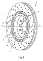
- a disc according to the invention that is destined to be used in a disc brake (not shown) of a vehicle, for example a car.
- the disc 1 has a substantially circular shape that develops around a symmetry axis being indicated with x-x and can be defined a middle plane, the outline thereof being indicated with a dotted line in figure 6 .
- the disc 1 comprises a support bell 2 and a braking band 3, that is coaxial with the support bell 2, being provided with a plurality of connecting elements 4 suitable to connect the braking band 3 to the support bell 2.
- the support bell 2 comprises a central portion 5 destined to be connected, in a conventional manner, to the wheel hub of a vehicle and a peripheral annular portion 6 which is cantilevered from the central portion 5, for example in a direction substantially parallel to x-x axis.
- the braking band 3 is embodied by an annular disc of a preset thickness S and height H, which is coaxially supported by the peripheral annular portion 6 of the support bell 2.
- the braking band 3 is destined to cooperate with the disc brake caliper to exert the braking action on the vehicle.
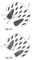
- each of the connecting means 4 is embodied for example by a prismatic projection having a quadrangular section, which is suitable to radially connect the braking band 3 to the support bell 2.
- figure 9.a there is shown how both side faces 40 of the prismatic projection are parallel to the r-r radial axis passing through the center of the projection 4.
- projections having different shapes can be also used.
- the side faces 40 of the projection 4 are not parallel to each other. Each of them defines an angle a with the direction r'-r' parallel to the radial axis r-r passing through the center of the projection.
- the angle ⁇ can vary, according to the particular design requirements, from 0° to 3°. Consequently, the angle 2 ⁇ defined between two opposite faces 40 can vary from 0° and 6.
- the projection 4 has side faces 40 being parallel for the first length thereof being contiguous to the root and convergent in the second end length where a chamfer 42 is formed.
- the projection of figure 9.c is similar to that of figure 9.a , to which the sharp edges at the ends radially near to axis x-x have been chamfered.
- figure 9.c with the chamfered sharp edges besides from a geometry like that of figure 9.a with parallel side faces 40, can also be adopted from a geometry like that in figure 9.b with slightly inclined faces.
- the side faces 40 of the single projection 4 are arranged such as to limit their surface roughness within preset values.
- the side faces 40 of the projections have an average surface roughness R a less than 6.4 ⁇ 10 -6 meters.
- the connecting elements 4, i.e. the projections, are made as one piece with the braking band 3 such as to be integral therewith.
- the projections 4 are joined to the body of the braking band 3 by means of fillets 44. More particularly, the detail of the band section from figure 6.a and the detail of the section in the middle plane of figures 8.a and 8.b should be seen. Upon defining the particular union radius during the design step, one should take into account the type of material employed for manufacturing the braking band 3 in a known manner.
- the projections 4 are housed in corresponding radial housings 8 being obtained in the peripheral annular portion 6 of the support bell 2.
- These radial housings are 8 defined by walls 80 being made as one piece with the bell body 2, such as being integral therewith.
- the radial housings 8 being provided by means of a method that will be described herein below, are perfectly complementary to the side faces 40 of the respective projections 4 or at least some lengths thereof.
- the radial housings 8 at least partially surround the projections 4 such as to restrain the movements thereof in the axial and tangential directions.
- the coupling between the projection 4 and the housing 8 is not an interference coupling, on the contrary it provides a backlash, even though very small.
- the surfaces of the side faces 40 and the walls 80 are intimately coupled to each other without any adhesion to each other. In other words, the surfaces of the side faces 40 and the walls 80 are intimately coupled and disjointed.
- both the walls 80 and the side faces 40 are made such as to allow that, while movements in the axial and tangential directions are prevented because the side faces 40 rest on walls 80, the radial movement of the single projection 4 within the single housing 8 is not prevented by anything.
- the radial movement is not prevented either by macroscopic fittings or micro-telescoping of both materials composing the projection 4 and the walls 80 of housing 8. These micro-telescoping may occur with greater surface roughness of the surfaces.
- the above method for manufacturing the disc according to the invention provides first of all that the braking band 3 be manufactured of a suitable material, for example cast iron.
- the braking band 3 is provided by casting, for example in a sand mould 70.
- the connecting elements 4 are also manufactured, for example the protrusions 4 described above.
- the stock being provided upon the casting step has to be removed in order to bring the braking band to the desired thickness S, and at the same time, to bring the projections 4 to the desired size.
- FIGS 8.a and 8.b show two projections 4 at the end of the casting step and at the end of the step of removing the stock 45, respectively.
- this step there is also defined the geometry of protrusions 4.
- the faces 40 are parallel, or one may provide that they are biased relative to each other according to a small angle, preferably comprised 0° and 6°.
- the desired surface roughness is conferred to the faces of the projections.
- the surface roughness R a will be less than 6.4 ⁇ 10 -6 meters.
- any stock 45 cannot be provided on the projections 4 of the braking band 3, such that the desired geometry is already conferred thereto.
- the braking band can be obtained by means of chill casting instead of sand. It is thus possible to obtain an improved control on the shape of the piece being manufactured by casting.
- the surface finishing step may even be superfluous.
- the projections 4 being manufactured for example by chill casting may already have a suitable surface roughness, without requiring further working to avoid micro-telescoping.
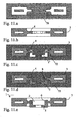
- the method for manufacturing the disc according to the invention provides that the braking band is placed in a mould 72 for casting the support bell 2.
- the mould 72 which is schematically represented in figure 11.c , houses the braking band 3 such as to cause the projections 4 to overhang towards the inside of cavity 2', which is complementary to the shape of the bell 2.
- the molten metal destined to form the bell 2 preferably a light alloy, for example an aluminium alloy is cast in the cavity 2'.
- a housing 8 is manufactured for each projection 4.
- the surfaces of the side faces 40 and the walls 80 thus made are intimately coupled to each other without any adhesion occurring to each other.
- both the walls 80 and the side faces 40 are manufactured such as to allow the radial movement of the single projection 4 within the single housing 8, whereas the movement in the axial and tangential directions are prevented because the side faces 40 rest on the walls 80.
- the radial movement is not prevented either by macroscopic fittings or micro-telescoping of both materials composing the projection 4 and walls 80 of the housing 8. These micro-telescoping may occur with greater surface roughness of the surfaces.
- This protective layer can be made for example of powdered graphite or a resin loaded with powdered graphite.
- the protective layer upon manufacture of the bell 2, due to the temperature of the alloy to which the protective layer is put in contact, the protective layer is carbonized and transformed, in turn, to powdered graphite that is easily removed by shaking or by localized jets of compressed gas. It is thus possible to ensure a backlash slightly greater in the coupling of each projection 4 to the corresponding housing 8.
- the opening step of the moulds provides the disc according to the invention.
- the disc 1 according to the invention when the disc 1 according to the invention is being used, despite the high temperature being reached by the braking band 3, is not subjected to any deformation besides the thermal expansion in its plane. In fact, due to the fact that each projection 4 is enabled to radially slide within its housing 8, the braking band 3 is free to be dilated in its plane independently from the support bell 2.
- the slight backlash allowing the projections 4 to radially slide within the housings 8 can be defined for example during the first operating cycles.
- the poor surface roughness of the side faces 40 and walls 80 allows the projections 4 to slide along the housings 8 since the very beginning.
- the first sliding cycles determine the removal of any micro-relief and hence define the coupling backlash.
- the embodiment of the disc 1 providing a substantial parallelism of the opposite side faces 40 of the projections 4 allows to obtain considerable advantages when the thermal expansion of the braking band 3 is the greatest. In fact, due to the parallelism of the faces 40, to any radial displacement of any projection 4, which is due to the thermal expansion of the braking band 3, there will not follow any increase in the coupling backlash of the projection 4 to the housing 8.
- disc 1 providing a small angle 2 ⁇ between the opposite side faces 40 allows to obtain further advantages whenever the thermal expansion of the projections 4 is non-negligible. In fact, because of the small angle 2 ⁇ , the radial displacement of each projection 4 due to the thermal expansion of the braking band 3 enables each projection 4 to dilate, in turn, without any risk of seizing within the housing 8.
- the embodiment of the disc 1 providing the chamfer 42 of the sharp edges of faces 40 to those ends radially proximate to the axis x-x allows to improve the comfort during the cooling step of the disc 1 at the end of each use session.
- the chamfer 42 during the slight radial displacement of each projection 4 towards the axis x-x, one obtains a clear noise reduction due to the fact that each projection 4 slides within its housing 8.
- the projections 4, being manufactured as one piece with the braking band 3, are capable of withstanding high tangential loads and thus transmitting a considerable braking torque.
- the presence of the fillets 44 allows an optimum distribution of the stress from the projection to the braking band, and vice versa.
- the walls 80 of the housings 8, being manufactured as one piece with the support bell 2 are also capable of withstanding high tangential loads and thus transmitting a considerable braking torque.
- the total braking torque is distributed over a congruous number of projections 4.
- the particular embodiment illustrated in the annexed drawings distributes for example the total torque over 12 projections.
- the number of projections is preferably greater than 6 and still more preferably greater than 10.
- the particular geometry of the projections 4 and housings 8 being illustrated in the annexed drawings also allows to distribute the single braking torque quota proper of each projection over a wide contact surface of the side face 40 of projection 4 to the wall 80 of the housing 8. In this way, it is possible to dramatically reduce the stress peaks on the coupling of the side face 40 with the wall 80.
- the step of surface finishing of the side faces 40 of the projections 4 can be brought to completion by other known methods, such as for example by dipping the workpiece in a vibrating tank containing abrasive elements.
- section of the protrusions 4 can vary from the rectangular one described above, being sufficient to vary also the section of the radial housings in a corresponding manner.
Landscapes
- Engineering & Computer Science (AREA)
- General Engineering & Computer Science (AREA)
- Mechanical Engineering (AREA)
- Braking Arrangements (AREA)
Claims (21)
- Scheibe für eine Scheibenbremse, umfassend eine Trageglocke (2), welche eine Rotationsachse x-x definiert und eine Mehrzahl von radialen Gehäusen (8) aufweist, welche durch Wände (80), welche einteilig mit der Trageglocke (2) sind, definiert sind, ein im Wesentlichen zu der Rotationsachse x-x koaxiales Bremsband (3), und eine Mehrzahl von Verbindungselementen (4), welche Vorsprünge umfassen, die geeignet sind, das Bremsband (3) mit der Trageglocke (2) zu verbinden, wobei:- die Verbindungselemente (4) integral und einteilig mit dem Bremsband (3) hergestellt sind;- die Verbindungselemente (4) Seitenflächen (40) umfassen;
wobei- die Verbindungselemente (4) von dem Bremsband (3) überstehen, um mit den entsprechenden radialen Gehäusen (8) einzugreifen; und- die Verbindungselemente (4) in den radialen Gehäusen (8) aufgenommen sind und wenigstens teilweise von Wänden (80) umgeben sind, welche derart integral und einteilig mit der Trageglocke (2) derart hergestellt sind, dass sie in der radialen Richtung frei sind;- die radialen Gehäuse (8) perfekt komplementär zu den Seitenflächen (40) der entsprechenden Vorsprünge (4) oder wenigstens einigen Längen davon sind;- die beiden Wände (80) und die Seitenflächen (40) derart hergestellt sind, dass sie die radiale Bewegung des einzelnen Vorsprungs (4) innerhalb des einzelnen Gehäuses (8) erlauben,
dadurch gekennzeichnet, dass:- die Oberflächen der Seitenflächen (40) und die Wände (80) innig gekoppelt und unzusammenhängend sind;- die Seitenflächen (40) der Vorsprünge eine durchschnittliche Oberflächenrauhigkeit Ra von weniger als 6,4 * 10-6 Metern aufweisen;- die Verbindungselemente (4) in den radialen Gehäusen (8) derart aufgenommen sind, dass sie in der axialen Richtung und der tangentialen Richtung fixiert sind, und wobei die Bewegung in den axialen und tangentialen Richtungen verhindert wird, da die Seitenflächen (40) an den Wänden (80) ruhen. - Scheibe nach einem der vorhergehenden Ansprüche, wobei die Verbindungselemente (4) ein viereckiges Profil aufweisen.
- Scheibe nach Anspruch 1, wobei die Seitenflächen (40) zueinander parallel sind.
- Scheibe nach Anspruch 1, wobei die Seitenflächen (40) gegeneinander um einen Winkel 2α geneigt sind.
- Scheibe nach Anspruch 4, wobei der Winkel 2α zwischen 0° und 6° liegt.
- Scheibe nach Anspruch 1 und einem der Ansprüche 3 bis 5, wobei die Seitenflächen (40) eine Abschrägung (42) umfassen.
- Scheibe nach einem der vorhergehenden Ansprüche, wobei zwischen dem Bremsband (3) und den Verbindungselementen (4) Leisten (44) angeordnet sind.
- Scheibe nach einem der vorhergehenden Ansprüche, wobei die Kopplung der Verbindungselemente (4) an die Gehäuse (8) eine Kopplung mit Totgang ist.
- Verfahren zum Herstellen einer Scheibe für eine Scheibenbremse, umfassend die Schritte:- Herstellen eines Bremsbands (3), welches eine Rotationsachse x-x definiert;- Anordnen einer Mehrzahl von Verbindungselementen (4), welche Vorsprünge umfassen, welche von dem Bremsband (3) überstehen, an dem Bremsband (3), wobei die Verbindungselemente (4) integral und einteilig mit dem Bremsband (3) hergestellt sind, wobei die Verbindungselemente (4) Seitenflächen (40) umfassen;- Herstellen der Seitenflächen (40) der Vorsprünge (4) derart, dass sie eine durchschnittliche Oberflächenrauhigkeit Ra von weniger als 6,4 * 10-6 Metern aufweisen;- Platzieren des Bremsbands in einer Form (72) zum Gießen einer Trageglocke (2), welche das Bremsband (3) derart aufnimmt, dass die Verbindungselemente (4) dazu gebracht werden, in Richtung der Innenseite des Hohlraums (2'), welcher komplementär zur Form der Glocke (2) ist, überzustehen;- Herstellen einer Trageglocke (2), welche im Wesentlichen koaxial mit der Rotationsachse x-x ist;- Anordnen einer Mehrzahl von radialen Gehäusen (8), welche von Wänden (80) definiert werden, welche integral und einteilig mit der Trageglocke (2) hergestellt sind, an der Trageglocke (2), wobei die Gehäuse geeignet sind, die Verbindungselemente (4) wenigstens teilweise derart aufzunehmen, dass sie in der axialen Richtung und der tangentialen Richtung befestigt sind, und dass sie in der radialen Richtung gleiten können, wobei die radialen Gehäuse (8) perfekt komplementär zu den Seitenflächen (40) der entsprechenden Vorsprünge (4) oder wenigstens einigen Längen davon sind; wobei die Oberflächen der Seitenflächen (40) und der Wände (80) innig gekoppelt und unzusammenhängend sind;- Herstellen beider Seitenwände (80) und der Seitenflächen (40) derart, dass die radiale Bewegung des einzelnen Vorsprungs (4) innerhalb des einzelnen Gehäuses (8) erlaubt wird, wohingegen die Bewegung in den axialen und tangentialen Richtungen verhindert wird, da die Seitenflächen (40) auf den Wänden (80) ruhen.
- Verfahren nach Anspruch 9, wobei der Herstellungsschritt des Bremsbands einen Guss-Schritt umfasst.
- Verfahren nach Anspruch 10, wobei der Guss-Schritt einen Sandguss-Schritt umfasst.
- Verfahren nach Anspruch 10, wobei der Guss-Schritt einen Kokillenguss-Schritt umfasst.
- Verfahren nach einem der Ansprüche 9 bis 12, wobei dem Herstellungsschritt des Bremsbands (3) ein Schritt des Entfernens einer Gussform (35, 45) nachfolgt.
- Verfahren nach einem der Ansprüche 9 bis 13, wobei der Herstellungsschritt des Bremsbands (3) einen Schritt des Anordnens von Abschrägungen (42) an den Verbindungselementen (4) umfasst.
- Verfahren nach einem der Ansprüche 9 bis 14, wobei der Herstellungsschritt des Bremsbands (3) einen Schritt der Endbearbeitung der Oberfläche der Verbindungselemente (4) umfasst.
- Verfahren nach einem der Ansprüche 9 bis 15, wobei dem Schritt der Herstellung des Bremsbands (3) ein Schritt eines Anordnens einer Oberflächen-Schutzschicht an den Verbindungselementen (4) folgt.
- Verfahren nach Anspruch 16, wobei der Schritt des Anordnens einer Oberflächen-Schutzschicht an den Verbindungselementen (4) einen Schritt eines Anordnens einer Schutzschicht, welche Graphit enthält, umfasst.
- Verfahren nach einem der Ansprüche 9 bis 17, wobei der Schritt der Herstellung der Trageglocke (2) dem Schritt der Herstellung des Bremsbands (3) folgt.
- Verfahren nach Anspruch 15, wobei der Schritt der Herstellung der Trageglocke (2) dem Schritt der Endbearbeitung der Oberfläche der Verbindungselemente (4) folgt.
- Verfahren nach einem der Ansprüche 9 bis 19, wobei der Schritt des Herstellens der Trageglocke (2) einen Guss-Schritt umfasst.
- Verfahren nach Anspruch 16, wobei dem Schritt des Herstellens der Trageglocke (2) ein Schritt eines Entfernens der Oberflächen-Schutzschicht folgt.
Priority Applications (2)
| Application Number | Priority Date | Filing Date | Title |
|---|---|---|---|
| EP10185290A EP2275702B1 (de) | 2004-10-26 | 2004-10-26 | Scheibe für eine Scheibenbremse |
| PL10185290T PL2275702T3 (pl) | 2004-10-26 | 2004-10-26 | Tarcza do hamulca tarczowego |
Applications Claiming Priority (1)
| Application Number | Priority Date | Filing Date | Title |
|---|---|---|---|
| PCT/IT2004/000590 WO2006046258A1 (en) | 2004-10-26 | 2004-10-26 | Disc for a disc brake |
Related Child Applications (2)
| Application Number | Title | Priority Date | Filing Date |
|---|---|---|---|
| EP10185290A Division-Into EP2275702B1 (de) | 2004-10-26 | 2004-10-26 | Scheibe für eine Scheibenbremse |
| EP10185290.3 Division-Into | 2010-10-01 |
Publications (4)
| Publication Number | Publication Date |
|---|---|
| EP1805430A1 EP1805430A1 (de) | 2007-07-11 |
| EP1805430B1 EP1805430B1 (de) | 2013-02-13 |
| EP1805430B2 true EP1805430B2 (de) | 2015-09-16 |
| EP1805430B8 EP1805430B8 (de) | 2015-12-30 |
Family
ID=34959427
Family Applications (2)
| Application Number | Title | Priority Date | Filing Date |
|---|---|---|---|
| EP10185290A Expired - Lifetime EP2275702B1 (de) | 2004-10-26 | 2004-10-26 | Scheibe für eine Scheibenbremse |
| EP04791924.6A Expired - Lifetime EP1805430B8 (de) | 2004-10-26 | 2004-10-26 | Scheibenbremse |
Family Applications Before (1)
| Application Number | Title | Priority Date | Filing Date |
|---|---|---|---|
| EP10185290A Expired - Lifetime EP2275702B1 (de) | 2004-10-26 | 2004-10-26 | Scheibe für eine Scheibenbremse |
Country Status (6)
| Country | Link |
|---|---|
| US (1) | US20070246314A1 (de) |
| EP (2) | EP2275702B1 (de) |
| JP (1) | JP4897693B2 (de) |
| CN (1) | CN101052820B (de) |
| PL (1) | PL2275702T3 (de) |
| WO (1) | WO2006046258A1 (de) |
Families Citing this family (39)
| Publication number | Priority date | Publication date | Assignee | Title |
|---|---|---|---|---|
| DE102006043945A1 (de) | 2006-09-14 | 2008-03-27 | Schwäbische Hüttenwerke Automotive GmbH & Co. KG | Belüftete Bremsscheibe |
| DE102007001567B4 (de) | 2007-01-10 | 2009-07-02 | Fritz Winter Eisengiesserei Gmbh & Co. Kg | Bremsscheibe für eine Scheibenbremse |
| DE102007013512A1 (de) * | 2007-03-21 | 2008-09-25 | Audi Ag | Bremsscheibe für eine Scheibenbremse eines Fahrzeugs sowie Verfahren zur Herstellung einer solchen Bremsscheibe |
| ITBS20070067A1 (it) | 2007-05-03 | 2008-11-04 | Freni Brembo Spa | Disco freno ventilato |
| ITMI20070881A1 (it) * | 2007-05-03 | 2008-11-04 | Freni Brembo Spa | Disco freno ventilato |
| CN102239344B (zh) * | 2008-05-08 | 2014-11-12 | 瑞锡尼弗莱诺斯可变资本股份公司 | 复合制动盘 |
| DE102008042168A1 (de) * | 2008-09-17 | 2010-03-18 | Robert Bosch Gmbh | Bremsscheibe |
| DE102008042173A1 (de) * | 2008-09-17 | 2010-03-18 | Robert Bosch Gmbh | Bremsscheibe |
| DE102008042165A1 (de) * | 2008-09-17 | 2010-03-25 | Robert Bosch Gmbh | Bremsscheibe |
| CA2767252A1 (en) * | 2009-07-06 | 2011-01-13 | Knorr-Bremse Systeme Fuer Nutzfahrzeuge Gmbh | Brake disc implemented as a casting |
| IT1395120B1 (it) * | 2009-07-29 | 2012-09-05 | Freni Brembo Spa | Fascia di frenatura e disco per freno a disco |
| DE102009049315B4 (de) | 2009-10-14 | 2011-10-20 | Volkswagen Ag | Vorrichtung zum Herstellen eines Verbundgussteiles |
| US8646586B2 (en) * | 2010-06-15 | 2014-02-11 | John Catrinta | Torque-limiting clutch brake |
| DE102010024389A1 (de) * | 2010-06-19 | 2011-12-22 | Audi Ag | Verbindungseinrichtung zwischen Reibring und Topf einer Bremsscheibe |
| KR101223448B1 (ko) * | 2010-09-28 | 2013-01-17 | 현대자동차주식회사 | 어댑터 분리형 디스크로터의 구조 |
| IT1403905B1 (it) | 2011-01-26 | 2013-11-08 | Freni Brembo Spa | Disco per freni a disco |
| DE102011101126B3 (de) | 2011-05-11 | 2012-10-18 | Audi Ag | Verfahren zum Herstellen einer Verbundguss-Bremsscheibe |
| KR101294165B1 (ko) | 2011-08-10 | 2013-08-08 | 현대자동차주식회사 | 이종재질의 브레이크 디스크 및 그 제조방법 |
| DE102011116601A1 (de) * | 2011-10-21 | 2013-04-25 | Audi Ag | Innenbelüftete Bremsscheibe |
| DE102012010729B4 (de) | 2012-05-31 | 2017-05-24 | Audi Ag | Verfahren zur Herstellung einer Bremsscheibe und derart hergestellte Bremsscheibe |
| EP2716930A1 (de) | 2012-10-03 | 2014-04-09 | Georg Fischer Kokillenguss GmbH | Hybridbremse |
| CN102966689B (zh) * | 2012-12-27 | 2016-01-20 | 郑州精益达汽车零部件有限公司 | 汽车用制动盘 |
| DE102013002300B3 (de) | 2013-02-08 | 2014-07-17 | Audi Ag | Bremsscheibe für eine Scheibenbremse eines Kraftfahrzeugs |
| JP5778205B2 (ja) * | 2013-04-10 | 2015-09-16 | 三木プーリ株式会社 | 無励磁作動形ブレーキ用ロータ |
| KR20150061665A (ko) * | 2013-11-18 | 2015-06-05 | 현대자동차주식회사 | 이종재질의 브레이크 디스크 및 그 제조방법 |
| ITMI20132137A1 (it) | 2013-12-19 | 2015-06-20 | Freni Brembo Spa | Disco freno ventilato |
| KR101551969B1 (ko) | 2013-12-31 | 2015-09-09 | 현대자동차주식회사 | 이종재질의 브레이크 디스크 및 이의 제조방법 |
| CN104132084A (zh) * | 2014-06-27 | 2014-11-05 | 陈晓曦 | 一种汽车刹车盘 |
| EP2980436B1 (de) * | 2014-07-28 | 2018-10-10 | Brembo SGL Carbon Ceramic Brakes S.p.A. | Scheibe für Scheibenbremsen und Verfahren zur Herstellung davon |
| KR101856288B1 (ko) * | 2015-06-16 | 2018-05-10 | 현대자동차주식회사 | 드럼 인 햇 브레이크 디스크 및 그 제조방법 |
| DE102016122321B4 (de) | 2016-11-21 | 2019-04-25 | Shw Automotive Gmbh | Bremsscheibe |
| US10612612B2 (en) * | 2016-11-22 | 2020-04-07 | Hyundai Motor Company | Solid type brake disc and manufacturing method of the same |
| AU2019356796A1 (en) * | 2018-10-09 | 2021-03-18 | Disc Brakes Australia Pty. Limited | Disc brakes rotor and method of manufacture |
| DE102018218093A1 (de) | 2018-10-23 | 2020-04-23 | Audi Ag | Innenbelüftete Bremsscheibe |
| IT201800020128A1 (it) * | 2018-12-18 | 2020-06-18 | Freni Brembo Spa | Fascia di frenatura di un disco per freno a disco di tipo ventilato |
| ES2883174T3 (es) | 2019-02-08 | 2021-12-07 | SHW Brake Systems GmbH | Disco de freno |
| IT201900025222A1 (it) | 2019-12-23 | 2021-06-23 | Freni Brembo Spa | Disco di freno a disco, freno a disco e metodo di produzione |
| DE102021118571A1 (de) * | 2021-07-19 | 2023-01-19 | Elringklinger Ag | Bremssystem |
| DE102023116880B4 (de) | 2023-06-27 | 2025-04-03 | SHW Brake Systems GmbH | Bremsscheibe |
Citations (2)
| Publication number | Priority date | Publication date | Assignee | Title |
|---|---|---|---|---|
| DE3920418A1 (de) † | 1989-06-22 | 1991-01-03 | Schwaebische Huettenwerke Gmbh | Bremsscheibe fuer scheibenbremsen |
| WO2002046638A1 (de) † | 2000-12-05 | 2002-06-13 | Fritz Winter Eisengiesserei Gmbh & Co. Kg | Verfahren zum herstellen einer bremsscheibe und kernformwerkzeug |
Family Cites Families (15)
| Publication number | Priority date | Publication date | Assignee | Title |
|---|---|---|---|---|
| US2412432A (en) * | 1945-04-26 | 1946-12-10 | American Steel Foundries | Brake rotor |
| DE2115299C3 (de) * | 1971-03-30 | 1979-11-08 | Guenter 7031 Aidlingen Funke | Verfahren zur Herstellung von VerbundguBbremsscheiben und Vorrichtung zur Durchführung des Verfahrens |
| EP0077137B1 (de) * | 1981-10-01 | 1987-04-22 | Automotive Products Public Limited Company | Verfahren zur Herstellung einer Bremsscheibe |
| US5161652A (en) * | 1988-10-18 | 1992-11-10 | Honda Giken Kogyo Kabushiki Kaisha | Ventilated disk brake rotor |
| DE4003732A1 (de) * | 1990-02-08 | 1991-08-14 | Teves Gmbh Alfred | Bremsscheibe fuer scheibenbremsen von fahrzeugen, insbesondere kettenfahrzeugen |
| US5823303A (en) * | 1993-01-28 | 1998-10-20 | Schwaebische Huettenwerke Gmbh | Brake disc |
| IT230648Y1 (it) * | 1993-10-18 | 1999-06-09 | Brembo Spa | Disco di un freno a disco per veicoli in generale e per vetture ad elevate prestazioni in particolare |
| DE4445226A1 (de) * | 1994-12-17 | 1996-06-20 | Porsche Ag | Bremsscheiben für Scheibenbremsen |
| IT1288795B1 (it) * | 1996-10-31 | 1998-09-24 | Skf Ind Spa | Gruppo cuscinetto per mozzo ruota di veicolo adatto al collegamento con l'organo frenante per formatura a freddo. |
| EP0933550A1 (de) * | 1998-02-02 | 1999-08-04 | ALUMINIUM RHEINFELDEN GmbH | Bremsscheibe |
| DE19929390B4 (de) * | 1999-06-28 | 2004-05-06 | Otto Sauer Achsenfabrik Keilberg | Bremsscheibenanordnung |
| EP1092889B1 (de) * | 1999-10-14 | 2003-04-09 | Freni Brembo S.p.A. | Scheibe für eine Scheibenbremse |
| EP1122456B1 (de) * | 2000-03-09 | 2001-08-16 | Freni Brembo S.p.A. | Belüftete Scheibe für Scheibenbremse |
| EP1229265A1 (de) * | 2001-02-01 | 2002-08-07 | Visteon Global Technologies, Inc. | Bremsscheibe |
| US6523651B2 (en) * | 2000-09-14 | 2003-02-25 | Visteon Global Technologies, Inc. | Brake disc with hat section having ribs that support a friction ring without bonding |
-
2004
- 2004-10-26 CN CN2004800443042A patent/CN101052820B/zh not_active Expired - Lifetime
- 2004-10-26 PL PL10185290T patent/PL2275702T3/pl unknown
- 2004-10-26 JP JP2007538616A patent/JP4897693B2/ja not_active Expired - Lifetime
- 2004-10-26 EP EP10185290A patent/EP2275702B1/de not_active Expired - Lifetime
- 2004-10-26 WO PCT/IT2004/000590 patent/WO2006046258A1/en not_active Ceased
- 2004-10-26 US US11/577,289 patent/US20070246314A1/en not_active Abandoned
- 2004-10-26 EP EP04791924.6A patent/EP1805430B8/de not_active Expired - Lifetime
Patent Citations (2)
| Publication number | Priority date | Publication date | Assignee | Title |
|---|---|---|---|---|
| DE3920418A1 (de) † | 1989-06-22 | 1991-01-03 | Schwaebische Huettenwerke Gmbh | Bremsscheibe fuer scheibenbremsen |
| WO2002046638A1 (de) † | 2000-12-05 | 2002-06-13 | Fritz Winter Eisengiesserei Gmbh & Co. Kg | Verfahren zum herstellen einer bremsscheibe und kernformwerkzeug |
Also Published As
| Publication number | Publication date |
|---|---|
| EP1805430A1 (de) | 2007-07-11 |
| EP2275702A3 (de) | 2011-01-26 |
| CN101052820B (zh) | 2010-05-26 |
| WO2006046258A8 (en) | 2007-06-07 |
| PL2275702T3 (pl) | 2013-06-28 |
| WO2006046258A1 (en) | 2006-05-04 |
| JP2008518175A (ja) | 2008-05-29 |
| EP1805430B1 (de) | 2013-02-13 |
| CN101052820A (zh) | 2007-10-10 |
| US20070246314A1 (en) | 2007-10-25 |
| EP2275702B1 (de) | 2012-11-28 |
| EP1805430B8 (de) | 2015-12-30 |
| EP2275702A2 (de) | 2011-01-19 |
| JP4897693B2 (ja) | 2012-03-14 |
Similar Documents
| Publication | Publication Date | Title |
|---|---|---|
| EP1805430B2 (de) | Scheibenbremse | |
| US10203008B2 (en) | Disc for a disc brake | |
| CN101743411B (zh) | 通风制动盘 | |
| EP2668414B1 (de) | Scheibe für scheibenbremsen | |
| US8118079B2 (en) | Casting noise-damped, vented brake rotors with embedded inserts | |
| US9360066B2 (en) | Method for producing a brake carrier for a disc brake and brake carrier for a disc brake | |
| CN1318137A (zh) | 生产由带有金属毂的陶瓷部件组成的制动片的方法 | |
| JP6916954B2 (ja) | ブレーキディスクおよびブレーキディスクの製造方法 | |
| MX2007010737A (es) | Disco de freno, en particular para un vehiculo. | |
| EP1433973A1 (de) | Bremsscheibe | |
| EP4081721B1 (de) | Scheibenbremsscheibe, scheibenbremse und herstellungsverfahren | |
| US20080010806A1 (en) | Method and tools for the production of a braking band for a brake disk | |
| EP1352179A1 (de) | Bremsband und scheibe für eine scheibenbremse | |
| JPH0238815B2 (de) | ||
| EP1327085B1 (de) | Bremsscheibe | |
| JP7633231B2 (ja) | ベンチレーテッドタイプのディスクブレーキ用ブレーキバンド | |
| JP7541506B2 (ja) | 車両用ディスクブレーキのキャリパボディ | |
| JP2004520543A (ja) | ディスクブレーキのためのオートバイ用軽量ディスク並びに各製造方法 | |
| WO2003089802A1 (en) | Bell for braking disc and disc for a disc brake | |
| US1122583A (en) | Segmental brake-shoe. | |
| JPH0449392Y2 (de) | ||
| JPH10277703A (ja) | ディスクロータ用鋳型 | |
| JP2010270802A (ja) | ブレーキディスク | |
| JPS6298037A (ja) | デイスクブレ−キ用デイスクロ−タ | |
| CS197648B1 (cs) | Brzdový kotouč |
Legal Events
| Date | Code | Title | Description |
|---|---|---|---|
| PUAI | Public reference made under article 153(3) epc to a published international application that has entered the european phase |
Free format text: ORIGINAL CODE: 0009012 |
|
| 17P | Request for examination filed |
Effective date: 20070305 |
|
| AK | Designated contracting states |
Kind code of ref document: A1 Designated state(s): AT BE BG CH CY CZ DE DK EE ES FI FR GB GR HU IE IT LI LU MC NL PL PT RO SE SI SK TR |
|
| DAX | Request for extension of the european patent (deleted) | ||
| 17Q | First examination report despatched |
Effective date: 20081205 |
|
| R17C | First examination report despatched (corrected) |
Effective date: 20081205 |
|
| GRAP | Despatch of communication of intention to grant a patent |
Free format text: ORIGINAL CODE: EPIDOSNIGR1 |
|
| GRAS | Grant fee paid |
Free format text: ORIGINAL CODE: EPIDOSNIGR3 |
|
| GRAA | (expected) grant |
Free format text: ORIGINAL CODE: 0009210 |
|
| AK | Designated contracting states |
Kind code of ref document: B1 Designated state(s): AT BE BG CH CY CZ DE DK EE ES FI FR GB GR HU IE IT LI LU MC NL PL PT RO SE SI SK TR |
|
| REG | Reference to a national code |
Ref country code: GB Ref legal event code: FG4D |
|
| REG | Reference to a national code |
Ref country code: AT Ref legal event code: REF Ref document number: 596662 Country of ref document: AT Kind code of ref document: T Effective date: 20130215 |
|
| REG | Reference to a national code |
Ref country code: IE Ref legal event code: FG4D |
|
| REG | Reference to a national code |
Ref country code: DE Ref legal event code: R096 Ref document number: 602004040986 Country of ref document: DE Effective date: 20130411 |
|
| REG | Reference to a national code |
Ref country code: AT Ref legal event code: MK05 Ref document number: 596662 Country of ref document: AT Kind code of ref document: T Effective date: 20130213 |
|
| REG | Reference to a national code |
Ref country code: NL Ref legal event code: VDEP Effective date: 20130213 |
|
| PG25 | Lapsed in a contracting state [announced via postgrant information from national office to epo] |
Ref country code: SE Free format text: LAPSE BECAUSE OF FAILURE TO SUBMIT A TRANSLATION OF THE DESCRIPTION OR TO PAY THE FEE WITHIN THE PRESCRIBED TIME-LIMIT Effective date: 20130213 Ref country code: AT Free format text: LAPSE BECAUSE OF FAILURE TO SUBMIT A TRANSLATION OF THE DESCRIPTION OR TO PAY THE FEE WITHIN THE PRESCRIBED TIME-LIMIT Effective date: 20130213 Ref country code: ES Free format text: LAPSE BECAUSE OF FAILURE TO SUBMIT A TRANSLATION OF THE DESCRIPTION OR TO PAY THE FEE WITHIN THE PRESCRIBED TIME-LIMIT Effective date: 20130524 Ref country code: BG Free format text: LAPSE BECAUSE OF FAILURE TO SUBMIT A TRANSLATION OF THE DESCRIPTION OR TO PAY THE FEE WITHIN THE PRESCRIBED TIME-LIMIT Effective date: 20130513 |
|
| PG25 | Lapsed in a contracting state [announced via postgrant information from national office to epo] |
Ref country code: SI Free format text: LAPSE BECAUSE OF FAILURE TO SUBMIT A TRANSLATION OF THE DESCRIPTION OR TO PAY THE FEE WITHIN THE PRESCRIBED TIME-LIMIT Effective date: 20130213 Ref country code: GR Free format text: LAPSE BECAUSE OF FAILURE TO SUBMIT A TRANSLATION OF THE DESCRIPTION OR TO PAY THE FEE WITHIN THE PRESCRIBED TIME-LIMIT Effective date: 20130514 Ref country code: PL Free format text: LAPSE BECAUSE OF FAILURE TO SUBMIT A TRANSLATION OF THE DESCRIPTION OR TO PAY THE FEE WITHIN THE PRESCRIBED TIME-LIMIT Effective date: 20130213 Ref country code: FI Free format text: LAPSE BECAUSE OF FAILURE TO SUBMIT A TRANSLATION OF THE DESCRIPTION OR TO PAY THE FEE WITHIN THE PRESCRIBED TIME-LIMIT Effective date: 20130213 Ref country code: BE Free format text: LAPSE BECAUSE OF FAILURE TO SUBMIT A TRANSLATION OF THE DESCRIPTION OR TO PAY THE FEE WITHIN THE PRESCRIBED TIME-LIMIT Effective date: 20130213 Ref country code: PT Free format text: LAPSE BECAUSE OF FAILURE TO SUBMIT A TRANSLATION OF THE DESCRIPTION OR TO PAY THE FEE WITHIN THE PRESCRIBED TIME-LIMIT Effective date: 20130613 |
|
| PG25 | Lapsed in a contracting state [announced via postgrant information from national office to epo] |
Ref country code: EE Free format text: LAPSE BECAUSE OF FAILURE TO SUBMIT A TRANSLATION OF THE DESCRIPTION OR TO PAY THE FEE WITHIN THE PRESCRIBED TIME-LIMIT Effective date: 20130213 Ref country code: NL Free format text: LAPSE BECAUSE OF FAILURE TO SUBMIT A TRANSLATION OF THE DESCRIPTION OR TO PAY THE FEE WITHIN THE PRESCRIBED TIME-LIMIT Effective date: 20130213 Ref country code: SK Free format text: LAPSE BECAUSE OF FAILURE TO SUBMIT A TRANSLATION OF THE DESCRIPTION OR TO PAY THE FEE WITHIN THE PRESCRIBED TIME-LIMIT Effective date: 20130213 Ref country code: DK Free format text: LAPSE BECAUSE OF FAILURE TO SUBMIT A TRANSLATION OF THE DESCRIPTION OR TO PAY THE FEE WITHIN THE PRESCRIBED TIME-LIMIT Effective date: 20130213 Ref country code: CZ Free format text: LAPSE BECAUSE OF FAILURE TO SUBMIT A TRANSLATION OF THE DESCRIPTION OR TO PAY THE FEE WITHIN THE PRESCRIBED TIME-LIMIT Effective date: 20130213 Ref country code: RO Free format text: LAPSE BECAUSE OF FAILURE TO SUBMIT A TRANSLATION OF THE DESCRIPTION OR TO PAY THE FEE WITHIN THE PRESCRIBED TIME-LIMIT Effective date: 20130213 |
|
| PG25 | Lapsed in a contracting state [announced via postgrant information from national office to epo] |
Ref country code: CY Free format text: LAPSE BECAUSE OF FAILURE TO SUBMIT A TRANSLATION OF THE DESCRIPTION OR TO PAY THE FEE WITHIN THE PRESCRIBED TIME-LIMIT Effective date: 20130213 |
|
| PLBI | Opposition filed |
Free format text: ORIGINAL CODE: 0009260 |
|
| PLAX | Notice of opposition and request to file observation + time limit sent |
Free format text: ORIGINAL CODE: EPIDOSNOBS2 |
|
| 26 | Opposition filed |
Opponent name: FRITZ WINTER EISENGIESSEREI GMBH & CO. KG Effective date: 20131113 |
|
| REG | Reference to a national code |
Ref country code: DE Ref legal event code: R026 Ref document number: 602004040986 Country of ref document: DE Effective date: 20131113 |
|
| PLBB | Reply of patent proprietor to notice(s) of opposition received |
Free format text: ORIGINAL CODE: EPIDOSNOBS3 |
|
| PG25 | Lapsed in a contracting state [announced via postgrant information from national office to epo] |
Ref country code: MC Free format text: LAPSE BECAUSE OF FAILURE TO SUBMIT A TRANSLATION OF THE DESCRIPTION OR TO PAY THE FEE WITHIN THE PRESCRIBED TIME-LIMIT Effective date: 20130213 |
|
| REG | Reference to a national code |
Ref country code: CH Ref legal event code: PL |
|
| GBPC | Gb: european patent ceased through non-payment of renewal fee |
Effective date: 20131026 |
|
| REG | Reference to a national code |
Ref country code: IE Ref legal event code: MM4A |
|
| PG25 | Lapsed in a contracting state [announced via postgrant information from national office to epo] |
Ref country code: GB Free format text: LAPSE BECAUSE OF NON-PAYMENT OF DUE FEES Effective date: 20131026 Ref country code: LI Free format text: LAPSE BECAUSE OF NON-PAYMENT OF DUE FEES Effective date: 20131031 Ref country code: CH Free format text: LAPSE BECAUSE OF NON-PAYMENT OF DUE FEES Effective date: 20131031 |
|
| REG | Reference to a national code |
Ref country code: FR Ref legal event code: ST Effective date: 20140630 |
|
| PG25 | Lapsed in a contracting state [announced via postgrant information from national office to epo] |
Ref country code: FR Free format text: LAPSE BECAUSE OF NON-PAYMENT OF DUE FEES Effective date: 20131031 |
|
| PG25 | Lapsed in a contracting state [announced via postgrant information from national office to epo] |
Ref country code: IE Free format text: LAPSE BECAUSE OF NON-PAYMENT OF DUE FEES Effective date: 20131026 |
|
| PG25 | Lapsed in a contracting state [announced via postgrant information from national office to epo] |
Ref country code: TR Free format text: LAPSE BECAUSE OF FAILURE TO SUBMIT A TRANSLATION OF THE DESCRIPTION OR TO PAY THE FEE WITHIN THE PRESCRIBED TIME-LIMIT Effective date: 20130213 |
|
| PG25 | Lapsed in a contracting state [announced via postgrant information from national office to epo] |
Ref country code: HU Free format text: LAPSE BECAUSE OF FAILURE TO SUBMIT A TRANSLATION OF THE DESCRIPTION OR TO PAY THE FEE WITHIN THE PRESCRIBED TIME-LIMIT; INVALID AB INITIO Effective date: 20041026 Ref country code: LU Free format text: LAPSE BECAUSE OF NON-PAYMENT OF DUE FEES Effective date: 20131026 |
|
| PUAH | Patent maintained in amended form |
Free format text: ORIGINAL CODE: 0009272 |
|
| STAA | Information on the status of an ep patent application or granted ep patent |
Free format text: STATUS: PATENT MAINTAINED AS AMENDED |
|
| 27A | Patent maintained in amended form |
Effective date: 20150916 |
|
| AK | Designated contracting states |
Kind code of ref document: B2 Designated state(s): AT BE BG CH CY CZ DE DK EE ES FI FR GB GR HU IE IT LI LU MC NL PL PT RO SE SI SK TR |
|
| REG | Reference to a national code |
Ref country code: DE Ref legal event code: R102 Ref document number: 602004040986 Country of ref document: DE |
|
| REG | Reference to a national code |
Ref country code: DE Ref legal event code: R081 Ref document number: 602004040986 Country of ref document: DE Owner name: BREMBO S.P.A., CURNO, IT Free format text: FORMER OWNER: FRENI BREMBO S.P.A., CURNO, BERGAMO, IT |
|
| P01 | Opt-out of the competence of the unified patent court (upc) registered |
Effective date: 20230530 |
|
| PGFP | Annual fee paid to national office [announced via postgrant information from national office to epo] |
Ref country code: IT Payment date: 20230807 Year of fee payment: 20 |
|
| PGFP | Annual fee paid to national office [announced via postgrant information from national office to epo] |
Ref country code: DE Payment date: 20231020 Year of fee payment: 20 |
|
| REG | Reference to a national code |
Ref country code: DE Ref legal event code: R071 Ref document number: 602004040986 Country of ref document: DE |